


MF68-00258A
DIGITAL SATELLITE RECEIVER
DSR 9500AX / 9500AY / 9500AZ
DSR 9510X / 9510Y / 9510Z
Instructions foruse
REV. 1.4
DIGITAL SATELLITE RECEIVER

SAFETY INSTRUCTIONS
This STB has been manufactured to satisfy international safety standards. Please read the following recommended safety precautions carefully.
MAINS SUPPLY: AC 100-240V ~, 50/60Hz
OVERLOADING: Do not overload wall outlets, extension cords or adapters as this can result in fire or electrical shock.
LIQUIDS: Keep liquids away from the STB.
CLEANING: Before cleaning, disconnect the STB from the wall socket. Use a cloth lightly dampened with water(no solvents) to clean the exterior.
VENTILATION: Do not block the STB ventilation holes. Ensure that free airflow is maintained around the STB. Never store the STB where it is exposed to direct sunlight or near heating euipment e.g. a radiator.
Never stack other electronic equipment on top of the STB. Place the STB at least 30mm from the wall.
ATTACHMENTS: Do not use any attachment that is not recommended by the manufacturer; it may cause a hazard or damage the equipment.
CONNECTION TO THE SATELLITE DISH LNB:
The LNB connector cable has voltage in its center core. It is therefore recommended that the STB be disconnected from the mains power before connecting or disconnecting this cable. FAILURE TO DO SO COULD DAMAGE THE LNB.
SERVICING: Do not attempt to service this product yourself. Any attempt to do so will make the warranty invalid. Refer all servicing to a qualified service agent.
LIGHTNING: If the STB is installed in an area subject to intense lightning activity, protection devices for the STB mains connector and modem telephone line are essential.
The individual manufacturer’s instruction for safeguarding other equipment, such as TV set, Hi-Fi, etc., connected to the STB must also be followed during lightning storms.
GROUNDING: The ground of the LNB cable must be directly connected to the system ground for the satellite dish.
The grounding system must comply with local regulations
Note : Dispose the used batteries at designated place for environment protection
GB-1

CONTENT
Safety Instructions . . . . . . . . . . . . . . . . . . . . . . . . . . . . . . . . . . . . . 1 General Features . . . . . . . . . . . . . . . . . . . . . . . . . . . . . . . . . . . . . . . 3 Connecting Your STB . . . . . . . . . . . . . . . . . . . . . . . . . . . . . . . . . . . 4 Description . . . . . . . . . . . . . . . . . . . . . . . . . . . . . . . . . . . . . . . . . . . 6 Front Panel . . . . . . . . . . . . . . . . . . . . . . . . . . . . . . . . . . . . . . . . . . . 6 Rear Panel . . . . . . . . . . . . . . . . . . . . . . . . . . . . . . . . . . . . . . . . . . . 7 Remote Control Unit . . . . . . . . . . . . . . . . . . . . . . . . . . . . . . . . . . . . 8 Basic Functions . . . . . . . . . . . . . . . . . . . . . . . . . . . . . . . . . . . . . . . . 10 Operating The Receiver . . . . . . . . . . . . . . . . . . . . . . . . . . . . . . . . . 15 Main Menu . . . . . . . . . . . . . . . . . . . . . . . . . . . . . . . . . . . . . . . . . . . . 15 1. Installation . . . . . . . . . . . . . . . . . . . . . . . . . . . . . . . . . . . . . . . . 15
1.1 LNB Setting . . . . . . . . . . . . . . . . . . . . . . . . . . . . . . . . . . . . 16 1.2 Positioner Setting. . . . . . . . . . . . . . . . . . . . . . . . . . . . . . . . 16 1.2.1 User Mode . . . . . . . . . . . . . . . . . . . . . . . . . . . . . . . . . . . 17 1.2.2 Installer Mode . . . . . . . . . . . . . . . . . . . . . . . . . . . . . . . . . 18 1.3 Solarsat Setting . . . . . . . . . . . . . . . . . . . . . . . . . . . . . . . . . 18 1.4 Auto Scanning . . . . . . . . . . . . . . . . . . . . . . . . . . . . . . . . . . 18 1.5 Manual Scanning . . . . . . . . . . . . . . . . . . . . . . . . . . . . . . . . 19 1.6 SMATV Scanning . . . . . . . . . . . . . . . . . . . . . . . . . . . . . . . . 20 1.7 Reset to Factory Defaults . . . . . . . . . . . . . . . . . . . . . . . . . . 20
2. Channel Organising . . . . . . . . . . . . . . . . . . . . . . . . . . . . . . . . . 21 2.1 Delete Satellite . . . . . . . . . . . . . . . . . . . . . . . . . . . . . . . . . . 21 2.2 Delete Transponder . . . . . . . . . . . . . . . . . . . . . . . . . . . . . . 21 2.3 Delete Channel . . . . . . . . . . . . . . . . . . . . . . . . . . . . . . . . . 22 2.4 Delete All Channel . . . . . . . . . . . . . . . . . . . . . . . . . . . . . . . 22 2.5 Delete Scrambled Channels . . . . . . . . . . . . . . . . . . . . . . . . 22 2.6 Favorite Channel . . . . . . . . . . . . . . . . . . . . . . . . . . . . . . . . 22 2.7 Move & Edit Channel . . . . . . . . . . . . . . . . . . . . . . . . . . . . . 23
3. Parental Lock . . . . . . . . . . . . . . . . . . . . . . . . . . . . . . . . . . . . . . 24 3.1 Set Channel Lock. . . . . . . . . . . . . . . . . . . . . . . . . . . . . . . . 24 3.2 Change PIN Code . . . . . . . . . . . . . . . . . . . . . . . . . . . . . . . 25
4. System Setup . . . . . . . . . . . . . . . . . . . . . . . . . . . . . . . . . . . . . . 26 4.1 Language Selection . . . . . . . . . . . . . . . . . . . . . . . . . . . . . . 26 4.2 OSD Setting. . . . . . . . . . . . . . . . . . . . . . . . . . . . . . . . . . . . 26 4.3 Media Settings . . . . . . . . . . . . . . . . . . . . . . . . . . . . . . . . . . 27 4.4 Modem Setting . . . . . . . . . . . . . . . . . . . . . . . . . . . . . . . . . 27 4.5 Time &Timer Setting . . . . . . . . . . . . . . . . . . . . . . . . . . . . . . 27 4.6 System Information . . . . . . . . . . . . . . . . . . . . . . . . . . . . . . 28 4.7 Software Upgrade . . . . . . . . . . . . . . . . . . . . . . . . . . . . . . . 28 4.8 Copy Channel Data . . . . . . . . . . . . . . . . . . . . . . . . . . . . . . 28
5. Common Interface . . . . . . . . . . . . . . . . . . . . . . . . . . . . . . . . . . 29 6. Embedded CAS. . . . . . . . . . . . . . . . . . . . . . . . . . . . . . . . . . . . . 29 Troubleshooting. . . . . . . . . . . . . . . . . . . . . . . . . . . . . . . . . . . . . . . . 30 Disposal . . . . . . . . . . . . . . . . . . . . . . . . . . . . . . . . . . . . . . . . . . . . . . 30 Technical Specifications . . . . . . . . . . . . . . . . . . . . . . . . . . . . . . . . . 31
GB-2
D I G I T A L S A T E L

GENERAL FEATURES
1. USER SECTION
 4000 PROGRAMMABLE CHANNELS
 SOFTWARE DOWNLOAD VIA SATELLITE & PC(Secured)
 ADVANCED ELECTRONIC PROGRAM GUIDE
 MULTI LANGUAGE SUPPORTED FOR OSD
 SUBTITLE & TELETEXT(OSD & VBI)SUPPORTED WITH MULTI LANGUAGE
 DiSEqC 1.2 SUPPORTED
 FULL FUNCTION INFRARED REMOTE CONTROL UNIT
 7 SEGMENT LED DISPLAY
 AUTO AND MANUAL SCAN FACILITY
 CHANNEL ORGANIZING(PROGRAMMABLE)
 SCARTS & RCA OUTPUT
 LOW POWER CONSUMPTION
 9 FAVORITE LISTS
 AUTO UPDATED EPG
 PASS LOOP FOR RGB SIGNAL
2. TUNER SECTION
 950~2150 MHz WIDE BAND TUNER
 IF OUTPUT WITH DC PASS LOOP FOR ANALOG RECEIVER
 SUPPORTING DiSEqC 1.2 VERSION
 13V/18V SWITCHING
 22KHz CONTINUOUS TONE CONTROL
3. VIDEO SECTION
 DVB-S COMPLIANT
 MPEG-2 VIDEO(MP@ML)
 2~45 MS/s SYMBOL RATE
 COMPATIBLE FOR BOTH SCPC/MCPC
 SUPPORTS ASPECT RATIO 4:3(NORMAL) AND 16:9(WIDE SCREEN)
 MODULATOR OUTPUT
4. AUDIO SECTION
 MPEG 1 AUDIO LAYER I & II
 MONO, DUAL, STEREO AND JOINT STEREO AUDIO MODE
 32, 44.1 AND 48 kHz SAMPLING FREQUENCIES
 VOLUME CONTROL AND MUTE FUNCTION THROUGH REMOTE CONTROL UNIT
 SPDIF DIGITAL AUDIO OUTPUT
L I T E R E C E I V E R
GB-3
CONNECTING YOUR "STB"
1. LOCATION OF THE RECEIVER
Your STB should be placed under proper ventilation.
Don’t put in completely enclosed cabinet that will restrict the flow of air, resulting in overheating.
The location should be safeguarded from direct sunlight, excess moisture, rough handling or household pets.
Avoid stacking other electronic components on the top of the receiver.
The location should be safely accessible by the cable from your antenna system.
2. CONNECTING THE RECEIVER WITH DISH SYSTEM
After installing your antenna system, connect the coaxial cable from the LNB of your antenna to "LNB" terminal marked at the rear of the STB.
All cable connectors should be finger tightened; do not use any kind of wrench while tightenning connectors. The cable should be 75ohm impedance coaxial twisted at the end with an "F" type connector.
3. CONNECTING THE RECEIVER TO TV
To connect the receiver with your television, you can use four methods;
via SCART cable, RF cable, RCA cable or S-VHS cable. S-VHS provides the better screen quality.
Connect the RF cable to the terminal marked "TV" at the rear panel of STB and its other end to the TV RF input socket.
In the case of connecting your TV through SCART cable, connect the SCART connector marked TV to the respective SCART port on the TV.
4. CONNECTING YOUR ANALOG RECEIVER
To facilitate the user using analog receiver to view analog channels, STB has been provided with a loop through terminal marked as "LOOP".
Connect the coaxial cable from this terminal to the IF input terminal of your analog receiver. Now by keeping the STB in standby, you will be able to tune and view analog channels from your analog receiver.
5. CONNECTING YOUR VCR
To connect a VCR or DVD player, the STB has been provided with SCART at the rear marked "AV2".
Using a SCART connector, the VCR or DVD player can be connected to the receiver.
Note : This is supported by standby.
6. CONNECTING EXTERNAL AUDIO / HI-FI SYSTEM
To connect any external Audio Hi-Fi system, the receiver has been provided
with two RCA connectors at the back of the receiver, marked with AUDIO L and R respectively to connect the left and right Audio.
GB-4
D I G I T A L S A T E L

CONNECTING YOUR "STB"
7. CONNECTING DIGITAL AUDIO SYSTEM
Connect a fiber optic cable between Optical SPDIF on the receiver and Optical SPDIF on the Digital Audio System.
8. INSERTING SMARTCARDS FOR CAS SERVICES
In order to view a scrambled service, you need to have the appropriate CAM (Conditional Access Module) and a valid smartcard.
Note : Insert the Smartcard with the gold coloured chip facing downwards.
9. INSERTING COMMON INTERFACE CAM AND SMARTCARD
The STB supports Common Interface CAMs under DVB specification.
The CI CAMs include a built-in smart card reader.
●Insert the smart card into the CAM gently with the gold colored chip upwards
●Slide in the CAM gently inside the slot so that it sits in the socket tightly.
●To remove the CAM push the button provided by the side of the CAM slot. The CAM will be ejected from the socket.
Note : The following Common Interface CAMs are available now:
IRDETO, CONAX, CRYPTOWORKS, VIACCESS, NAGRAVISION, SECA, Etc.
Connecting Figure
L I T E R E C E I V E R
GB-5
DESCRIPTION


 Front
Front
 Panel
Panel


1 |
2 |
3 |
4 |
5 |
6 |
7 |
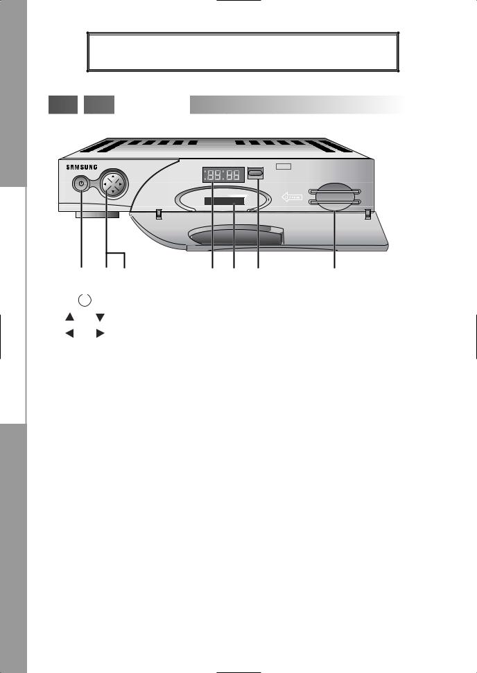
1. |
|
|
This key is for turning the receiver on and Standby. |
|
|
||
2. |
, |
These keys are for changing the channels. |
|
3. |
, |
These keys are for increasing and decreasing the volume level |
|
|
|
|
manually. |
4. 7 Segment Display This LED display will show the current channel number.
While the receiver is in Standby mode, the display will show the current time.
5. CA Module Slot In the slot you can use a CA module from a service provider of your own choice.
(For models DSR 9500AY, DSR 9510Y, DSR 9500AZ, DSR 9510Z)
6.Infrared Sensor This is to receive the IR commands from the Remote Control Unit.
7.Smart Card Slot The STB is equipped with a built in decoder for the CAS encryption.
DSR 9500AX, DSR 9500AY, DSR 9510Y and DSR 9510X models are valid for the Viaccess and CONAX smart card encryption at all. Only a CONAX smart card can be used for DSR 9500AZ and
DSR 9510Z.
Note : CA modules and smart cards are only distributed by service Providers
and special distributors, not by SAMSUNG.
GB-6
D I G I T A L S A T E L
DESCRIPTION


 Rear
Rear
 Panel
Panel


12 6 11 10 |
7 |
5 |
9 |
4 |
8 |
3 |
2 |
1 |
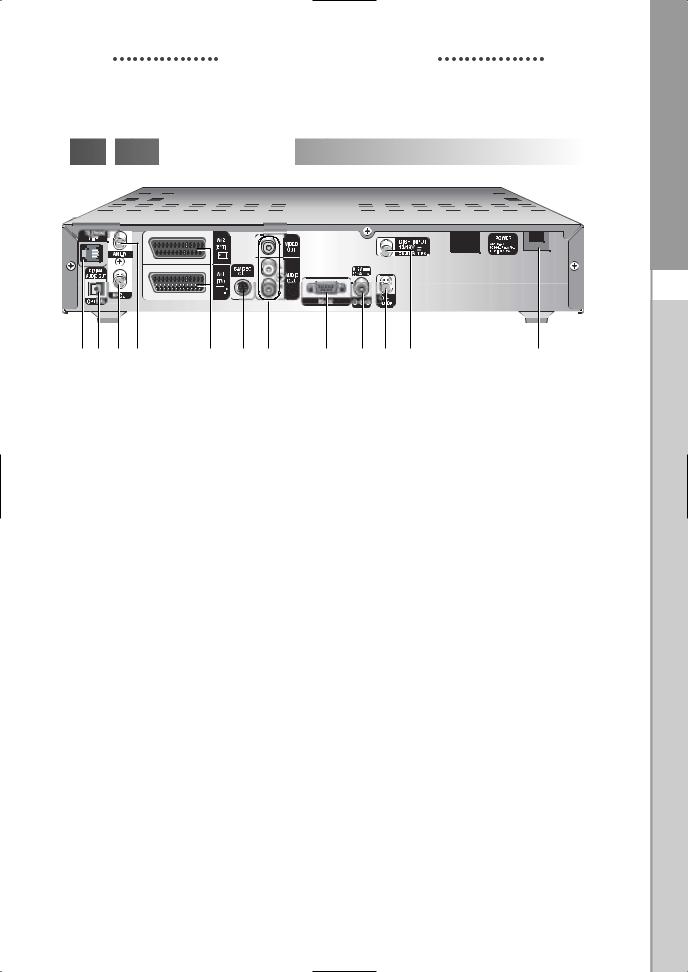
1. AC MAINS |
This is to plug in the AC mains power cord. |
|
The input AC voltage range is 100V to 240V, 50Hz/60Hz supply. |
2. LNB |
This port is to connect the coaxial cable from LNB of your dish. |
|
The IF input is provided through this port and the input frequency range |
|
is 950-2150 MHz. Also the voltage switching 13V and 18V is passed |
|
through this port. |
3. LOOP |
To enable the connection of an Analog receiver, The receiver is provided |
|
with this ‘LOOP’ port. |
4. RS 232 DATA PORT |
This is for connecting your receiver to a computer for reading and |
|
loading data information. This is for the external modem for future |
|
purposes only, too. |
5. S-VHS |
This is for connecting STB to your TV by using S-VHS cable. |
6. SPDIF |
Output for connection to a digital amplifier. |
7. AV SCARTS |
This is for connecting to your AV scarts for TV & VCR or DVD player. |
8. 0/12V |
This is for connecting to an external LNB switch. |
9. VIDEO, AUDIO R/L |
These RCA connectors are for connecting any external video |
|
and audio. |
10. ANT.IN |
This is for connecting your local RF channels to your TV through Loop. |
11. TV |
This is for connecting to your TV via RF cable. |
12. TELEPHONE LINE |
The telephone lead(labeled in the diagram above) is intended for |
|
connection to standard NORDIC telephone lines. |
|
(Only 3models can be used for DSR 9510X, DSR 9510Y |
|
and DSR 9510Z.) |
L I T E R E C E I V E R
GB-7
DESCRIPTION


 Remote
 Control
 Unit
Unit


1
2
3
9
10
13
15
16
POWER |
TV/RADIO |
|
MUTE |
|
FAV |
|
EPG |
timer |
LAST |
|
|
MENU |
EXIT |
|
CH+ |
4
5
6
7
8
12
11
14
17
18
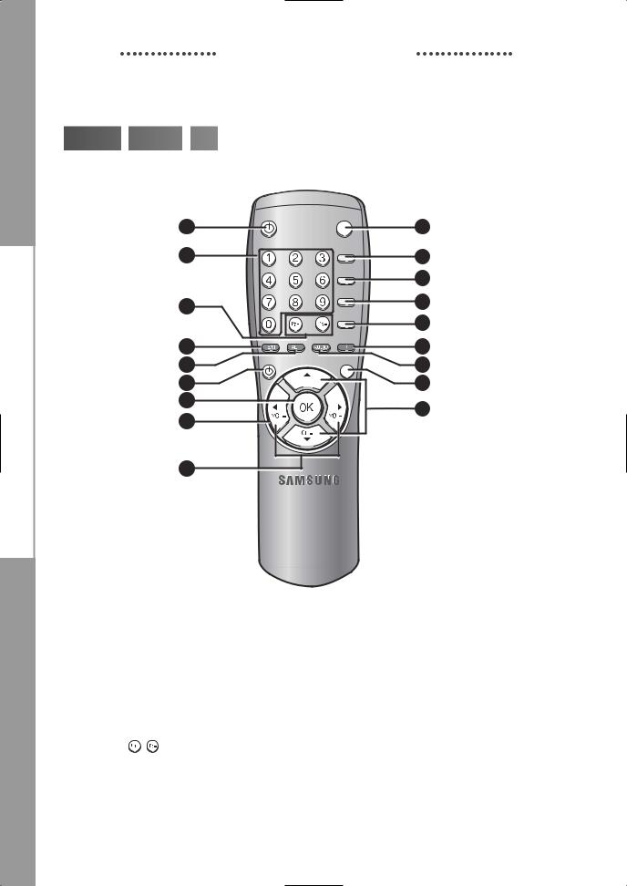
Note : When inserting batteries, make sure that the polarity(+/-) is correct.
1.POWER(  ) This is for switching the receiver ON/STANDBY mode.
2.0-9 Numerical keys ( ~
~ )
)
|
|
These keys are to enter numeric values and to select the channel |
|
|
directly by entering its number. |
3. |
Pg+/Pg- ( , |
) These keys are for moving up or down pages on the menu. |
4. |
TV/RADIO |
This key is for toggleing between the TV channel and Radio channel. |
5. |
MUTE |
This key is for toggleing between normal & muted audio. |
GB-8
D I G I T A L S A T E L
DESCRIPTION
6. |
FAV |
|
Use the key to switch between favorite lists. |
7. |
EPG |
|
Electronic Program Guide button displays the TV/Radio Program guide. |
8. |
LAST |
|
This key is for calling up directly whatever channel you were watching |
|
|
|
from the list. |
9. |
TEXT(GREEN) |
This key is for selecting the subtitle mode. |
|
|
( |
) |
This button functions same as the GREEN button on the menu. |
|
|
|
Press once and subtitle appears. You can select the language you want |
|
|
|
using the channel +/- keys. |
|
|
|
Press twice it. Then Teletext will be displayed on TV Screen without |
|
|
|
operating anything on TV. This Teletext can be displayed on TV which |
|
|
|
doesn't support Teletext functionality. |
|
|
|
Press three times it. Then Teletext will be available on TV. |
|
|
|
It means that Teletext can be chosen by TV with TV RCU. |
10. ALT(YELLOW) This key is for selecting the soundtrack list for the current service. ( ) This button functions same as the YELLOW button on the menu.
Press once and sound track appears. Press twice and video track appears.
The sound and video track services are not provided for every channel and depend on the conditions the operator is in.
11. AUDIO(BLUE) |
This key is for changing the Audio to the left, right or both channels, |
|
( |
) |
This button functions same as the BLUE button on the menu. |
12. INFORMATION This key is for displaying the programe information box in the screen. (RED) ( ) This button functions same as the RED button on the menu. Press
once and you can get simple information on the program. Press twice and you can get detailed information on the channel in text box.
13. |
MENU |
This key is for opening up the menu or returning to the previous menu. |
|
14. |
EXIT |
|
This key is for exiting a menu or returning to the previous menu. |
15. |
OK( |
) |
This key is for entering and confirming any data to the receiver in the |
|
|
|
menu system. This key is for selecting the item. Press while viewing |
|
|
|
TV and a list of channels is displayed. |
16. |
|
, |
These keys are for moving the highlight bar for selecting |
|
( |
, |
) options on the menu, and this button is used to change channels |
|
|
|
and increase or decrease the volume. |
17.CH+/CH-(  ) These keys are for changing channels.
18.VOL+/VOL-( 
 ) These keys are for increasing or decreasing the volume.
These keys are for moving up or down pages on the channel list.
L I T E R E C E I V E R
GB-9
 Loading...