


ROOM AIR CONDITIONER
INDOOR UNIT |
OUTDOOR UNIT |
AQ12SGGE |
UQ12SGGE |
SH12ZSG |
SH12ZSGX |
AQ09S8GE |
UQ09S8GE |
SH09ZS8 |
SH09ZS8X |
AQ07S8GE |
UQ07S8GE |
SH07ZS8 |
SH07ZS8X |
SERVICE Manual
AIR CONDITIONER |
CONTENTS |
|
1. Product Specifications |
|
2. Operating Instructions |
|
3. Disassembly and Reassembly |
|
4. Exploded Views and Parts List |
|
5. Block Diagrams |
|
6. PCB Diagrams |
|
7. Wiring Diagrams |
|
8. Schematic Diagrams |
1. Product Specifications
1-1 Table
|
|
|
|
|
Model |
SH12ZSG |
SH09ZS8 |
SH07ZS8 |
|||||||
|
|
|
|
|
AQ12SGGE |
AQ09S8GE |
AQ07S8GE |
||||||||
Item |
|
|
|
||||||||||||
|
|
|
Indoor unit |
|
|
Outdoor unit |
Indoor unit |
|
Outdoor unit |
Indoor unit |
Outdoor unit |
||||
|
|
|
|
|
|
|
|
|
|||||||
|
|
|
|
|
|
|
|
|
|
|
|
|
|||
Type |
|
|
|
Wall-mounting |
Wall-mounting |
Wall-mounting |
|||||||||
|
Cooling |
|
|
kW |
|
3.5 |
2.7 |
2.2 |
|||||||
|
|
|
|
|
|
|
|
|
|
|
|
|
|||
|
Heating |
|
|
kW |
|
3.8 |
2.9 |
2.3 |
|||||||
|
|
|
|
|
|
|
|
|
|
|
|
|
|||
|
Dehumiditying |
|
|
I/h |
|
1.9 |
1.4 |
0.9 |
|||||||
|
|
|
|
|
|
|
|
|
|
|
|
|
|
|
|
|
Air volume |
|
Cooling |
m3/min |
7.9 |
|
|
24 |
6.4 |
|
19 |
5.8 |
19 |
||
|
|
Heating |
8.6 |
|
|
|
24 |
7.0 |
|
19 |
6.2 |
19 |
|||
Perfor- |
|
|
|
|
|
||||||||||
mance |
|
|
|
Cooling |
dB |
40 |
|
|
|
50 |
38 |
|
48 |
36 |
47 |
|
Noise |
|
|
|
|
||||||||||
|
|
Heating |
40 |
|
|
|
50 |
38 |
|
48 |
36 |
47 |
|||
|
|
|
|
|
|
|
|
||||||||
|
Energy efficiency ratio |
Cooling |
W/W |
|
2.97 |
2.81 |
2.86 |
||||||||
|
|
|
|
|
|
|
|
|
|
|
|
||||
|
Heating |
|
3.25 |
3.22 |
3.29 |
||||||||||
|
|
|
|
|
|
||||||||||
|
|
|
|
|
|
|
|
|
|
|
|
||||
|
Power |
|
|
V-Hz |
1-220 / 240-50 |
1-220 / 240-50 |
1-220 / 240-50 |
||||||||
|
|
|
|
|
|
|
|
|
|
|
|
|
|||
|
Power Consumption |
Cooling |
W |
|
1180 |
960 |
770 |
||||||||
|
|
|
|
|
|
|
|
|
|
|
|
||||
|
Heating |
|
1170 |
900 |
700 |
||||||||||
|
|
|
|
|
|
||||||||||
|
|
|
|
|
|
|
|
|
|
|
|
|
|||
|
Operating Current |
Cooling |
A |
|
5.3 |
4.4 |
3.3 |
||||||||
|
|
|
|
|
|
|
|
|
|
|
|
||||
|
Heating |
|
5.1 |
4.0 |
3.1 |
||||||||||
|
|
|
|
|
|
||||||||||
|
|
|
|
|
|
|
|
|
|
|
|
|
|||
Power Power factor |
|
Cooling |
% |
|
96.8 |
94.9 |
99.9 |
||||||||
|
|
|
|
|
|
|
|
|
|
|
|
||||
|
Heating |
|
99.7 |
97.8 |
98.2 |
||||||||||
|
|
|
|
|
|
||||||||||
|
|
|
|
|
|
|
|
|
|
|
|
||||
|
Starting current |
|
A |
|
32.0 |
21.0 |
18.0 |
||||||||
|
|
|
|
|
|
|
|
|
|
|
|
|
|
|
|
|
|
|
|
Length |
m |
|
|
- |
|
|
|
- |
|
- |
|
|
Power cord |
|
|
|
|
|
|
|
|
|
|
|
|
|
|
|
|
Number of core wire |
|
|
- |
|
|
|
- |
|
- |
||||
|
|
|
|
|
|
|
|
|
|
|
|
||||
|
|
|
|
Capacity |
A |
250V-10 / 16A |
250V-10 / 16A |
250V-10 / 16A |
|||||||
|
|
|
|
|
|
|
|
|
|
|
|
|
|
|
|
|
Outer |
|
Width x Height |
mm |
890x285x179 |
|
|
695x530x280 |
795x258x179 |
|
660x475x242 |
795x258x179 |
660x475x242 |
||
|
|
|
|
|
|
|
|
|
|
|
|
|
|
|
|
|
Dimension |
|
x Depth |
inch |
35.0x11.2x7.0 |
|
|
27.4x20.9x11.0 |
31.3x10.2x7.0 |
|
26.0x18.7x9.5 |
31.3x10.2x7.0 |
26.0x18.7x9.5 |
||
|
|
|
|
|
|
|
|
|
|
|
|
|
|
|
|
|
Weight |
|
|
kg |
8.5 |
|
|
33.0 |
7.5 |
|
26.3 |
7.5 |
25.6 |
||
|
|
|
|
|
|
|
|
|
|
|
|
|
|||
|
Refrigerant pipe |
Liquid |
mm x L(MT) |
|
ø6.35 x 5 |
ø6.35 x 5 |
ø6.35 x 5 |
||||||||
|
|
|
|
GAS |
mm x L(MT) |
|
ø12.7 x 5 |
ø9.52 x 5 |
ø9.52 x 5 |
||||||
|
|
|
|
|
|
|
|
|
|
|
|
|
|||
Size |
Drain hose |
|
|
D x L(mm) |
|
ø18 x 2000 |
ø18 x 2000 |
ø18 x 2000 |
|||||||
|
|
|
|
|
|
|
|
|
|
|
|
|
|
|
|
|
|
Type |
|
|
|
Rotary |
Rotary |
Rotary |
|||||||
|
|
|
|
|
|
||||||||||
|
|
|
|
|
|
|
|
|
|
|
|
|
|
|
|
|
Compressor |
|
Motor |
Type |
|
- |
|
|
- |
- |
|
- |
- |
- |
|
|
|
|
|
|
|
|
|
|
|
|
|
|
|
|
|
|
|
|
|
Rated output |
|
- |
|
|
- |
- |
|
- |
- |
- |
|
|
|
|
Type |
|
|
Cross-flow |
|
|
Propeller |
Cross-flow |
|
Propeller |
Cross-flow |
Propeller |
|
|
|
|
|
|
|
|
|
|
|
|
|
|
|
|
|
|
Blower |
|
Motor |
Type |
|
steel |
|
|
|
steel |
steel |
|
steel |
steel |
steel |
|
|
|
|
|
|
|
|
|
|
|
|
|
|
|
|
|
|
|
|
Rated output |
W |
15 |
|
|
25 |
11 |
|
20 |
11 |
20 |
|
|
|
|
|
|
|
|
|
|
|
|
|
|
|
||
Heat exchanger |
|
|
|
2ROW 12STEP |
|
|
1ROW 20STEP |
2ROW 10STEP |
|
1ROW 18STEP |
2ROW 10STEP |
1ROW 18STEP |
|||
|
|
|
|
|
|
|
|
|
|
|
|||||
Refrigerant control unit |
|
|
|
CAPILLARY TUBE |
CAPILLARY TUBE |
CAPILLARY TUBE |
|||||||||
|
|
|
|
|
|
|
|
|
|
|
|
||||
Freezer oil capacity |
|
|
cc |
|
600 |
360 |
360 |
||||||||
|
|
|
|
|
|
|
|
|
|
|
|||||
Refrigerant to change(R-22) |
|
g |
|
820 |
660 |
620 |
|||||||||
|
|
|
|
|
|
|
|
|
|
|
|||||
Protection device |
|
|
|
RAC 12074-9622 |
RAC 12054-9622 |
RAC 12144-9622 |
|||||||||
|
|
|
|
|
|
|
|
|
|
|
|
|
|
||
Cooling test Condition |
|
|
|
INDOOR UNIT : DB27˚C WB19˚C |
|
OUTDOOR UNIT : DB35˚C |
WB24˚C |
||||||||
|
|
|
|
|
|
|
|
|
|
||||||
Maximum operation Condition |
|
|
INDOOR UNIT : DB32˚C WB23˚C |
|
OUTDOOR UNIT : DB43˚C |
WB26˚C |
|||||||||
|
|
|
|
|
|
|
|
|
|
|
|
|
|
|
|
Samsung Electronics |
1-1 |
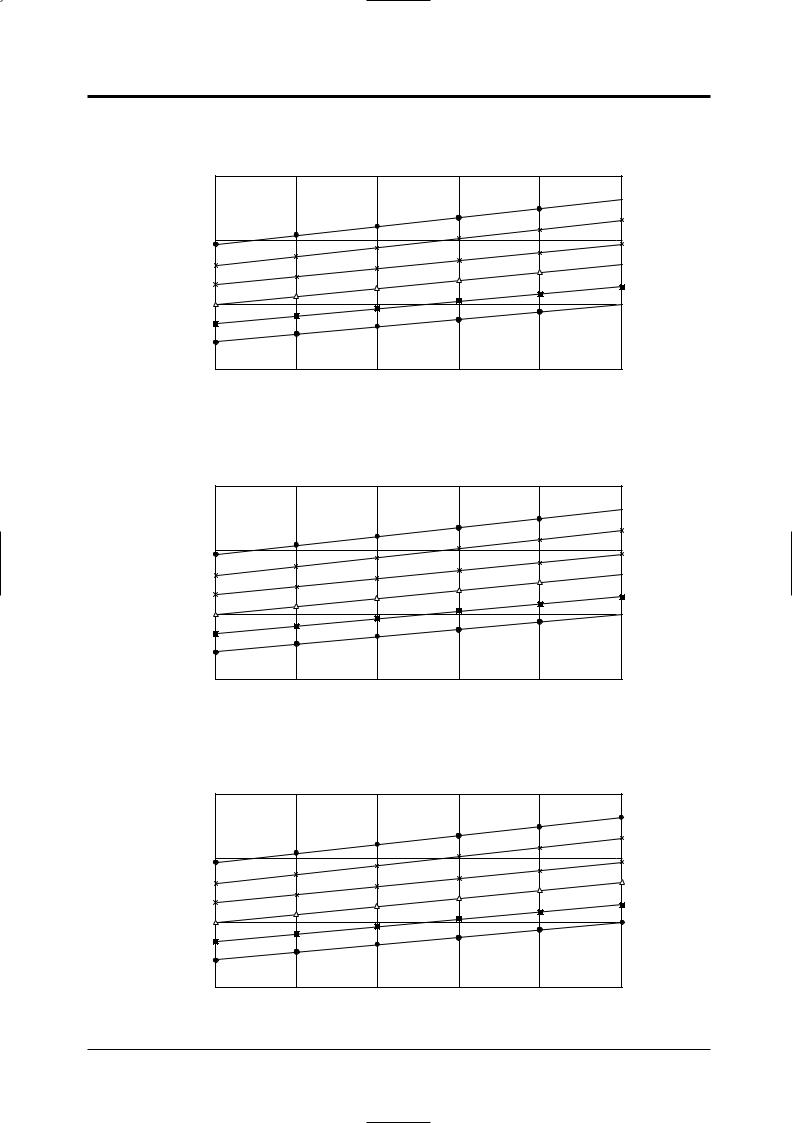
1-2 Pressure Graph
■ 12K BTU
6.5
5.5
4.5
3.5
20
■ 9K BTU
6.5 |
5.5 |
4.5 |
3.5 |
20 |
 32.4/24.0
30.6/22.5
28.8/21.0
 27.0/19.0
24.0/17.0
 21.5/15.0
25 |
30 |
35 |
40 |
45 |
 32.4/24.0
30.6/22.5
28.8/21.0
 27.0/19.0
24.0/17.0
 21.5/15.0
25 |
30 |
35 |
40 |
45 |
■ 7K BTU
7 |
|
|
|
|
|
|
|
|
|
|
|
|
32.4/24.0 |
|
|
|
|
|
|
30.6/22.5 |
6 |
|
|
|
|
|
28.8/21.0 |
|
|
|
|
|
|
27.0/19.0 |
|
|
|
|
|
|
24.0/17.0 |
5 |
|
|
|
|
|
21.5/15.0 |
4 |
20 |
25 |
30 |
35 |
40 |
45 |
1-2 |
Samsung Electronics |

2. Operating Instructions
2-1 The Feature of Key in remote control
NO |
NAMED OF KEY |
|
FUNCTION OF KEY |
|
|
1 |
|
Power On/Off button to start and stop air conditioner or timer set up. |
|
||
|
(UP) |
Temp. up button. To increase the temperature by the pressing |
|
||
|
the temperature button. |
|
|
||
|
|
|
|
||
2 |
|
|
|
|
|
|
(DOWN) |
Temp. down button. To decrease the temperature by the pressing |
|
||
|
the temperature button. |
|
|
||
|
|
|
|
||
|
|
Each time you press this button |
: Auto Mode |
: Fan Only |
|
3 |
|
Mode is changed in the following order |
: Cool Mode |
: Heat Mode |
|
|
|
|
|||
|
|
|
|
: Dry Mode |
|
|
|
Press the |
button one or more times until |
appears. The air conditioner |
|
|
|
cools or heats the room as quickly as possible. After 30minutes, |
|
||
|
|
the air conditioner is reset automatically to the previous mode. |
|
||
4 |
|
|
|
|
|
|
|
Press the |
button one or more times until |
appears. The sleep timer can be |
|
|
|
used when you are cooling or heating your room to switch the air conditioner off |
|||
|
|
automatically after a period of six hours. |
|
|
|
Each time you press this button,
FAN SPEED is changed in the following order.
5
6 |
Adjust air flow vertically. |
The ON Timer enables you to switch on the air conditioner automatically 7  after a given period of time that is from 30 minutes to 24 hours.
To cancel, press the 
 (Set/Cancel) button.
The Off Timer enables you to switch off the air conditioner automatically 8  after a given period of time that is from 30 minutes to 24 hours.
To cancel, press the 
 (Set/Cancel) button.
9 |
If you wish to save energy when using your air conditioner, select the Energy saving |
|
mode with the Energy saving button. |
||
|
Samsung Electronics |
2-1 |

Operating Instructions
2-1-1 Name & Function of Key in remote control
1.AUTO MODE : In this mode, operation mode(COOL, HEAT) is selected automatically by the room temperature of initial operation.
Room Temp |
Operation Type |
|
|
|
|
Tr≥ 21°C+∆ T |
Cool Operation (Set Temp:24˚C+∆ |
T) |
|
|
|
21°C +∆ T>Tr |
Heat Operation (Set Temp:22˚C+∆ |
T) |
|
|
|
∆T= -1°C, -2°C, 0°C+1°C+2°C
∆T is controlled by setting temperature up/down key of remote control
2.COOL MODE : The unit operates according to the difference between the setting and room temperature. (18°C~30°C)
3.HEAT MODE : The unit operates according to the difference between the setting and room temperature.(16°C~30°C)
*Prevention against cold wind : In order to prevent the cool air from flowing out at the heat mode, the indoor fan does not operate or operates very slowly in the following cases. At this time, the indoor heat exchanger will be preheating.
-For 3~5 minutes after the initial operation
-For deicing operation
-The operation of an indoor fan in accordance with the temperature of an indoor heat exchanger
The temperature of |
Indoor fan speed |
|
indoor heat exchanger |
||
|
||
|
|
|
below 28˚C |
off |
|
28˚C~below 34˚C |
LL Speed |
|
34˚C~below 40˚C |
L Speed |
|
above 40˚C |
Setting Speed |
*High temperature release function : It is a function to detect an outdoor overload by the sensor of an indoor heat exchanger and to turn the outdoor fan or the compressor ON/OFF for safety.
*Deice : Deicing operation is controlled by indoor unit's heat exchanger temperature and accumulating time of compressor's operation.
Deice ends by sensing of the processing time by deice condition.
4.DRY MODE : Has 3 states, each determined by room temperature.
The unit operates in DRY mode. *Compressor ON/OFF Time is controlled compulsorily(can not set up the fan speed, always breeze).
*Protective function : Low temperature release. (Prevention against freeze)
5.TURBO MODE : This mode is available in AUTO, COOL, HEAT, DRY, FAN MODE. When this button is pressed at first, the air conditioner is operated ìpowerfulî state for 30 minutes regardless of the set temperature, room temperature.
When this button is pressed again, or when the operating time is 30 minutes, turbo operation mode is canceled and returned to the previous mode.
*But, if you press the TURBO button in DRY or FAN mode that is changed with AUTO mode automatically.
6.SLEEP MODE : Sleep mode is available only in COOL or HEAT mode.
The operation will stop after 6 hours.
*In COOL mode : The setting temperature is automatically raised by 1°C each 1hour When the temperature has been raised by total of 2°C, that temperature is maintained.
*In HEAT mode : The setting temperature is automatically dropped by 1°C each 1hour.
When the temperature has been dropped by total of 2°C, that temperature is maintained.
2-2 |
Samsung Electronics |

7.FAN SPEED : Manual (3 step), Auto (4 step)
Fan speed automatically varies depending on both the difference between setting and the room temperature.
8.COMPULSORY OPERATION :
For operating the air conditioner without the remote control.
*The air conditioner starts up in the most suitable mode for the room temperature:
Room Temperature |
Operating Mode |
Temperature Setting |
Less than 21˚C |
Heat |
22˚C approx. |
21˚C or above |
Cool |
24˚C approx. |
|
|
|
9.SWING : BLADE-H is rotated vertically by the stepping motor.
*Swing Set : Press the  button under the remote control is displayed on LCD the
  and the blades move up and down. If the one more time press the
  button, blades location is stop.
10.SETTING THE ON/OFF TIMER. :
*ON TIMER : The On Timer enables you to switch on the air conditioner automatically after a given period of time. You can set the period of time from 30 minutes to 24 hours.
*OFF TIMER : The Off Timer enables you to switch off the air conditioner automatically after a given period of time. You can set the period of time from 30 minutes to 24 hours.
Operating Instructions
11. SELF DIAGNOSIS
|
LAMPof DISPLAYMonitor |
|
Description |
TURBO OPERATION TIMER |
ENERGY |
SAVING |
||
Indoor unit room temperature sensor error(open or short)
Indoor unit heat exchanger temperature sensor error(open or short)
Indoor fan motor malfunction
EEPROM error
Option error(option wasnít set up or option data error)
: Lamp off |
: Lamp flickering |
12.BUZZER SOUND : Whenever the ON/OFF button is pressed or whenever change occurs to the condition which is set up or select, the compulsory operation mode, buzzer is sounded "beep".
Samsung Electronics |
2-3 |

MEMO
2-4 |
Samsung Electronics |

3. Disassembly and Reassembly
Stop operation of the air conditioner and remove the power cord before repairing the unit.
3-1 Indoor Unit
No |
Parts |
|
Procedure |
Remark |
|
|
|
|
|
|
|
1 |
Front Grille |
1) |
Stop the air conditioner operation and block |
|
|
|
|
||||
|
|
|
the main power. |
|
|
|
|
2) |
Separate tape of front panel upper. |
|
|
|
|
|
|
|
|
3)Slide the lower front grille down, then disassemble it by pulling it forwards.
4)Open the upper front grille by pulling right and left sides of the grille.
5)Take the left and right filter out.
6)Loosen one of the right screw and separate the terminal cover.
7)Separate the thermistor from the front grille.
8)Loosen five fixing screws of front grille.
9)Pull the lower left and right of discharge softly for the outside cover to be pulled out.
10)In order to disassemble the panel grille, press, in order, the left, center, and right of the upper side of the panel grille with the palm of the hand to remove the hook.
And then disassemble the panel grille.
Samsung Electronics |
3-1 |
Disassembly and Reassembly
No |
Parts |
|
Procedure |
Remark |
|
|
|
|
|
|
|
2 |
Electrical Parts |
1) Do “1”, above. |
|
|
|
|
|
||||
|
(Main PCB) |
2) |
Take all the connector of PCB upper side out. |
|
|
|
|
|
|
||
|
|
|
(Inclusion Power cord) |
|
|
|
|
3) |
Separate the outdoor unit connection wire |
|
|
|
|
|
from the terminal block. |
|
|
|
|
4) |
If pulling the Main PCB up. it will be taken |
|
|
|
|
|
out. |
|
|
|
|
|
|
|
|
|
|
|
|
|
|
3 |
Ass’y Tray Drain. |
1) Do “1”, “2”, above. |
|
|
|
|
|
||||
|
|
|
Separate the drain hose from the extension |
|
|
|
|
|
drain hose. |
|
|
|
|
2) |
Pull tray drain out from the back body. |
|
|
|
|
|
|
|
|
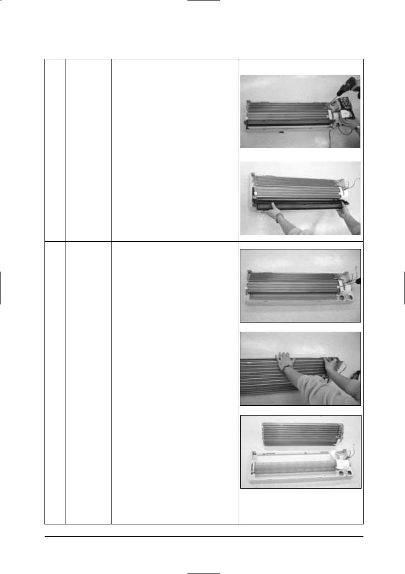
4 |
Heat Exchanger 1) Do “1” and “2”, “3”, above. |
2)Loosen two fixing earth screws of right side.
3)Separate the connection pipe.
4)Separate the holder pipe at the rearside.
5)Loosen the three fixing screws of right and left side.
6)Lifting the heat exchanger up a little to push the up side for separation from the indoor unit.
3-2 |
Samsung Electronics |

Disassembly and Reassembly
No |
Parts |
|
Procedure |
|
Remark |
|
|
|
|
|
|
|
|
5 |
Fan Motor and |
1) Do “1”, “2”, ”3”, “4”, above. |
|
|
|
|
|
|
|
||||
|
Cross Fan |
2) |
Loosen the fixing two screws and separate |
|
|
|
|
|
|
|
|
||
|
|
|
the motor holder. |
|
|
|
|
|
3) |
Loosen the fixing screw of fan motor. |
|
|
|
|
|
|
(By use of M3 wrench) |
|
|
|
|
|
4) |
Separate the fan motor from the fan. |
|
|
|
|
|
5) |
Separate the fan from the left holder bearing. |
|
|
|
|
|
|
|
|
||
|
|
|
|
|||
|
|
|
|
|
|
|
|
|
|
|
|
|
|
|
|
|
|
|
|
|
Samsung Electronics |
3-3 |
3-2 Outdoor Unit
•SH12ZSGX
•UQ12SGGE
No |
Parts |
|
Procedure |
Remark |
|
|
|
|
|
|
|
1 |
Common |
1) |
Loosen 2 fixing screws and separate the |
|
|
|
|
||||
|
Work |
|
cover valve. |
|
|
|
|
2) |
Separate the connection wire from the |
|
|
|
|
|
terminal block. |
|
|
|
|
|
|
|
|
3)Loosen 4 fixing srews and separate the cabi front.
4)Loosen 2 fixing screws and separate the cabi side LF.
5) Loosen 2 fixing screws of the cabi side RH.
2 |
Fan and |
1) |
Do “1”, above. |
|
Motor |
2) |
Separate the connection wire of the motor |
|
|
|
fan. |
3-4 |
Samsung Electronics |

Disassembly and Reassembly
No |
Parts |
Procedure |
Remark |
3)Remove the nut flange. (Turn to the right to remove, as it is a left hand screw)
4)Separate the fan.
5)Loosen 4 fixing screws to separate the motor.
6)Loosen 4 fixing screws and separate the motor bracket from the base.
3 |
Heat |
1) |
Do "1","2", above. |
|
Exchanger |
2) |
Loosen 2 fixing screws of left and right side. |
|
|
3) |
Disassemble the inlet and outlet pipe by |
|
|
|
welding. |
|
|
4) |
Separate the heat exchanger. |
4 |
Compressor |
1) Do "1","2","3", above. |
|
|
|
2) |
Open the terminal cover of compressor and |
|
|
|
unscrew the connection terminal. |
|
|
3) |
Disassemble the inlet and outlet pipe of |
|
|
|
compressor by welding. |
|
|
4) |
Loosen 3 fixing bolts of the lower part. |
|
|
5) |
Separate the compressor. |
Samsung Electronics |
3-5 |

Disassembly and Reassembly
•SH07ZS8X / SH09ZS8X
•UQ07S8GE / UQ09S8GE
No |
Parts |
Procedure |
Remark |
|
|
|
|
|
|
1 |
Common Work |
1) Loosen the fixing two screws and separate |
|
|
|
|
|||
|
|
the cover terminal. |
|
|
|
|
|
|
|
2)Loosen the fixing two screws and seperate the cover control.
3)Separate the connection wire from the terminal block.
4)Loosen six fixing screws and separate the cabi front.
5) Loosen the one fixing screw of assy E-part.
6)Loosen 12 fixing screws and separate the cabi side.
3-6 |
Samsung Electronics |

|
|
|
|
|
Disassembly and Reassembly |
|
|
|
|
|
|
|
|
No |
Parts |
|
Procedure |
|
Remark |
|
|
|
|
|
|
|
|
2 |
Fan and Motor |
1) Do “1”, above. |
|
|
|
|
|
|
|
||||
|
|
2) |
Remove the nut flange (Turn to the right to |
|
|
|
|
|
|
remove, as it is a left hand screw) |
|
|
|
|
|
3) |
Separate the fan. |
|
|
|
|
|
4) |
Loosen four fixing screws to separate the |
|
|
|
|
|
|
|
|
||
|
|
|
|
|
||
|
|
|
motor. |
|
|
|
|
|
5) |
Loosen two fixing screws and seperate the |
|
|
|
|
|
|
motor bracket from the base. |
|
|
|
|
|
|
|
|
|
|
|
|
|
|
|
|
|
3 |
Heat Exchanger |
1) Do “1”,“2”, above. |
|
|
|
|
|
|
|
||||
|
|
2) |
Loosen two fixing screws of left and right |
|
|
|
|
|
|
side. |
|
|
|
|
|
3) |
Disassemble the inlet and outlet pipe by |
|
|
|
|
|
|
welding. |
|
|
|
|
|
4) |
Separate the heat exchanger. |
|
|
|
|
|
|
|
|
|
|
|
|
|
|
|
|
|
4 |
Compressor |
1) Do “1”, “2”, “3”, above. |
|
|
|
|
|
|
|
||||
|
|
2) |
Open the terminal cover of compressor and |
|
|
|
|
|
|
unscrew the connection terminal. |
|
|
|
|
|
3) |
Disassemble the inlet and outlet pipe of |
|
|
|
|
|
|
compressor by welding. |
|
|
|
|
|
4) |
Loosen the three bolts of the lower part. |
|
|
|
|
|
5) |
Separate the compressor. |
|
|
|
|
|
|
|
|
|
|
|
|
|
|
|
|
|
|
|
|
|
|
|
|
|
|
|
|
|
|
|
|
|
|
|
|
|
|
Samsung Electronics |
3-7 |
 Loading...