


IMPORTADOR
Comercializadora Thomson de México, S.A. de C.V. Miguel de Cervantes Saavedra 57
Col. Ampliación Granada
C.P. 11529 Mexico D.F.
Telefono: (55)25 81 53 20
R.F.C.: CTM-980723-KS5
EXPORTER
Thomson Inc.
P.O. Box 1976 Indianapolis, IN 46206 - 1976 © 2003 Thomson Inc. Trademark(s) ® Registered Marca(s) Registrada(s) Marque(s) Deposée 55705620 (EN/F/E) www.rca.com www.rca.com/LatinAmerica
Printed in China / Impreso en China
0151

n a m r e s u
H O M E |
T H E A T E R |
A U D I O |
V I D E O |
R E C E I V E R |
|
||||
|
|
|
||
ON/STANDBY |
|
|
|
|
SOURCE |
|
|
|
|
|
FM/AM |
TUNING |
MEMORY |
|
|
|
|
||
MUTE |
|
|
|
|
SOURCE |
|
|
|
|
PHONES |
|
|
|
|
OK
|
VOLUME |
|
|
|
|
|
|
|
u |
|
SURR MODE |
|
|
LEVEL |
|
BASS/TREBLE |
|
||
|
|
a |
||
SETUP TEST TONE |
EQ DIGITAL INPUT |
|
|
|
|
|
|
||
|
DSP MODE |
|
|
|
|
ST / MONO |
|
L - AUDIO |
- R |
|
V-AUX |
VIDEO |
||
|
|
|||
|
|
|
|
l |
RT2360/RT2360BK
It is important to read this instruction book prior to using your new product for the first time. Es importante leer este manual antes de usar por vez primera su euipo.
FCC Information
This device complies with Part 15 of the FCC Rules. Operation is subject to the following two conditions: (1) This device may not cause harmful interference, and (2) this device must accept any interference received, including interference that may cause undesired operation.
In accordance with FCC requirements, changes or modifications not expressly approved by Thomson Inc. could void the user’s authority to operate this product.
This device generates and uses radio frequency (RF) energy, and if not installed and used properly, this equipment may cause interference to radio and television reception.
If this equipment does cause interference to radio or television reception (which you can determine by unplugging the unit), try to correct the interference by one or more of the following measures:
•Re-orient the receiving antenna (that is, the antenna for the radio or television that is
"receiving" the interference).
•Move the unit away from the equipment that is receiving interference.
•Plug the unit into a different wall outlet so that the unit and the equipment receiving interference are on different branch circuits.
If these measures do not eliminate the interference, please consult your dealer or an experienced radio/television technician for additional suggestions. Also, the Federal Communications
Commission has prepared a helpful booklet, "How To Identify and Resolve Radio TV Interference
Problems." This booklet is available from the U.S. Government Printing Office, Washington, DC 20402.
Please specify stock number 004-000-00345-4 when ordering copies.
This product complies with DHHS Rules 21 CFR Subchapter J. Applicable at the date of manufacture.
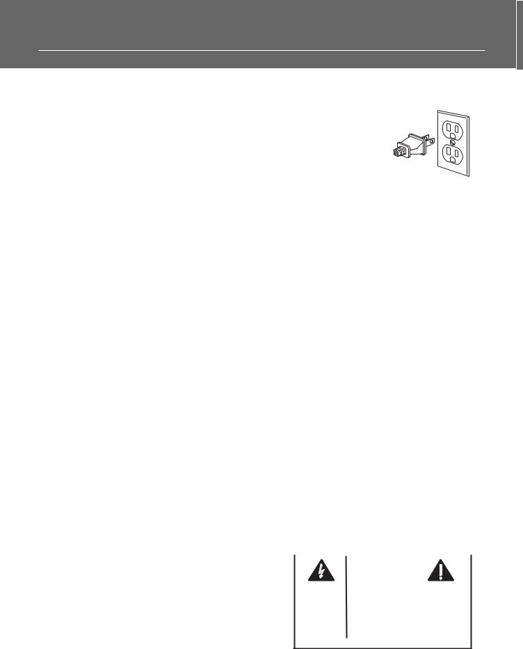
For Your Safety
The AC power plug is polarized (one blade is wider than the other) and only fits into
AC power outlets one way. If the plug won’t go into the outlet completely, turn the plug over and try to insert it the other way. If it still won’t fit, contact a qualified electri-
cian to change the outlet, or use a different one. Do not attempt to bypass this safety feature.
CAUTION: TO PREVENT ELECTRIC SHOCK,
MATCH WIDE BLADE OF PLUG TO WIDE SLOT,
FULLY INSERT.
For Your Records
In the event that service should be required, you may need both the model number and the serial number. In the space below, record the date and place of purchase, and the serial number:
Model No.
Remote Control No.
Date of Purchase
Place of Purchase
Serial No.
Service Information
This product should be serviced only by those specially trained in appropriate servicing techniques. For instructions on how to obtain service, refer to the warranty included in this Guide
Technical Specification
Product: Dolby Digital Audio video receiver Brand: RCA
Model: RT2360/RT2360BK
Electrical current consumption
Power Supply: 120V ~ 60Hz
Power consumption: 165 Watts
IMPORTER
Comercializadora Thomson de México, S.A. de C.V.
Miguel de Cervantes Saavedra No. 57 Col. Ampliación Granada
C.P. 11529 Mexico D.F. Telefono: (55)25 81 53 20 RFC: CTM-980723-KS5
|
|
|
|
|
|
|
|
|
|
|
|
CAUTION |
|
|
|
|
|
|
|
RISK OF ELECTRIC SHOCK |
|
|
|
|
|
|
|
DO NOT OPEN |
|
|
|
T H E L I G H T N I N G |
CAUTION: TO REDUCE THE |
THE EXCLAMATION |
|||||
FLASH AND ARROW- |
RISK OF ELECTRIC SHOCK, |
POINT WITHIN THE |
|||||
HEAD WITHIN THE |
D O N O T R E M O V E C O V E R |
T R I A N G L E |
I S A |
||||
T R I A N G L E |
I S |
A |
( O R B A C K ) . N O U S E R - |
WARNING |
SIGN |
||
W A R N I N G |
S I G N |
S E RV I C E A B L E PA R T S I N - |
ALERTING YOU OF |
||||
ALERTING YOU |
OF |
S I D E . R E F E R S E RV I C I N G |
I M P O R T A N T |
||||
" D A N G E R O U S |
T O Q U A L I F I E D S E R V I C E |
I N S T R U C T I O N S |
|||||
VOLTAGE" |
INSIDE |
PERSONNEL. |
A C C O M PA N Y I N G |
||||
THE PRODUCT. |
|
|
|
|
T H E P R O D U C T. |
||
|
|
|
|
|
|
|
|
SEE MARKING ON BOTTOM / BACK OF PRODUCT
WARNING:TO PREVENT FIRE OR ELECTRICAL SHOCK HAZARD, DO NOT EXPOSETHIS PRODUCT TO RAIN OR MOISTURE.

Table of Content
FCC Information
Getting Started
Unpacking the Receiver . . . . . . . . . . . . .2 Unpacking the Speakers . . . . . . . . . . . . .3 Inserting Batteries into Remote Control .3 Set Up and Maintenance of the
Receiver . . . . . . . . . . . . . . . . . . . . . . . . . .3 Protect your Components from Overheating . . . . . . . . . . . . . . . . . . . . . . .3 Connecting to Audio-Visual
Components . . . . . . . . . . . . . . . . . . . . . .4 Digital Connection . . . . . . . . . . . . . . . . .5 Connecting Antennas . . . . . . . . . . . . . . .5 Connecting the Speakers . . . . . . . . . . . . .6 Connecting the Subwoofer . . . . . . . . . . .6 Positioning your Speaker . . . . . . . . . . . . .7 Front Speaker Placement . . . . . . . . . . . . .7 Surround Placement . . . . . . . . . . . . . . . .8 Advanced Surround Setting . . . . . . . . . .8 Test Tone / Channel Balance . . . . . . . . . .9 Connecting for Power . . . . . . . . . . . . . . .9 Using Headphones . . . . . . . . . . . . . . . . . .9 Factory Setting . . . . . . . . . . . . . . . . . . . . .9
Operating your Receiver
Receiver Controls . . . . . . . . . . . . . . . . . .10 Your Remote Control . . . . . . . . . . . . . . .11 Display . . . . . . . . . . . . . . . . . . . . . . . . . .12 Switching On/Off . . . . . . . . . . . . . . . . . .13 Selection of Audio/Video Source . . . . . .13 Using the Remote to Control Additional Components . . . . . . . . . . . . . . . . . . . . . .14 Using the receiver to play a Source . . . .15 Operating the Radio . . . . . . . . . . . . . . .16
Advanced Sound Control
Sound Enhancement Systems . . . . . . . .18
Fine Setting of Components . . . . . . . . .19
Fine Setting of the Speakers . . . . . . . . .20
Advanced Setting . . . . . . . . . . . . . . . . .20
Troubleshooting Tips |
EN |
Troubleshooting Tips . . . . . . . . . . . . . . .22
Receiver/Tuner Operation . . . . . . . . . .22
Remote Control Operation . . . . . . . . .22
General . . . . . . . . . . . . . . . . . . . . . . . .22
Cleaning the Exterior . . . . . . . . . . . . .22
Equipment Specifications . . . . . . . . . .22
Care and Maintenance
Cleaning . . . . . . . . . . . . . . . . . . . . . . . . .23 Important battery information . . . . . . .23 Safety precautions . . . . . . . . . . . . . . . . .23 Headset safety . . . . . . . . . . . . . . . . . . . .23 Don’t infringe . . . . . . . . . . . . . . . . . . . .23
Remote Codes
Cable Codes . . . . . . . . . . . . . . . . . . . . . .24 VCR Codes . . . . . . . . . . . . . . . . . . . . . . .24 TV Codes . . . . . . . . . . . . . . . . . . . . . . . .25 Satellite Receivers . . . . . . . . . . . . . . . . .26 Audio (RCA only) . . . . . . . . . . . . . . . . . .26 Laser disc Players . . . . . . . . . . . . . . . . . .26
Limited Warranty (U.S.) . . . . . . . .27
Limited Warranty (Canada) . . . . .28
1
Getting Started
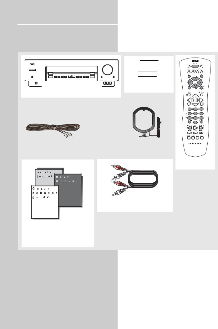
Unpacking the Receiver
You should receive the following items:
H O M E T H E A T E R A U D I O V I D E O R E C E I V E R |
VOLUME |
ON/STANDBY |
|
|
|
|
|
|
|
|
|
|
|
SOURCE |
|
|
|
|
|
|
SURR MODE |
|
|
MUTE |
FM/AM |
TUNING |
MEMORY |
SETUP |
TEST TONE |
EQ |
DIGITAL INPUT |
BASS/TREBLE |
LEVEL |
|
|
|
|
|
OK |
|
|
|
|
|
|
|
SOURCE |
|
|
|
|
|
|
DSP MODE |
|
|
|
|
|
|
|
|
|
ST / MONO |
|
|
|
|
PHONES |
|
|
|
|
|
|
V-AUX |
VIDEO |
L - AUDIO - R |
 + -
+ -
 + -
+ -
One pair of “AA”
batteries
One receiver unit
|
|
|
|
|
|
|
|
|
|
|
|
|
|
|
|
|
|
|
|
|
|
|
|
|
|
|
One external FM Dipole |
|
|
|
|
|
|||
|
|
|
|
|
||||
|
|
|
|
|
||||
|
|
|
|
|
||||
One external AM loop |
||||||||
antenna |
antenna |
|||||||
|
|
|
|
|
|
|
|
|
One RCA Universal
Remote Control
one audio cable (two wires) with red and white RCA connectors;
•one instruction book;
•one safety leaflet;
•one Quick Connection Guide
2
Getting Started
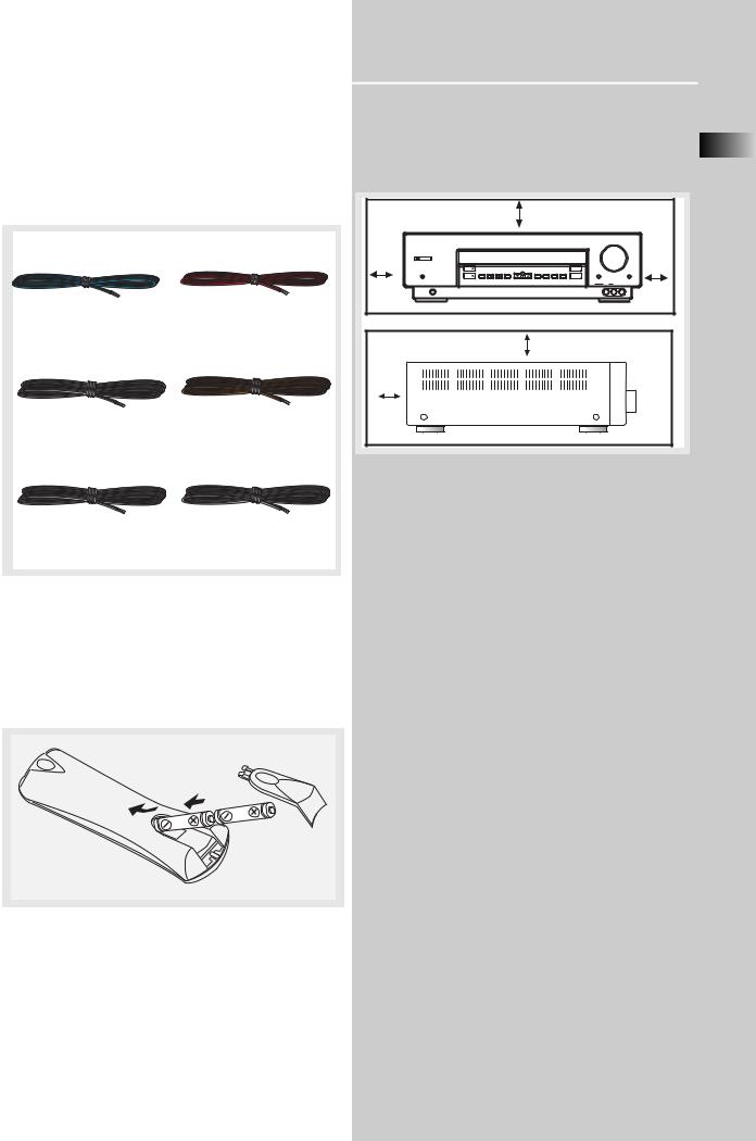
Unpacking The Speakers
•one set of speakers including 2 front speakers, 1 centre speaker, 1 subwoofer and 2 rear speakers.
•6 speaker wires including:
1 X green/black wire for center speaker
1 X white/black wire for front left speaker
1 X blue/black wire for rear left speaker
1 X red/black wire for front right speaker
1 X purple/black wire for subwoofer
1 X gray/black wire for rear right speaker
Inserting Batteries into Remote Control
Insert two AA(R6) batteries according to the + and - signs on the battery compartment. To use the remote control, point it directly at your receiver. Whenever a button is pressed, a red indicator will light up on the remote control.
Install batteries as follows:
1.Remove battery compartment door by applying thumb pressure on battery door and then lift the door out and off the cabinet.
2.Insert 2 AA batteries in the compartment and replace the compartment door.
Set up and Maintenance of the Receiver
EN
• Provide spaces for sufficient ventilation as indicated:
|
10 cm/4" |
|
H O M E T H E A T E R A U D I O V I D E O R E C E I V E R |
10 cm/ |
10 cm/ |
4" |
4" |
|
10 cm/4" |
5 cm/ |
|
2" |
|
•Do not connect to the AC power cords until all connections are completed.
•Do not use your set immediately after transferring it from a cold place to a warm place: there is risk of condensation.
•Do not expose your set to water and excessively high temperatures.
•After having disconnected your set, clean the case with a soft cloth, or with a slightly damp leather chamois. Never use strong solvents.
Protect your Components from
Overheating
•Do not block ventilation holes in any component.
Arrange the components so that air can circulate freely.
•Do not stack components directly on top of each other.
•Allow adequate ventilation when placing your components in a stand.
•Place an amplifier near the top shelf of the stand so heated air rising from it will not affect other components. If you have a satellite receiver, you should place it on the top shelf.
3

Getting Started
Connecting to Audio-Visual Components
DIGITAL CONNECTION
S-VIDEO
If your video component has a S-Video jack included, you can make use of it to enjoy enhanced video quality by connecting it to the relevant S-Video jack at the rear side of the receiver. One S-video cable is needed for each component. When S-Video cable is used, composite video (yellow RCA connector) cable must also be connected for VCR recording. Note: Before plugging in the optical cable or S-Video cable, make sure to match the shape of
the plug and jack, otherwise, you will not be able to plug in completely.
DVD
If you have a SAT receiver DVD player or CD player with a digital output, you can make use of an optical digital cable (not supplied) or coaxial digital cable (not supplied) to carry the audio portion of the signal and enjoy Dolby Digital sound quality. One optical or coaxial cable is needed for each SAT receiver, DVD player or CD player. When optical or coaxial cable is used, the analog audio cables are still needed if recording through a tape or VCR is desired. This receiver provides one optical and one coaxial digital input for the connection of your components. Please connect your components (e.g. DVD, SAT or CD) to the appropriate digital inputs and press DIGITAL INPUT to select the corresponding digital input source.
Note: Optical and coax cables carry only the audio portion of the signal. A video connection must also be established for a SAT receiver and DVD player. S-video provides the best connection for the video portion of the signal. Composite video (yellow RCA connector) can also be used. It is important that the same type of cable (S-video or composite) that is connected from the Home Theater to the TV is used to connect the SAT receiver or DVD player to the Home Theater.
to S-VIDEO OUT (DVD)
to VIDEO OUT (DVD)
DIGITAL INPUT
Connect components capable of outputing Dolby Digital (e.g. DVD or SAT) or standard PCM (CD) format digital signals. Read section on "Input Signal Setting" under "Advanced Sound Control" carefully to adjust the matching input settings.
OPTICAL 1 |
SUBWOOFER |
PREOUT |
CD Player
Tape Deck
to AUDIO OUT(DVD)
to AUDIO OUT (CD)
to LINE OUT (Tape Deck)
AUDIOto OUT (SAT) |
VIDEOto OUT (SAT) |
SAT |
VIDEOOUT (SAT) |
||
|
|
TV |
|
|
to S |
to S-VIDEO IN (TV)
|
|
|
|
to VIDEO IN (TV) |
|
|
|
|
to AUDIO OUT (TV) |
AUDIO OUT (VCR) |
VIDEO OUT (VCR) |
to AUDIO IN (VCR) |
to VIDEO IN (VCR) |
VCR |
to |
to |
|
|
|
to LINE IN ( Tape Deck )
If your CD player is equipped with digital optical jacks, use of optical cable is preferred. What you need is just one more optical digital connecting cable (not supplied). Plug it in the digital input jack of the receiver and select OPTICAL on the receiver setting (see details on pg 19 chapter "Input Signal Setting"). You can enjoy better sound quality brought to you by the optical cable. When optical cable is used, analog cables are still needed for recording to tape output.
FRONT TERMINAL
Remark: If you have a video camera, video game machine, or an extra VCR, connect it to VAUX input at the front of the receiver
4
Getting Started
Digital Connections
Read instructions carefully when connecting components to the receiver.
Digital In Jacks can accept Dolby Digital (AC-3), DTS or PCM signals when compatible components are connected.
COAXIAL DIGITAL IN (AUDIO)
Connect to coaxial digital output of DVD, CD, SAT or other compatible devices.
|
DVD / CD / SAT |
|
OPTICAL DIGITAL IN (AUDIO) |
|
Optical Fiber Cable |
|
Connect to optical digital output of |
|
DVD, CD, SAT or other compatible |
OPTICAL 1 |
devices. |
|
SAT / DVD / CD Player / TV |
OPTICAL 1 |
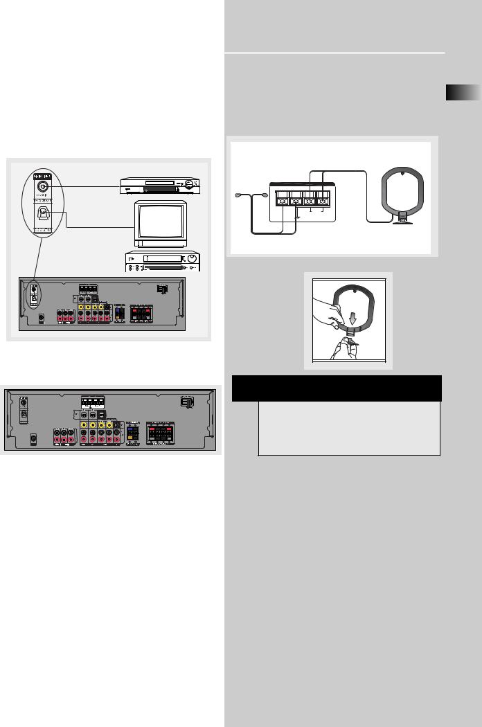
AM Loop Antenna and FM Indoor Antenna
1. Uncoil the Antenna wire and locate the base end
of the AM antenna and snap into place as shown EN below in AM Loop Antenna.
2. Press down on the Antenna tab to open the terminal
|
ANTENNA |
FM |
AM |
75Ω |
LOOP |
AM Loop Antenna
Connecting the Antennas
OPTICAL 1 |
SUBWOOFER |
PREOUT |
The AM and FM antennas connect to the AM and FM terminals on the system’s back panel.
They must be hooked up in order to receive clear reception.
HINT
•For FM reception, extend antenna to its full length and arrange the Antenna as a T Shape
•For AM reception, rotate the antenna horizontally to get better reception.
5
Getting Started
Connecting the Speakers
CENTER
SPEAKERS
CENTER
+ |
- |
GREEN / BLACK
CENTER
Use this jack on the left back panel
to connect another active subwoofer
other than the one
supplied.
SUB WOOFER
SPEAKER
PURPLE / BLACK
FRONT SPEAKERS
RIGHT |
LEFT |
||
+ |
- |
- |
+ |
|
BLACK / RED |
|
BLACK / WHITE |
|
FRONT |
|
|
|
|
|
BLACK / GREY |
|
BLACK / BLUE |
+ |
- |
+ |
- |
- |
+ |
|
|
REAR |
REAR |
||
SUB WOOFER |
REAR SPEAKERS |
(SURROUND SOUND) |
Speakers
There are 6 speakers equipped with the unit (2 front,
1 center, 2 rear, 1 subwoofer). In order to enjoy good surround effects, all six speakers need to be connected to the receiver.
At least two front speakers (left and right) are required. For better sound quality, Center speaker, rear speakers and Subwoofer should also be connected. Adding center and rear speakers will enhance surround effects. Adding a Subwoofer will increase bass response.
If you want to enjoy full range of sound effects, with small speakers, it is a must to use the subwoofer with the speakers to maintain adequate bass signal.
Speaker wires
1 for each speaker, is
needed for connection. Twist the stripped ends of speaker cord about 2/3 inch (15 mm). Press down on the tab to open the terminal and insert the wire. Release tab to lock wire in the
terminal.
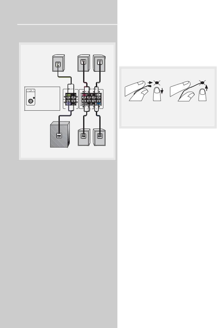
Antenna and Speaker Wire Connection
|
|
|
|
|
|
|
|
|
|
|
|
|
|
|
|
|
|
|
|
|
|
|
|
|
|
|
|
Push terminal tab down to |
Release tab to lock wire in |
|||||
insert wire. |
the terminal. |
|||||
NOTE: Make sure the insulation is completely removed from the ends of the Antenna and speaker wires at all connection points.
To ease speaker connections, the speaker wires and the terminals are color-coded.
•White/Black (Front Left Speaker),
•Red/Black (Front Right Speaker),
•Green/Black (Center Speaker)
•Blue/Black (Rear Left Speaker).
•Grey/Black (Rear Right Speaker).
•Purple/Black (Subwoofer)
Connect the L, R speakers at the back of the speakers to the corresponding color on the receiver. Do the same for center (with green/black terminal), rear speaker and the subwoofer (with purple/black terminal).
Speaker Polarity
When connecting the speakers, make sure the polarities (“+” speaker wire to “+” on the receiver) of speaker wires and terminals are matched. If the wires are reversed, the sound will be distorted and will lack bass (“out of phase” effect).
Connecting the Subwoofer
Connect the subwoofer with the speaker wire (purple/ black) provided.
This receiver offers a high flexibility for user to use a large variety of speakers and subwoofers. For more information please refer to section “Fine Setting of the Speakers” in “Advanced Sound Control” on page
20.
6
Getting Started
Positioning your speaker
1 Left, Right (Front Speakers)
They carry primarily music and sound effects
2 Center
In surround mode, the center speaker carries much of the dialogue as well as music and effects. It should be set between the left and right speakers.
3 Surround (Rear Speakers)
Their overall sound balance should be as close as possible to the front speakers. Proper placement is vital to establish an evenly distributed sound field.
Subwoofer
A subwoofer is designed to reproduce powerful low bass effects (explosions, the rumble of spaceships, etc.) which dramatically heightens involvement with the action on the screen. It is therefore recommended to connect subwoofers when small speakers are used.
Magnetic shielding
Speakers placed less than two feet from the TV set must be magnetically shielded in order to prevent picture distortion. Front and center speakers provided with this unit are magnetically shielded to protect your TV set.
It is not recommended to place the rear speakers near the TV set.
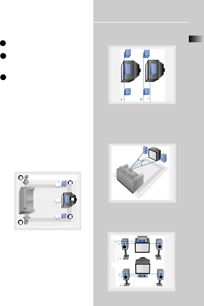
Alignment
Align the center speaker evenly with (A), or slightly behind (B), the left and right speakers, but not ahead EN of them.
Courtesy Dolby Laboratories
Advanced Setting
Angle
Placing the left and right speakers to form a 45degree angle with your favorite viewing position will duplicate the soundtrack mixer's perspective.
3
1
2
3
Courtesy Dolby Laboratories
Courtesy Dolby Laboratories
Height
The three speakers should be as close as possible to the same height. This often requires placing the center speaker directly atop (A) or beneath (B) the TV set.
A
Front Speaker Placement
Even if you can't duplicate this ideal home theater |
|
setup exactly, the suggestions for speaker placement |
|
that follow will help you get good results. |
B |
Courtesy Dolby Laboratories |
7 |
 Loading...