


owner’s manual
Audio/Video Receiver

INTRODUCTION
The RCA STAV–3860 has these great features.
Five Channels of Independent Amplification — five independent power amplifiers, each rated at 60W, ensure accurate, dynamic reproduction of all multi-channel material.
Dolby* Pro Logic — enjoy stunning multi-channel, surround sound effects from movies and other material recorded in Dolby Surround/Pro Logic. Enhance your listening experience further with built-in signal processing that recreates the movie theater ambience in your living room.
Digital Surround Effects — using Digital Signal Processing (DSP) technology, various listening environments, such as a theater or a jazz club, may be simulated and applied to any music or video source.
DVD 5.1 Channel Input — a special 5.1 Channel input makes the STAV-3860 fully compatible with Dolby Digital decoders and DVD players with 5.1 channel outputs.
The Energy-saving Design — this unit is designed to use minimal electricity when power is switched OFF (in Standby mode). Regarding the value of the power consumption in standby mode, refer to “Specifications” on pages 31.
Note to the Cable TV System Installer:
This reminder is provided to call the CATV system installer's attention to Article 820-40 of the National Electrical Code that provides guidelines for proper grounding and, in particular, specifies that the cable ground shall be connected to the grounding system of the building as close to the point of cable entry as practical.
* Manufactured under license from Dolby Laboratories.
"Dolby", "Pro Logic" and the double-D symbol are trademarks of Dolby Laboratories. Confidential unpublished works. © 1992-1997 Dolby Laboratories.All rights reserved.
©1999 Tandy Corporation.
All Rights Reserved.
2
IMPORTANT SAFETY INSTRUCTIONS
This receiver is made and tested to meet exacting safety standards. It meets both UL and FCC requirements and complies with safety performance standards of the US Department of Health and Human Services.
WARNING: TO REDUCE THE RISK OF FIRE OR ELECTRIC SHOCK, DO NOT EXPOSE THIS APPLIANCE TO RAIN OR MOISTURE.
CAUTION |
RISK OF ELECTRIC SHOCK. |
DO NOT OPEN. |
CAUTION: TO REDUCE THE RISK OF ELECTRIC SHOCK, DO NOT REMOVE THE COVER. NO USER-SERVICEABLE PARTS INSIDE. REFER SERVICING TO QUALIFIED SERVICE PERSONNEL.
This symbol is intended to alert you to the presence of dangerous voltage inside the product that can cause shock. Do not open the product’s case.
This symbol is intended to alert you to important operating and maintenance instructions in this owner’s manual.
Careful attention is devoted to quality standards in the manufacture of your cassette deck, and safety is a major factor in its design. However, safety is also your responsibility.
This section lists important information that will help you properly use and enjoy your cassette deck and accessories. Read all the included safety and operating instructions before using your cassette deck, follow them closely, and retain them for future reference.
Heed Warnings — Follow all warnings on the product and in the operating instructions.
Cleaning — Unplug this product from the wall outlet before cleaning. Use only a damp cloth for cleaning. Do not use liquid or aerosol cleaners.
Attachments — Do not use attachments/accessories not recommended by the product manufacturer, as they might create a hazard.
Water and Moisture — Do not use this product near water (for example, near a bathtub, washbowl, kitchen sink, or laundry tub; in a wet basement; or near a swimming pool).
Accessories — Do not place this product on an unstable cart, stand, tripod, bracket, or table. The product may fall, causing serious injury to a child or adult, and serious damage to the product. Use only with a cart, stand, tripod, bracket, or table recommended by the manufacturer or sold with the product. Follow the manufacturer’s instructions for mounting, and use a recommended mounting accessory.
Carts — Move the product on a cart carefully. Quick stops, excessive force, and uneven surfaces may cause the product/cart to overturn.
Ventilation — Slots and openings in the cabinet provide ventilation, ensure reliable operation, and protect from overheating. Do not block or cover these openings, and do not place the product on a bed, sofa, rug, or other similar surface. Do not place the product in a built-in bookcase or rack unless it provides proper ventilation as specified by the manufacturer.
Power Sources — Operate this product using only the power source indicated on its marking label. If you are not sure of your home’s power type, consult your product dealer or local power company.
Polarization — This product is equipped with a polarized AC line plug (a plug having one blade wider than the other). This plug will fit in the power outlet only one way. This is a safety feature. If you cannot insert the plug fully into the outlet, try reversing the plug. If the plug still doesn’t fit, contact your electrician to replace your obsolete outlet. Do not defeat the safety purpose of the polarized plug. If you need an extension, use a polarized cord.
Power-Cord Protection — Route power-supply cords so they are not likely to be walked on or pinched by items placed on or against them, paying particular attention to cords at plugs, convenience receptacles, and the point where they exit from the product.
Lightning — For added protection for this product during a lightning storm, or when it is left unattended and unused for long periods of time, unplug it from the wall outlet and disconnect the antenna or cable system. This will prevent damage to the product due to lightning and power-line surges.
Overloading — Do not overload wall outlets, extension cords, or integral convenience receptacles, as this can result in a risk of fire or electric shock.
Objects and Liquids — Never push objects of any kind into this product through openings, as they may touch dangerous voltage points or short out parts that could result in a fire or electric shock. Never spill liquid of any kind on the product.
Servicing — Do not attempt to service this product yourself, as opening or removing covers may expose you to dangerous voltage or other hazards. Refer all servicing to qualified service personnel.
Damage Requiring Service — Unplug this product from the wall outlet and refer servicing to qualified service personnel under the following conditions:
•When the power-supply cord or plug is damaged.
•If liquid has been spilled or objects have fallen into the product.
•If the product has been exposed to rain or water.
•If the product does not operate normally by following the operating instructions. Adjust only those controls that are covered by the operating instructions, as an improper adjustment of other controls may result in damage and will often require extensive work by a qualified technician to restore the product to normal operation.
•If the product has been dropped or damaged in any way.
•When the product exhibits a distinct change in performance.
Replacement Parts — When replacement parts are required, be sure the service technician uses replacement parts specified by the manufacturer or having the same characteristics as the original part. Unauthorized substitutions may result in fire, electric shock, or other hazards.
Safety Check — Upon completion of service or repairs to this product, ask the service technician to perform safety checks to determine that the product is in proper operating condition.
Wall or Ceiling Mount — The product should be mounted to a wall or ceiling only as recommended by the manufacturer.
Heat — The product should be situated away from heat sources such as radiators, heat registers, stoves, or other products (including amplifiers) that produce heat.
3

Warning: This receiver uses a laser. Because of possible eye injury, only a qualified service person should remove the cover or attempt to service this device.
Cautions
∙The use of controls or adjustments, or the per formance of procedures other than specified herein, can result in hazardous exposure to laser light.
∙To prevent electric shock do not use this polarized plug with an extension cord, receptacle, or other outlet unless the blades can be fully inserted to prevent blade exposure.
4

TABLE OF CONTENTS |
|
Preparation ....................................................................................................... |
6 |
Checking the Supplied Accessories ............................................................................................. |
6 |
Using this Manual ....................................................................................................................... |
6 |
Installing the Receiver ................................................................................................................. |
6 |
Preparing the Remote Control ..................................................................................................... |
7 |
Connecting Your System .................................................................................... |
8 |
Connecting Antennas .................................................................................................................. |
8 |
Connecting Audio Components .................................................................................................. |
9 |
Connecting DVD 5.1 Channel Components .............................................................................. |
10 |
Connecting Video Components ................................................................................................ |
10 |
Connecting Speakers ................................................................................................................. |
11 |
AC Outlet ................................................................................................................................. |
12 |
Setting Up for Surround Sound ....................................................................... |
13 |
Setting Up for Surround Sound ................................................................................................. |
13 |
Displays and Controls ..................................................................................... |
17 |
Front Panel ............................................................................................................................... |
17 |
Display ...................................................................................................................................... |
18 |
Remote Control ......................................................................................................................... |
19 |
Listening in Surround Sound .......................................................................... |
20 |
Listening in Dolby Pro Logic Mode ........................................................................................... |
20 |
Listening in DVD 5.1 Channel Input Mode ............................................................................... |
21 |
Listening in DSP Mode .............................................................................................................. |
22 |
Using the Tuner ............................................................................................... |
23 |
Finding a Station ....................................................................................................................... |
23 |
Tuning Directly to a Station ....................................................................................................... |
24 |
Memorizing Stations ................................................................................................................. |
24 |
Recalling Memorized Stations ................................................................................................... |
25 |
Making a Recording......................................................................................... |
26 |
Making an Audio or Video Recording ....................................................................................... |
26 |
Additional System Control .............................................................................. |
27 |
CD Player Controls ................................................................................................................... |
27 |
Cassette Deck Controls ............................................................................................................. |
28 |
Additional Information ................................................................................... |
29 |
Troubleshooting ........................................................................................................................ |
29 |
Specifications ............................................................................................................................ |
31 |
5
PREPARATION
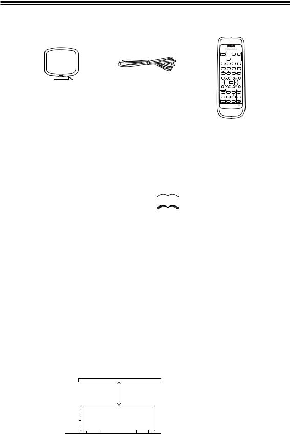
CHECKING THE SUPPLIED ACCESSORIES
Please check that you've received the following supplied accessories:
SOURCE
POWER
TAPE
$ ASMS $
1 2
CD TUNER
SOURCE SELECT
!SEARCH !
3 4
|
|
@ |
* DECK2 & |
# |
|
|
|
5 |
6 |
7 |
8 |
|
|
EFFECT |
DISC/STATION |
||
|
|
9 |
0 |
@ |
# |
|
|
D. ACCESS |
|
|
CLASS |
|
|
|
|
TUNING |
|
|
|
|
|
DECK1 |
|
|
|
|
|
& |
|
|
|
T.TONE |
|
|
MPX |
|
|
FM/AM |
|
|
|
AM Loop Antenna |
FM Wire Antenna |
|
|
TUNING |
|
SORROUND |
2 |
DSP MODE MUTING |
|||
|
|
CH SELECT |
|
LEVEL |
|
|
|
RECEIVER |
|
FL |
|
|
|
FUNCTION DIMMER VOLUME |
|||
|
|
POWER |
|
|
|
|
|
STAV-3860 |
|
|
|
|
|
AUDIO/VIDEO SYSTEM REMOTE OSR |
|||
Remote Control Unit
USING THIS MANUAL
This manual is for the STAV-3860 audio/video receiver. It is divided into two main sections:
Set up |
|
The following symbols are used |
|
This section covers installing your receiver and |
|
throughout this manual: |
|
connecting all the other components in your |
|
|
|
home theater system to it. It also describes how |
|
Provides detailed precautions and |
|
to set up a multi-channel speaker system to take |
memo |
||
advice on operations, etc. |
|||
full advantage of the great surround sound |
|
||
|
|
||
features of your receiver. |
|
|
Operation
This section shows you how to use every feature of the receiver and its remote control unit. It also covers using the supplied remote control to operate your other home theater components. To find out more about a specific button, control or indicator, see Displays and Controls starting on page 17. This will point you to the relevant chapter in the manual.
In the Additional Information section (p.29–31) you'll find a troubleshooting section and specifications.
INSTALLING THE RECEIVER
Notes:
 Indicates that display is blinking.
•Do not place objects directly on top of this unit. This would prevent proper heat dispersal.
•When installing in a rack, shelf, etc., be sure to leave more than 8 inches of space above the receiver.
8 INCHES
RECEIVER
6
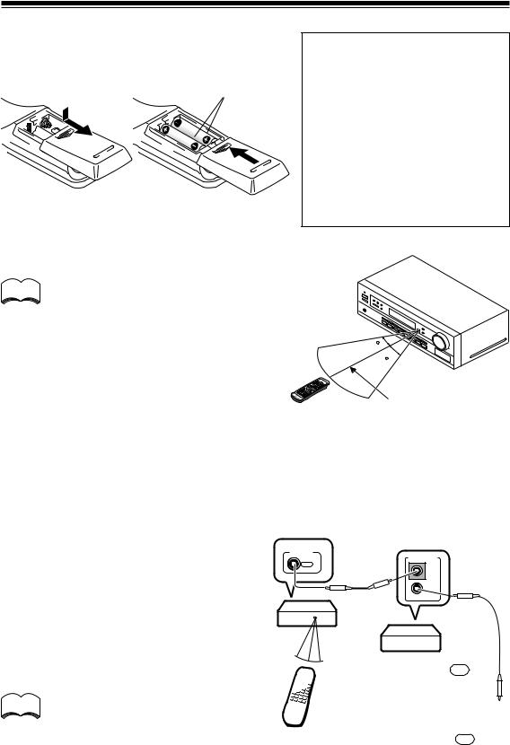
PREPARING THE REMOTE CONTROL
Loading the batteries
Dry Cell Batteries (not included)
(AA size IEC R6P x 2)
Operating Range of Remote Control Unit
The remote control may not work properly if:
memo |
• There are obstacles between the remote |
|
control and the receiver's remote sensor. |
||
|
•Direct sunlight or fluorescent light is shining onto the remote sensor.
•The receiver is located near a device that is emitting infrared rays.
•The receiver is operated simultaneously with another infrared remote control unit.
CAUTION:
Incorrect use of batteries may result in such hazards as leakage and bursting. Observe the following precautions:
•Never use new and old batteries to gether.
•Insert the plus and minus sides of the batteries properly according to the marks in the battery case.
•Batteries with the same shape may have different voltages. Do not use different batteries together.
30
30
23 ft.
The FUNCTION & SOURCE SELECT Buttons on the Remote Control
Please note that the remote control has two types of buttons, one called FUNCTION and a set of buttons called SOURCE SELECT. Use the FUNCTION button to choose the component you want to listen to (CD, CDR/TAPE, TUNER, etc.) and use the SOURCE SELECT buttons to change which component the remote control itself will operate. Thus, if the STAV-3860 is in TUNER mode, for example, and you want to listen to your CD player, you need to select the CD mode with the FUNCTION button.
Operating other RCA Components
CONTROL
By connecting a control cord (optional), you can
OUT
control other RCA professional series equipment using this remote control unit. Point the remote control unit towards the remote sensor of this unit, even when operating other equipment.
STAV-3860
The remote control signals are received by the remote sensor of this unit, and sent to the other devices via the CONTROL OUT terminal.
memo
You can also control RCA professional series components by pointing the
receiver's remote control directly at the
REMOTE CONTROL UNIT
component. This type of operation does not require control cords.
CONTROL
IN
OUT
OTHER RCA PROFESSIONAL
SERIES PRODUCTS WITH OSR
MARK
CONNECT TO CONTROL IN
TERMINAL OF OTHER RCA
PROFESSIONAL SERIES
PRODUCTS WITH OSR MARK.
7
CONNECTING YOUR SYSTEM
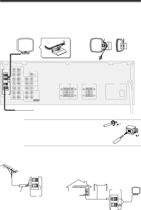
CONNECTING ANTENNAS
Connect the AM loop antenna and the FM wire antenna as shown below. To improve reception and sound quality, connect external antennas (see Using external antennas, below). Always make sure that the receiver is switched off and unplugged from the wall outlet before making or changing any connections.
AM Loop Antenna
Assemble the antenna and connect to the receiver. Attach to a wall, etc. (if desired) and face in the direction that gives the best reception.
R |
L |
|
AM LOOP |
|
|
ANTENNA IN |
CD |
|
|
|
CONTROL |
O |
|
|
U |
|
OUT |
T |
VCR/ |
|
|
|
|
|
DVR |
|
IN |
IN |
OUT |
|
IN |
TV/ |
IN |
TO |
FRONT |
CENTER |
|
MONITOR |
|||||
|
|
SAT |
|
TV |
SPEAKERS |
SPEAKER |
|
|
DVD |
|
SUB |
R |
L |
|
IN |
/LD |
IN |
WOOFER |
|
|
|
|
FRONT |
PREOUT |
|
|
|
FM |
|
|
|
SURROUND |
|
|
UNBAL |
R |
OUT |
R |
L |
|
|
75Ω |
E |
|
|
|||
C |
CD-R |
|
|
|||
FM |
|
|
|
|
|
|
|
/TAPE |
|
|
|
|
|
ANTENNA |
P |
/MD |
|
|
|
|
|
L |
IN |
|
CENTER |
|
|
|
A |
|
|
|
||
|
Y |
|
SUB |
|
|
|
|
|
|
DVD 5.1 CH |
|
|
|
|
|
|
WOOFER |
INPUT |
|
|
SURROUND |
AC OUTLET |
||
SPEAKERS |
|||
|
|||
R |
L |
|
|
FM Wire Antenna
Connect the FM wire antenna and fully extend vertically along a window frame or other suitable area.
Antenna Snap Connectors
Twist the exposed wire strands together and insert into  3/8 In. the hole, then snap the connector shut.
Using External Antennas |
|
7To Improve FM Reception |
7To Improve AM Reception |
Connect an external FM antenna. |
Connect a 15–18 feet length of vinyl-coated wire to the AM |
|
antenna terminal without disconnecting the supplied AM loop |
|
antenna. |
|
For the best possible reception, suspend horizontally outdoors. |
|
OUTDOOR ANTENNA |
75 Ω COAXIAL CABLE
|
AM LOOP |
FM |
ANTENNA |
UNBAL |
INDOOR ANTENNA |
75Ω |
|
FM |
(VINYL-COATED WIRE) |
ANTENNA |
|
|
15–18 FT |
8
CONNECTING AUDIO COMPONENTS
Connect your audio components as shown below. When connecting equipment, always make sure the power is switched off and the power cord is disconnected from the wall outlet.
OUT
 L
L
 R
R
R L
AM LOOP |
IN |
|
ANTENNA |
||
|
||
|
O |
|
|
U |
|
|
T |
|
|
IN |
|
|
IN |
|
|
IN |
|
FM |
R |
|
UNBAL |
||
75Ω |
E |
|
C |
||
FM |
|
|
ANTENNA |
P |
|
|
L |
|
|
A |
|
|
Y |
CD
|
|
CONTROL |
|
|
OUT |
VCR/ |
|
|
DVR |
|
|
|
IN |
|
TV/ |
IN |
TO |
MONITOR |
||
SAT |
|
TV |
DVD |
IN |
SUB |
/LD |
WOOFER |
|
FRONT |
PREOUT |
|
OUT |
|
SURROUND |
R |
L |
|
CD-R /TAPE /MD
IN |
CENTER |
SUB |
DVD 5.1 CH |
WOOFER |
INPUT |
PLAY REC
 L
L 
R 
CD-R, CASSETTE DECK MD, DAT ETC.
CD PLAYER
FRONT |
CENTER |
SURROUND |
AC OUTLET |
||
SPEAKERS |
SPEAKER |
SPEAKERS |
|||
|
|||||
R |
L |
R |
L |
|
|
Audio/Video Cords
Use good quality audio/video cords with RCA/phono plugs at each end to connect the audio or video components and a video cord to connect the monitor/TV.
|
VIDEO |
Connect red plugs to R (right), white |
IN |
|
|
plugs to L (left), and the yellow plugs |
L |
to VIDEO. |
|
|
R |
Be sure to push the plugs securely into their sockets.
Cassette Deck Placement
Depending on where the cassette deck is placed, noise caused by leakage flux from the transformer in the receiver may occur during playback. If you experience noise, move the cassette deck farther away from the receiver.
9

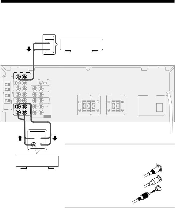
CONNECTING DVD 5.1 CHANNEL COMPONENTS
DVD and LD discs are compatible with both 2 channel and 5.1 channel audio output formats. Refer to page 21 for more information on how to switch between the two input methods. You can connect a DVD player or multi channel decoder equipped with 5.1 analog outputs to the 5.1 analog inputs on the receiver. Always make sure that the receiver is switched off and unplugged from the wall outlet before making or changing any connections.
R L
AM LOOP |
IN |
|
ANTENNA |
||
|
||
|
O |
|
|
U |
|
|
T |
|
|
IN |
|
|
IN |
|
|
IN |
|
FM |
R |
|
UNBAL |
||
75Ω |
E |
|
C |
||
FM |
|
|
ANTENNA |
P |
|
|
L |
|
|
A |
|
|
Y |
CD
|
|
CONTROL |
|
|
OUT |
VCR/ |
|
|
DVR |
|
|
|
IN |
|
TV/ |
IN |
TO |
MONITOR |
||
SAT |
|
TV |
DVD |
IN |
SUB |
/LD |
WOOFER |
|
FRONT |
PREOUT |
|
OUT |
|
SURROUND |
R |
L |
|
CD-R /TAPE /MD
IN |
CENTER |
SUB |
DVD 5.1 CH |
WOOFER |
INPUT |
FRONT |
CENTER |
SPEAKERS |
SPEAKER |
R |
L |
SURROUND |
AC OUTLET |
||
SPEAKERS |
|||
|
|||
R |
L |
|
|
FRONT |
SURROUND |
|
|
|
OUT PUT |
OUT PUT |
SUB |
VIDEO |
COMPONENTS EQUIPPED WITH |
L |
L |
WOOFER CENTER |
OUT |
|
|
|
5.1 CHANNEL ANALOG OUTPUT |
||
|
|
|
|
|
R |
R |
|
|
JACKS |
|
|
|
memo The 5.1 channel input can only be used when  DVD 5.1 CH is selected.
CONNECTING VIDEO COMPONENTS
Connect your video components as shown below. When connecting equipment, make sure the power is switched off and the power cord disconnected from the wall outlet.
VCR, DVR, ETC.
OUT IN
 V
V 
 L
L 
 R
R 
R L
AM LOOP |
IN |
|
ANTENNA |
||
|
||
|
O |
|
|
U |
|
|
T |
|
|
IN |
|
|
IN |
|
|
IN |
|
FM |
R |
|
UNBAL |
||
75Ω |
E |
|
C |
||
FM |
|
|
ANTENNA |
P |
|
|
L |
|
|
A |
|
|
Y |
CD
CONTROL
OUT
VCR/
DVR
IN |
OUT |
TO
SATTV/ IN 
 MONITOR TV
DVD /LD IN
FRONT
SURROUND OUT R 

 L
L 
CD-R /TAPE /MD
IN |
CENTER |
SUB |
DVD 5.1 CH |
WOOFER |
INPUT |
FRONT |
CENTER |
SPEAKERS |
SPEAKER |
R |
L |
OUT
 V
V
L |
DVD/LD PLAYER |
R |
|
IN
VIDEO
SURROUND |
|
SPEAKERS |
|
R |
L |
TV MONITOR
AC OUTLET
10
 Loading...