


USER'S GUIDE
RV-9968
RV-9978
AUDIO/VIDEO RECEIVER
FEDERAL COMMUNICATIONS COMMISSION (FCC) INFORMATION
This device generates and uses radio frequency (RF) energy, and if not installed and used properly, this equipment may cause interference to radio and television reception.
This equipment has been type tested and found to comply with the specifications in Subpart J of Part 15 of FCC Rules. These rules are designed to provide reasonable protection against radio and television interference in a residential installation. However, there is no guarantee that interference will not occur in particular installations.
If this equipment does cause interference to radio or television reception (which you can determine by turning the equipment off and on), try to correct the interference by one or more of the following measures:
•Reorient the receiving antenna (that is, the antenna for the radio or television that is “receiving” the interference).
•Move the unit away from the equipment that is receiving interference.
•Plug the unit into a different wall outlet so that the unit and the equipment receiving interference are on different branch circuits.
If these measures do not eliminate the interference, please consult your dealer or an experienced radio/ television technician for additional suggestions.
Also, the Federal Communications Commission has prepared a helpful booklet, “How To Identify and Resolve Radio TV Interference Problems.” This booklet is available from the U.S. Government Printing Office, Washington, DC 20402. Please specify stock number 004-000-00345-4 when ordering copies.
FOR YOUR SAFETY
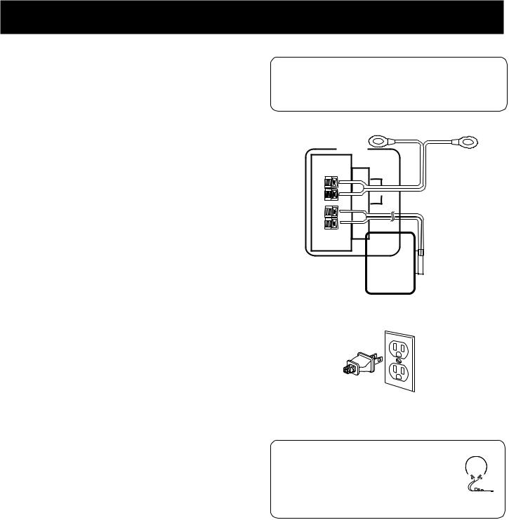
The AC power plug is polarized (one blade is wider than the other) and only fits into AC power outlets one way. If the plug won’t go into the outlet completely, turn the plug over and try to insert it the other way. If it still won’t fit, contact a qualified electrician to change the outlet, or use a different one. Do not attempt to bypass this safety feature.
FOR YOUR RECORDS
In the event that service should be required, you may need both the model number and the serial number. In the space below, record the date and place of purchase, and the serial number:
Model No. RV-9968/RV-9978
Remote Control No. CRK67G
Date of Purchase _____________________________________________
Place of Purchase ________________________________________________
Serial No. ____________________________________________________
SERVICE INFORMATION
This product should be serviced only by those specially trained in appropriate servicing techniques. For instructions on how to obtain service, refer to the warranty included in this Guide.
WARNING: TO PREVENT FIRE OR ELECTRICAL SHOCK HAZARD, DO NOT EXPOSE THIS PRODUCT TO RAIN OR MOISTURE.
|
|
|
|
|
|
|
|
|
|
|
|
|
CAUTION |
|
|
|
|
|
|
|
|
RISK OF ELECTRIC SHOCK |
|
|
|
|
|
|
|
|
DO NOT OPEN |
|
|
|
|
T H E L I G H T N I N G |
CAUTION: TO REDUCE THE |
THE EXCLAMATION |
||||||
FLASH AND ARROW- |
RISK OF ELECTRIC SHOCK, |
POINT WITHIN THE |
||||||
HEAD WITHIN THE |
DO NOT REMOVE COVER |
T R I A N G L E |
I S |
A |
||||
T R I A N G L E |
I S |
A |
( O R B A C K ) . N O U S E R - |
WARNING |
SIGN |
|||
W A R N I N G |
S I G N |
SERVICEABLE PARTS IN - |
ALERTING YOU |
OF |
||||
ALERTING |
YOU |
OF |
S I D E . R E F E R S E RV I C I N G |
I M P O R T A N T |
||||
" D A N G E R O U S |
T O Q U A L I F I E D S E R V I C E |
I N S T R U C T I O N S |
||||||
VOLTAGE" |
INSIDE |
PERSONNEL. |
A C C O M P A N Y I N G |
|||||
THE PRODUCT. |
|
|
|
|
T H E P R O D U C T . |
|||
|
|
|
|
|
|
|
|
|
SEE MARKING ON BOTTOM / BACK OF PRODUCT
2

TABLE OF CONTENTS
FIRST THINGS FIRST ................................................. |
4 |
UNPACK THE RECEIVER .................................................................. |
4 |
BASIC CONNECTIONS...................................................................... |
4 |
CONNECTING, PLACING & BALANCING THE SPEAKERS ........ |
5 |
CONNECTING THE ANTENNAS ................................................... |
7 |
CONNECTING FOR POWER ............................................................ |
7 |
USING HEADPHONES ..................................................................... |
7 |
RECEIVER CONTROLS & OPERATIONS ................... |
8 |
GENERAL CONTROLS ....................................................................... |
8 |
DISPLAY MESSAGES .......................................................................... |
9 |
TUNING THE RECEIVER .................................................................. |
9 |
USING SWAP AUDIO ....................................................................... |
10 |
CONNECTING AUXILIARY COMPONENTS ........... |
11 |
BEFORE YOU CONNECT................................................................... |
11 |
CONNECTING A SATELLITE RECEIVER ........................................ |
12 |
CONNECTING COMPLIMENTARY COMPONENTS .................. |
12 |
CONNECTING A COMPACT DISC ................................................. |
13 |
CONNECTING A TAPE DECK .......................................................... |
13 |
CONNECTING A PASSIVE SUBWOOFER ...................................... |
13 |
THE ULTIMATE CONNECTION ..................................................... |
14 |
USING THE UNIVERSAL REMOTE CONTROL........ |
16 |
BATTERY INSTALLATION ................................................................ |
16 |
BASIC CONTROLS .............................................................................. |
16 |
PROGRAMMING THE UNIVERSAL REMOTE ............................. |
19 |
REMOTE TV CODES ................................................... |
22 |
REMOTE VCR CODES................................................. |
23 |
REMOTE AUDIO & CABLE CODES............................ |
24 |
CARE AND MAINTENANCE .................................... |
25 |
TROUBLESHOOTING TIPS .............................................................. |
25 |
CARE AND CLEANING ..................................................................... |
25 |
EQUIPMENT SPECIFICATIONS....................................................... |
25 |
INDEX ......................................................................... |
26 |
LIMITED WARRANTY............................................... |
27 |
CANADIAN SERVICE ................................................ |
28 |
3
FIRST THINGS FIRST
UNPACK THE RECEIVER
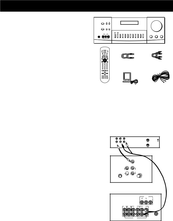
Unpack the receiver and locate all the accessories. You should have:
•one receiver unit;
•one RCA Universal Remote Control (CRK67G);
•two packs - one pair each - of AAA batteries;
•one audio cable (two wires) with red and white RCA connectors;
•one video cable (single wire) with yellow RCA connectors;
•one external, detachable FM T-type antenna;
•one external AM loop antenna;
•one instruction book;
•one owner registration/survey card;
•and one safety leaflet.
VOLUME
POWER |
TUNING |
REMOTE SENSOR |
SPEAKERS |
PRESET SCAN AUTO |
|
MIN |
MAX |
|
|
|
|
|
CENTER |
TEST |
|
|
|
|
|
|
|
|
|
|
|
VIDEO |
PRO LOGIC 3 STEREO |
HALL |
MODE |
TONE |
BYPASS |
FM/AM |
CD |
TAPE |
VCR |
VIDEO |
TV |
|
|
PHONES |
IN |
L |
R |
|
|
|
|
|
|
|
|
|
BALANCE |
BASS |
TREBLE |
central unit
|
|
SA |
T• |
|
|
|
|
POWER |
VCR |
CABLE TV |
|
|
|||
LD¥VC R2 |
DVD |
|
|
|
|||
AM•FM |
|
TAPE |
|
CD |
|
|
|
REV PLAY |
|
FWD |
|
|
|||
REC |
|
STOP |
|
PAUSE |
|
|
|
GUIDE•RDM |
|
H |
|
|
SKIP |
|
|
|
C + |
|
|
|
|
||
LO |
|
|
|
|
ENTER |
|
|
|
|
|
|
VO |
|
|
|
V |
|
|
|
|
L |
|
|
MUTE |
|
CH- |
|
|
GO BACK¥DISC |
video cable |
audio cable |
4 |
5 |
|
|
6 |
|
||
1 |
2 |
|
|
3 |
|
|
|
7 |
8 |
|
|
9 |
|
|
|
INPUT•SEEK |
|
|
ANTENNA |
|
|
||
|
0 |
|
|
|
|
|
|
INFO |
CLEARRESET•REPDELAY |
|
|
||||
|
|
|
|
|
CH CTRL |
|
|
MENU |
|
|
|
|
TV MENU |
|
|
|
MOVE |
|
|
|
|
||
SELECT |
|
|
|
|
|
|
|
PIP |
– |
|
+ |
SWAP PIP |
|
|
|
PLAYLIST |
|
• |
CTR MODE |
|
|
||
|
|
REAR |
|
S |
|
|
|
|
|
|
|
CTR |
|
|
|
|
|
|
|
|
R D |
|
|
|
|
|
|
|
U |
|
|
BY-PASS SWAP LEVEL ROUN |
|
|
|||||
|
AUDIO |
|
|
|
|
|
|
remote |
AM loop |
FM T-type antenna |
|||||
|
|||||||
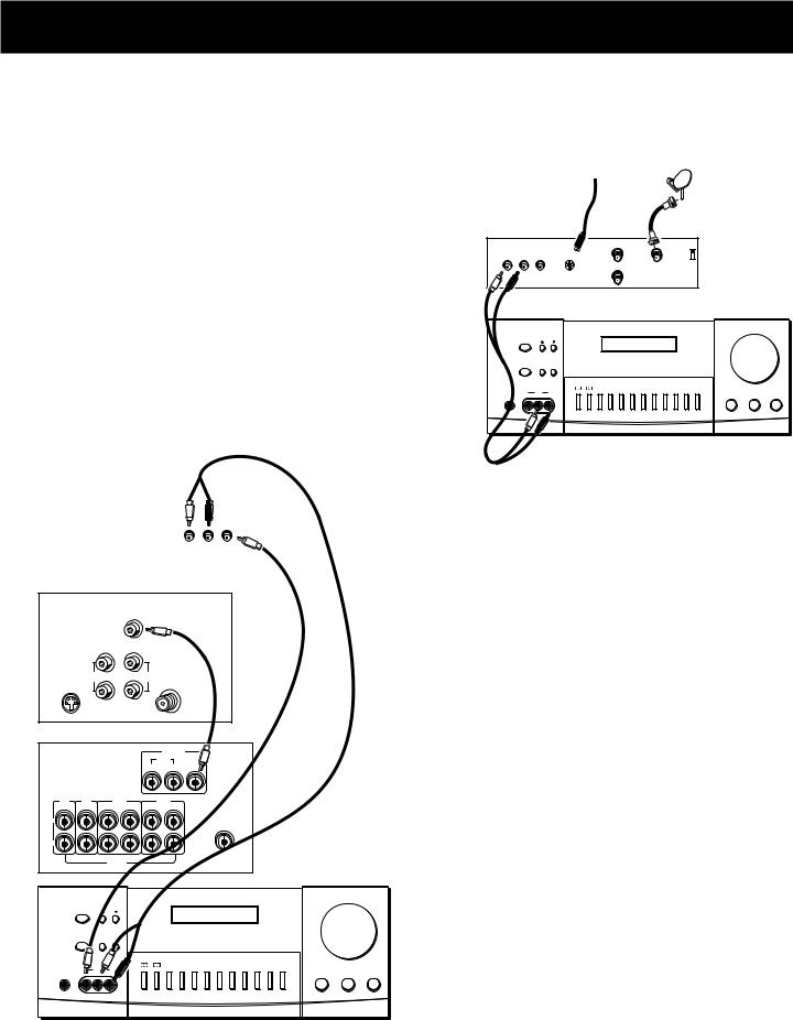
BASIC CONNECTIONS
Assuming you have a VCR, the following steps will help you quickly set up your new receiver. If you have more electronic components, consult the table of contents or index for the page on which to find the connection description that best suits your situation.
*The wires and jacks have been color-coded to assist you.
1.Using an audio wire with red and white connectors, connect the audio “OUT” jack on the back of your stereo VCR to the audio “IN” jack under the VCR heading on the back of the receiver.
2.Using the video cable with yellow connectors, connect the video “OUT” jack on the back of your VCR to the “VIDEO IN” or “VIDEO INPUT” on the back of your TV. If there are multiple video jacks on the back of your TV, use “VIDEO 1.”
NOTE: If your TV has more than one video input, make sure the VCR and VIDEO buttons tune the TV to the same channel that the receiver monitor out is plugged into. Refer to the TV’s user’s guide for more information.
VCR |
IN |
IN FROM ANT |
|
CH3 |
|
|
OUT |
CH4 |
|
OUT TO TV |
|
|
VIDEO R L |
|
|
|
TV
S-VIDEO 

AUDIO
RECEIVER
L
R
AUDIO
4
FIRST THINGS FIRST
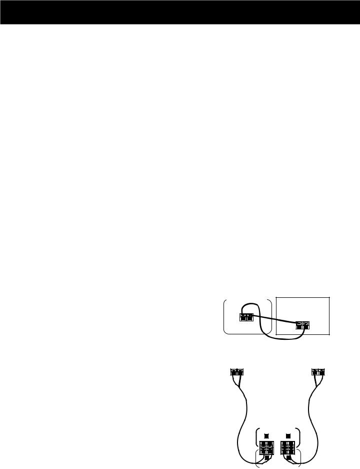
CONNECTING, PLACING & BALANCING THE SPEAKERS
CONNECTING THE WIRES
Each speaker - the two main, two surround and one central - has a designated set of terminals on the back panel of the central unit.
Uncoil the speaker wires and locate the bare ends. Press and hold down on the tab to open the red terminal, then insert the red (+) wire. Release hold to close tab. Use the same procedure for black (-) wire into black terminal.
WARNING: Be sure to follow these instructions carefully. The system can be damaged if speakers are improperly connected.
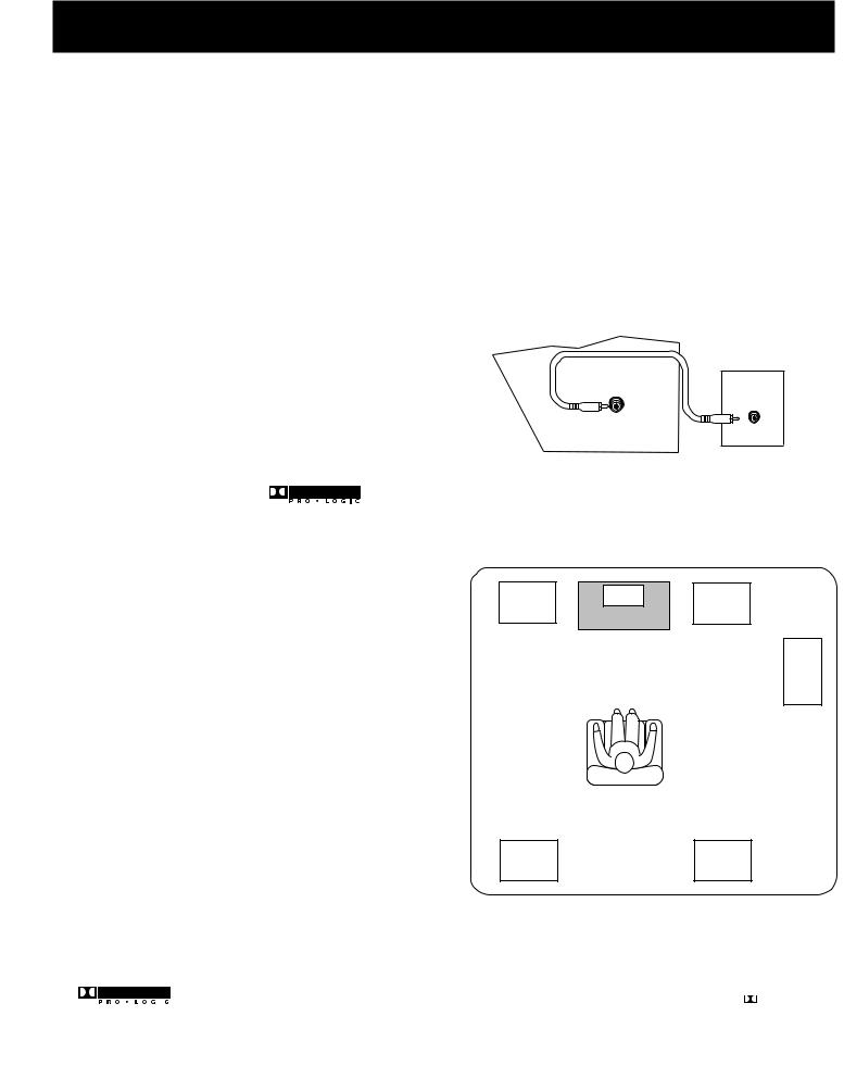
SETTING UP FOR SURROUND SOUND
THE MAIN SPEAKERS
The two main speakers should be set between six and 10 feet apart. Putting the speakers any closer or any farther apart may result in distorted sound.
The speakers should also form a 45 degree angle to the central listening point in the room, creating a triangle of listening enjoyment.
NOTE: You may need to place the main speakers closer together when not utilizing the center speaker. Do not place them so close, however, that their
magnetic fields affect the TV’s reception.
THE CENTER SPEAKER
For optimal performance, you should try to place the center speaker as close as possible to the same height as the left and right main speakers. You should also try to align all three speakers, or set the center speaker slightly behind the left and right mains. However, you should never place the center speaker forward of the left and right mains, as this will distort the sound for those listeners not seated in the center of the room.
THE SURROUND SPEAKERS
Placement of the surround speakers for optimal performance is truly subject to the size and type of room in which the system is to be placed.
The following are a few position suggestions.
1.Set the speakers on the side walls, facing each other, approximately two to three feet above the listeners head.
CENTER SPEAKER (8Ω )
CENTER CHANNEL
SURROUND SOUND |
|
SURROUND SOUND |
||||||||||||
SPEAKER |
|
SPEAKER |
||||||||||||
|
|
|
|
|
|
|
|
|
|
|
|
|
|
|
|
|
|
|
|
|
|
|
|
|
|
|
|
|
|
AUDIO |
MAIN SPEAKERS |
||
|
(8Ω ) |
||
RECEIVER |
|
||
R |
L |
||
|
|||
|
R |
L |
|
REAR SPEAKERS (16 Ω )
5
FIRST THINGS FIRST
2. Aim the speakers directly at the two main speakers, matching height to height. If the room is sparsely decorated, it may be necessary to slightly tilt the speakers down to increase sound
quality. If the room is densely decorated, it may be necessary to face the speakers toward the rear wall or at the ceiling.
3. Mount the speakers up on the ceiling. Set them a few feet wide of the listeners and make sure they are facing one another, not the floor.
Obviously there are many more possible positions, so it may be necessary to simply experiment to find the right balance for your situation.
SUBWOOFER
SUBWOOFER
Before you begin, make sure that the subwoofer is turned off and unplugged.
Connect your A/V receiver to the subwoofer as shown.
NOTE: A receiver with a single output should be |
LOW-LEVEL |
INPUT |
|
connected to the input labeled LOW-LEVEL INPUT. |
|
RECEIVER
SUBWOOFER
OUT
BALANCING YOUR SPEAKERS
Your system is equipped with *, which
enables you to reproduce sound effects as they were intended. But to do so, the speakers must be correctly balanced.
To balance the speakers using the Test Tone, all speakers must be connected to your receiver. Your receiver must be in the Dolby Pro Logic Surround Mode.
1.Press the TEST TONE button on the receiver front panel. The receiver generates a “pink noise” and applies it automatically at two-second intervals to the left main channel, center channel, right main channel and left and right rear channels (simultaneously), in that order.
2.As the pink noise is generated, go to the spot in the room where you are most likely to be when listening to your system. The rear surround and center speakers should be adjusted to equal the level of output from the left and right main speakers.
3.Make adjustments by pressing the REAR•CTR button, and then the +/- button on your remote control. The output from the selected speaker(s) is adjusted accordingly.
A SAMPLE SET UP FOR SURROUND SOUND ENJOYMENT
Main |
Center |
Main |
Left |
TV |
Right |
|
|
.Opt
Subwoofer
Rear |
Rear |
Left |
Right |
* |
|
Manufactured under license from Dolby Laboratories Licensing Corporation. Dolby, the double-D symbol ( ) and |
|
||
|
“ Pro Logic” are trademarks of Dolby Laboratories Licensing Corporation. |
|
6
FIRST THINGS FIRST
Each time you press the + or - button on your remote control to adjust a channel, the receiver provides you with two more seconds of pink noise to that channel before moving on to the next.
4.Press the TEST TONE button again to end the test.
You may not need to check or adjust these levels again unless you move your system, rearrange the speakers, or change your preferred seating location in the room.
CONNECTING THE
ANTENNAS
The AM and FM antennas connect to the AM and FM terminals on the system’s back panel. They must be hooked up for you to receive clear reception.
Uncoil the antenna wires and locate the bare ends. Press down on the tab to open the terminal and insert the wire. Snap the tab closed.
After connecting the antennas, extend them to their full length and adjust their positioning for better reception.
CONNECTING FOR POWER
Make sure you connect all your other electronic components and your speakers before plugging your receiver into the outlet.
Plug the power cord in the wall outlet, matching the wide blade of the plug with the wide slot in the outlet. Be sure to insert the plug completely.
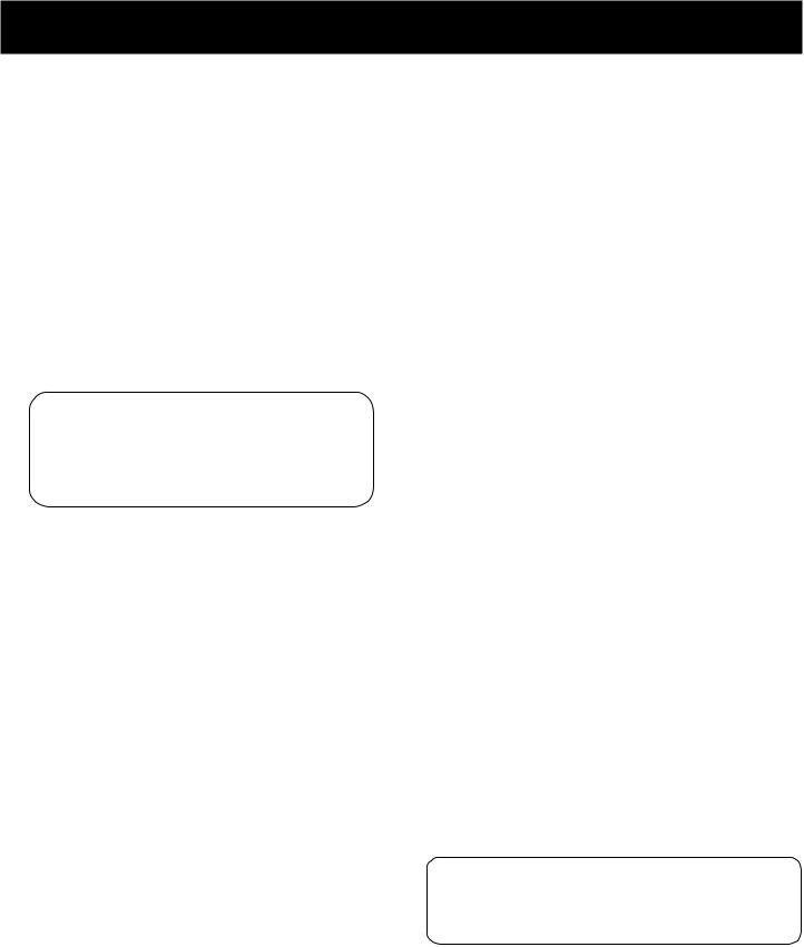
USING HEADPHONES
To listen privately through your audio system, use the PHONES jack to the right of the volume dial on the receiver.
NOTE: Headphones are not included.
Sit Back and Listen ...
Fine tuning is best performed with the remote control so that adjustments can be made from the viewing or listening area.
ANTENNA
FM 
AM
LOOP
Have a blast - Just not in your ears!
Make sure you turn down the volume before you put on the headphones. Increase the volume to the desired level after headphones are in place.
7
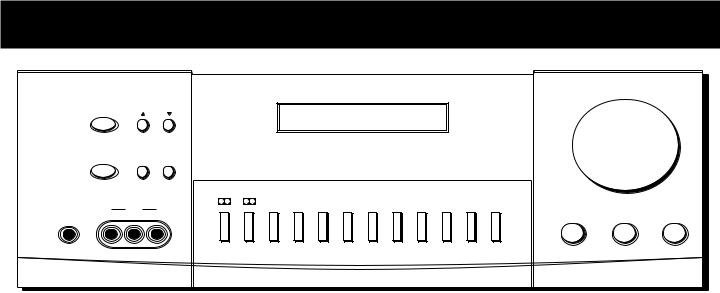
RECEIVER CONTROLS & OPERATIONS
|
POWER |
|
TUNING |
REMOTE SENSOR |
|
|
|
|
|
|
|
|
SPEAKERS |
PRESET SCAN AUTO |
|
|
|
|
|
|
|
|
|
|
|
|
|
|
|
CENTER |
TEST |
|
|
|
|
|
|
VIDEO |
|
PRO LOGIC 3 STEREO |
HALL |
MODE |
TONE |
BYPASS |
FM/AM |
CD |
TAPE |
|
|
|
|
|
|
|
|
|
|
|
|
PHONES |
IN |
L |
R |
|
|
|
|
|
|
|
|
VOLUME
MIN |
MAX |
VCR |
VIDEO |
TV |
|
|
|
|
BALANCE |
BASS |
TREBLE |
GENERAL CONTROLS
POWER STAND BY/ON
The POWER STANDBY/ON button activates or deactivates the system. When the system is activated, the unit will default to the last mode it was in before power was removed.
TUNING DOWN/UP
The TUNING DOWN/UP buttons allow you to scan the active frequency for the radio station of your choice.
SPEAKERS
The SPEAKERS button allows to activate/deactivate your speakers, giving you more control over the customizing of your listening.
PRESET SCAN
The PRESET SCAN button allows you easy access for up to 30 preset radio stations.
AUTO
The AUTO button allows you to select auto or manual tuning.
BALANCE
The BALANCE dial allows you to manually adjust the balance of sound coming from your speakers.
BASS
The BASS dial allows you to manually adjust the amount of bass the unit emits.
TREBLE
The TREBLE dial allows you to manually adjust the amount of treble the unit emits.
FUNCTION BUTTONS
The function buttons include CD, TAPE, FM/AM, TV, VCR, VIDEO.
TEST TONE
The TEST TONE button can only be used in the Dolby Pro Logic mode. This feature allows you to balance your speakers as they emit a sound, called a “pink noise,” in the left, center, right and surround channels sequentially for two seconds each.
NOTE: This process is explained more in-depth in “Balancing Your Speakers,” page 4.
CENTER MODE
The CENTER MODE button allows you to select the Normal, Phantom or Wide mode. These modes are only available when Dolby Pro Logic or Dolby 3 Stereo are activate.
NORMAL
The Normal mode can be activated in both Pro Logic and 3 Stereo. This mode takes the low bass frequencies from the center channel and distributes them to the left and right main speakers to maintain the program’s original integrity.
PHANTOM
The Phantom mode can only be reached while the Pro Logic mode is active. It uses the two main speakers and the two surround speakers. The center speaker is off and the sound that usually comes from it is distributed through the left
and right main speakers.
8
RECEIVER CONTROLS & OPERATIONS
WIDE
The WIDE mode can be activated in both the Pro Logic and the 3 Stereo modes. This mode utilizes just the three front speakers - left main, right main and center - with all audio delivered through the center speaker. The center speaker
will reproduce the same bass levels as the left and right main speakers.
SURROUND MODE
Included in the SURROUND MODE category are Dolby Pro Logic, Dolby 3 Stereo, Hall and Bypass.
DOLBY PRO LOGIC
The Pro Logic mode uses all five speakers so the sound envelopes the room.
DOLBY 3 STEREO
The 3 Stereo mode uses the two main and one center speaker.
HALL
The Hall mode recreates the effect of listening to a concert or watching a play from inside a music hall. It utilizes the main and surround speakers.
BYPASS
The Bypass mode utilizes just the main speakers.
MASTER VOLUME
The Master Volume dial allows you to adjust the level of audio output.
PHONES
The receiver has been equipped with a Phones jack. Plug your headphones - not included - into the jack and listen to your favorite media in private.
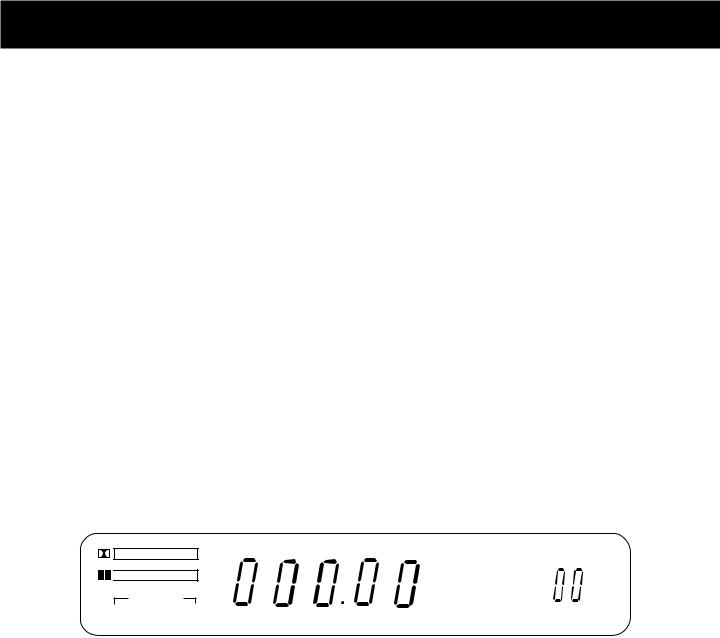
DISPLAY MESSAGES
The following is an example of all the display messages you may encounter while using your receiver. Specific messages are referenced within the section(s) they apply.
DOLBY SURROUND
P R O • L O G I C

 DOLBY 3 STEREO
CENTER MODE
NORMAL WIDE PHANTOM
HALL
TUNED STEREO |
MUTE MEMORY |
AUTO |
PRESET |
|
|
|
|
|
|
DELAY |
mS |
FM |
|
TIME |
|
AM |
MHz |
REAR |
dB |
|
kHz |
CENTER |
ch |
|
|
|
|
BYPASS |
|
|
SPEAKERS OFF |
TUNING THE RECEIVER
1.Push the FM/AM button on the receiver (or the AM•FM button on the remote) to activate the tuner.
2.Press the FM/AM button on the receiver (or the AM•FM button on the remote) again to select the FM or AM band.
TUNING
Press the FF on your remote button to move up the AM or FM band.
Press the REW button on your remote to move down the AM or FM band.
AUTO TUNING
Use the AUTO feature to automatically search for stations of sufficient strength.
Press AUTO on your receiver (or the INPUT•SEEK button on your remote) to put the receiver into AUTO mode. “AUTO” appears in the display. Press TUNING up or down button on the receiver to search. The tuner finds and stops on the next station whose frequency is strong enough to be received. To continue the search, press TUNING up or down button again.
STORING STATIONS IN MEMORY
You can store up to 30 AM and FM stations. These stations can be stored in random order.
9
RECEIVER CONTROLS & OPERATIONS
TO STORE A STATION
1.Press the FM/AM button on the receiver (or the AM•FM button on the remote) to turn on the receiver.
2.Select the band—FM or AM.
3.Select the station you want to store in memory using the methods described above.
4.Press the MENU-SELECT button on the remote. “MEMORY” blinks in the display. While “MEMORY” is blinking, press number buttons on the remote for the station.
For stations 1, 2 or 3 press 0, then press 1, 2, or 3. For stations 4 through 30, press the numbers directly.
If the Memory indicator on the display turns off before you preset your station selection, press MENU-SELECT again.
If the receiver is disconnected from its power source, the preset stations are maintained in memory for up to 7 days.
TO PLAY A PRESET STATION
Press the appropriate Preset Stations number. For stations 1, 2 or 3 press 0, then press 1, 2, or 3. For stations 4 through 30, press the numbers directly.
TO USE SWAP AUDIO
When you are watching TV and turn on PIP, you can turn on another video source and swap the sound from the large picture coming from the TV to the small picture coming from the other video source.
1.Press TV on the remote to turn on the TV and put the receiver in TV mode.
2.Press the PIP button. The empty PIP appears on the screen.
3.Activate a video source for the PIP. The picture from the video source appears in the PIP.
4.Press TV.
5.Change to the TV channel you want to watch on the
large screen.
6.Press SWAP AUDIO to swap the sound between the large picture and the small picture.
7.To swap the video between the large picture and the small picture, use the SWAP PIP button on the remote.
If you swap the TV picture to the PIP and the other video source to the large picture, you may not be able to swap
the audio.
Or, press CH + on your remote to tune to the next preset station or CH - to tune to the previous preset station.
PRESET SCANNING
Use the PRESET SCAN button on the receiver’s front panel to review the preset stations stored in the tuner’s memory. “PRESET” and the station’s location in memory appear in the display. The tuner automatically scans all preset stations in order, pausing at each one for approximately 5 seconds.
When the tuner reaches the station you want, press PRESET SCAN to stop the scanning. If the scan is not interrupted, the tuner reviews all preset stations in order, stopping at the point where the scan began.
USING SWAP AUDIO
Swap audio lets you change the sound from the large picture to the small picture when you are watching TV and using picture-in-picture (PIP) with an external video source.
TO CHANGE THE VIDEO SOURCE AND SWAP THE AUDIO
If you want to change the video source for the PIP and want to be able to use SWAP AUDIO:
1.Turn off PIP.
2.Change the video source to another video component connected to the receiver.
3.Press TV to watch the TV.
4.Press PIP. The video source appears in the PIP. The video from the TV appears in the large picture.
5.Press SWAP AUDIO to swap the audio as you want.
The Swap Audio feature may not work with all TV brands with the PIP feature.
If your TV has a PIP feature, see the TV’s user’s guide for instructions for using it.
10
CONNECTING AUXILIARY COMPONENTS
|
ANTENNA |
|
|
|
|
|
|
|
FM |
|
|
|
|
|
|
|
|
|
VIDEO |
|
|
|
|
|
|
VCR |
MONITOR |
|
|
|
|
IN |
OUT |
OUT |
|
|
AM |
|
|
|
|
|
|
LOOP |
|
|
|
|
TV |
CD |
TAPE |
|
|
VCR |
|
IN |
IN |
IN |
OUT |
IN |
OUT |
|
L
R
AUDIO
|
MAINSPEAKERS (8Ω) |
|
|||
+ |
R |
- |
- |
L |
+ |
SUB |
|
|
|
|
|
WOOFER |
|
|
|
|
|
+ |
R |
- |
- |
L |
+ |
|
REAR SPEAKERS (16 |
Ω) |
|
||
AC-120V 60Hz
CENTER
SPEAKER(8 Ω)
-+
BEFORE YOU CONNECT...
•Protect components from power surges.
•Connect all components before plugging any power cords into the wall outlet.
•Always turn off the receiver and/or components before you connect or disconnect any cables.
•Always make sure the color-coded plugs match the color of the terminals in which they are inserted. The connection cable plugs and jacks are colorcoded as follows:
Speaker Terminals Red for positive (+) terminals. Black for negative (-) terminals.
RCA Phono Type Terminals Red for the right (R) channel. White for the left (L) channel.
Yellow for the video (V). Black for the subwoofer. (Not Included)
•Some units may be supplied with connection plugs that are color coded red and black
instead of red and white. In this case, the black plug takes the place of the white plug.
•Contact Consumer Relations if you have questions concerning the connections or components.
POSITION CABLES CORRECTLY TO AVOID AUDIO HUM OR INTERFERENCE
•Insert all cable plugs firmly into their jacks.
•Place audio/video cables to the sides of the receiver’s back panel instead of straight down the middle after you connect the components.
•Try not to coil any power cables and keep them away from the audio/video cables as
much as possible.
•Make sure all antennas and cables are properly grounded. Refer to the Safety Tips sheet packed with your receiver.
PROTECT YOUR COMPONENTS FROM OVERHEATING
•Do not block ventilation holes in any component. Arrange the components so that air can
circulate freely.
•Do not stack components directly on top of each other.
•Allow adequate ventilation when placing your components in a stand.
•Place an amplifier near the top shelf of the stand so heating air rising from it will not
flow around other components. If you have a satellite receiver, you should place it on
the top shelf.
11
CONNECTING AUXILIARY COMPONENTS
CONNECTING A SATELLITE RECEIVER
Using a paired (red/white) stereo cable, a single (yellow) video cable and two coaxial cables, connect your new audio receiver to your satellite receiver as shown to the right.
To watch TV programs in stereo after connection, press TV and tune to the desired channel. To watch satellite programming, press SAT•CABLE and tune to the desired channel.
NOTE: Do not stack electronic components or other objects on top of the satellite receiver. The slots on top of the receiver must be left uncovered to allow proper airflow to the unit. Blocking the airflow to the unit could impair performance or damage your receiver and other components. Also, do not stack the satellite receiver on top of a “hot component,” such as an audio power amplifier.
COMPLIMENTARY
COMPONENT
L R VIDEO
AUDIO
TV |
|
|
VIDEO |
|
|
|
|
|
|
|
|
|
|
||
|
|
|
INPUT |
|
|
|
|
|
|
|
RIGHT |
|
|
|
|
|
OUT |
|
AUDIO |
IN |
|
|
|
S-VIDEO |
|
|
|
|
|
|
|
|
|
|
L / |
|
|
CABLE / |
|
|
|
|
MONO |
|
|
ANTENNA |
|
|
|
|
|
VIDEO |
|
|
|
|
|
|
|
VCR |
|
MONITOR |
|
|
|
|
|
IN |
OUT |
OUT |
|
TV |
CD |
|
TAPE |
VCR |
|
|
|
IN |
IN |
IN |
OUT |
IN |
OUT |
|
|
L |
|
|
|
|
|
SUB |
|
|
|
|
|
|
|
WOOFER |
|
R |
|
|
|
|
|
|
|
|
|
AUDIO |
|
|
|
|
|
|
|
|
|
|
|
|
VOLUME |
|
POWER |
TUNING |
REMOTE SENSOR |
|
|
|
|
|
SPEAKERS PRESET SCAN AUTO |
|
|
|
|
||
|
|
|
|
|
|
MIN |
MAX |
|
|
|
|
|
CENTER |
TEST |
|
|
|
|
|
|
|
|
|
|
|
VIDEO |
PRO LOGIC 3 STEREO |
HALL |
MODE |
TONE |
BYPASS |
FM/AM |
CD |
TAPE |
VCR |
VIDEO |
TV |
|
|
|
|
|
|
|
|
|
|
|
|
|
|
|
|
|
|
PHONES |
IN |
L |
R |
|
|
|
|
|
|
|
|
|
BALANCE |
BASS |
TREBLE |
SATELLITE DISH
TO TV S-VIDEO
RCA DSS |
|
|
|
IN FROM ANT |
|
RECEIVER |
|
|
S-VIDEO |
CH3 |
|
|
|
CH4 |
|
||
|
|
|
|
OUT TO TV SATELLITE |
|
L |
R |
VIDEO |
|
IN |
|
|
|
|
|||
|
AUDIO |
|
|
|
|
AUDIO |
|
|
|
|
VOLUME |
RECEIVER |
POWER |
TUNING |
REMOTE SENSOR |
|
|
|
|
|
|
|
|
|
SPEAKERS |
PRESET SCAN AUTO |
|
|
|
|
|
|
|
MIN |
MAX |
|
|
|
|
CENTER TEST |
|
|
|
VIDEO |
PRO LOGIC 3 STEREO HALL MODE TONE BYPASS FM/AM CD TAPE VCR VIDEO TV |
|
|
PHONES |
IN |
L R |
|
BALANCE |
BASS TREBLE |
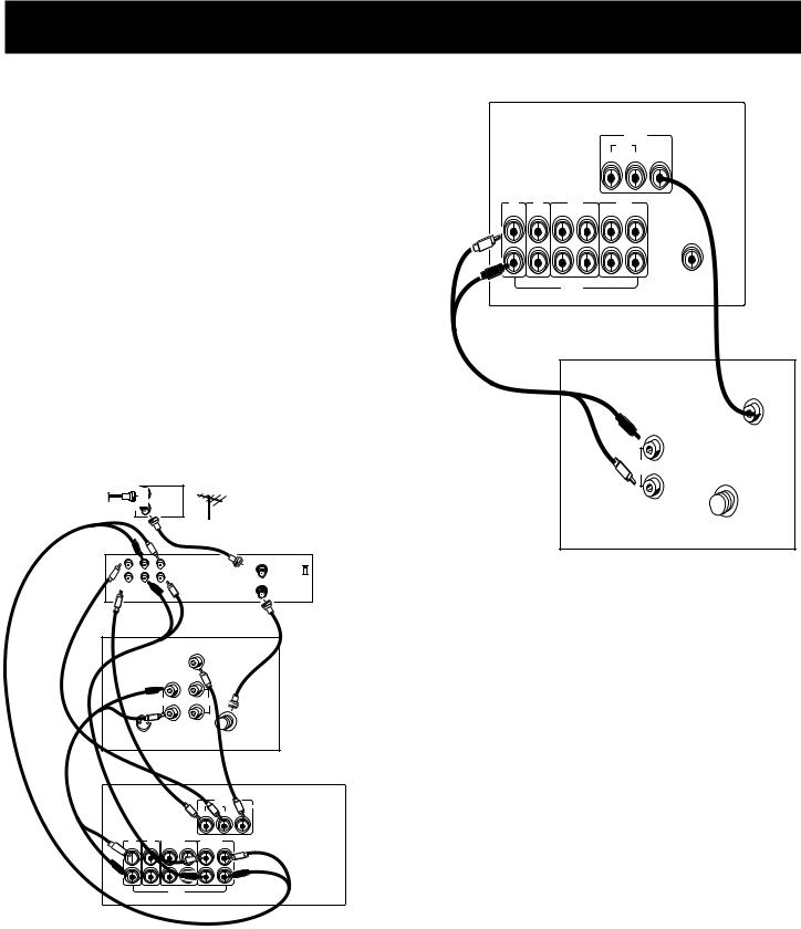
CONNECTING COMPLIMENTARY COMPONENTS
You can connect a laserdisc player, second VCR or camcorder/video recorder to the VIDEO connection.
Using a paired (red/white) stereo cable and two single (yellow) video cables, connect your new audio receiver to the complimentary component as shown to the right.
To play laserdiscs or videos, press the LD•VCR2 and then play.
NOTES: When using this connection for a second VCR, the recording option is not available.
If your camcorder or video camera does not have an RCA-type terminal for audio/video, you can purchase an adapter from an RCA dealer or electronic parts store.
If the video connection is being used when you try to hook up your video recorder or camcorder, connect the component through any other available video output.
12
CONNECTING AUXILIARY COMPONENTS
CONNECTING A COMPACT DISC PLAYER
Using one paired (red/white) stereo cable, connect your new receiver to your compact disc player as shown to the right.
To play a CD, press CD, put the receiver in CD mode and press PLAY.
NOTE: The AUDIO SOURCE connection can be used as input for any stereo audio signal.
TAPE |
IN |
OUT |
DECK |
|
|
|
L |
L |
|
R |
R |
AUDIO |
|
|
VIDEO |
|
RECEIVER |
|
|
|
|
|
|
VCR |
MONITOR |
|
|
|
IN |
OUT |
OUT |
TV |
CD |
TAPE |
VCR |
|
IN |
IN |
IN OUT IN |
OUT |
|
L |
|
|
|
SUB |
|
|
|
|
WOOFER |
R |
|
|
|
|
|
|
AUDIO |
|
|
CD
PLAYER
L R
AUDIO
RECEIVER
|
|
|
|
VIDEO |
|
|
|
|
|
VCR |
MONITOR |
|
|
|
IN |
OUT |
OUT |
CD |
TAPE |
|
|
VCR |
|
IN |
IN |
OUT |
IN |
OUT |
|
L |
|
|
|
|
SUB |
|
|
|
|
|
WOOFER |
R |
|
|
|
|
|
|
AUDIO |
|
|
|
|
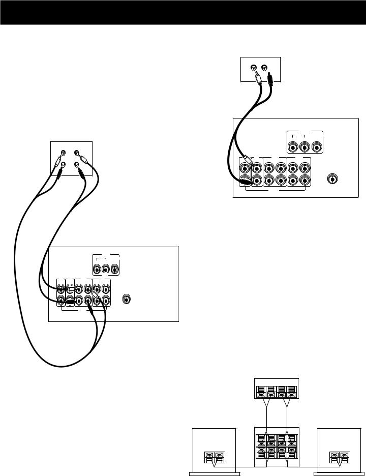
CONNECTING A TAPE DECK
Using two paired (red/white) stereo cables, connect your new receiver to your tape deck as shown in the diagram to the right.
To play a tape, press TAPE and then PLAY. To record a tape, turn on the audio source you want to record from and then press RECORD on the tape player.
CONNECTING A PASSIVE SUBWOOFER
Should you choose to use a passive subwoofer, the hook up is slightly different from that of a powered one.
If necessary, remove the vinyl covering from the ends of the wires and twist the wire. Press down and hold the tab on the back of the speaker. Insert the wire in the hole, matching (+) to (+) and (-) to (-). Release the tab and pull the wire gently to make sure it is securely connected
Speaker |
|
+ |
_ |
|
|
A/V Receiver |
|
or Television |
|
+ R _ |
+ L _ |
+ R _ |
+ L _ |
+ R _ |
+ L _ |
Subwoofer |
|
Speaker |
|
+ |
_ |
|
|
13
CONNECTING AUXILIARY COMPONENTS
THE ULTIMATE CONNECTION
Should you choose to utilize your new receiver to its fullest potential by running all your audio components through it, you will need purchase additional connectors. How many and what kind is purely situational.
The following is a complete description of all the jacks on the back of the receiver and how they can be utilized to provide greater enjoyment. Remember when connecting audio and video cables that, in addition to being color-coded for connection accuracy, RIGHT jacks always connect to RIGHT jacks and LEFT to LEFT, but IN jacks connect to OUT jacks and OUT jacks connect to IN.
NOTE: Please be advised the jacks are given generalized names and locations. Your TV/VCR/cable box/satellite receiver/ etc. might have a different configuration of jacks with different names. The diagrams below are outlined in the simplest possible detail.
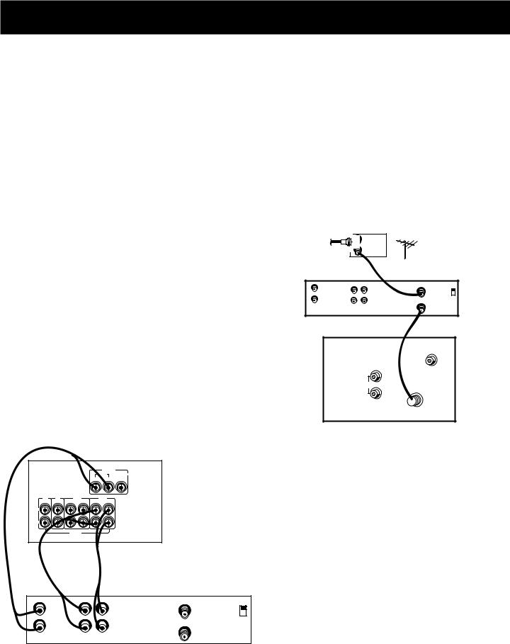
STEP 1: CONNECTING YOUR
SATELLITE/CABLE RECEIVER
Connect the “OUT” jack on your cable/satellite receiver box to the “IN FROM ANTENNA” jack on the back of your VCR.
Then connect the “OUT to TV” jack on the back of your VCR to the “CABLE/ANTENNA” jack on the back of your TV.
CABLE |
IN |
|
|
|
BOX |
|
|
|
OUT |
|
|
|
|
ANTENNA |
|
|
|
OR |
|
VCR |
IN |
|
IN FROM ANT |
L |
CH3 |
||
|
OUT |
R |
CH4 |
|
OUT TO TV |
||
|
VIDEO |
IN OUT |
|
|
TV |
|
VIDEO |
|
|
|
INPUT |
|
|
R |
|
|
|
OUT AUDIO |
|
|
|
L |
CABLE / |
|
|
ANTENNA |
|
|
|
|
|
|
|
|
|
|
AUDO |
|
|
|
VCR |
MONITOR |
RECEIVER |
|
|
|
VIDEO |
|
|
|
|
IN |
OUT |
OUT |
|
TV |
CD |
TAPE |
VCR |
|
|
IN |
IN |
IN OUT IN |
OUT |
|
|
L |
|
|
|
|
|
R |
|
|
|
|
|
|
|
AUDIO |
|
|
|
VCR
|
|
|
IN FROM ANT |
IN |
|
L |
CH3 |
|
|
|
|
|
|
|
CH4 |
OUT |
|
R |
OUT TO TV |
|
|
||
VIDEO |
OUT |
IN |
|
STEP 2: CONNECTING
YOUR VCR TO THE RECEIVER
Using video cables, connect the video VCR “IN” and “OUT” jacks on the back of your receiver to the “OUT” and “IN” video jacks on the back of your VCR.
Using audio cables, connect the right and left “IN” and “OUT” audio VCR jacks on the back of your receiver to the right and left “IN” and “OUT” jacks on the back of your VCR.
14
CONNECTING AUXILIARY COMPONENTS
STEP 3: CONNECTING YOUR RECEIVER TO YOUR TV
Using audio cables, connect the left and right “OUT” audio jacks on the back of your TV to the TV audio jacks on the back of your receiver.
AUDIO
RECEIVER
|
|
|
|
|
VIDEO |
|
|
|
|
|
|
VCR |
MONITOR |
|
|
|
|
IN |
OUT |
OUT |
TV |
CD |
|
TAPE |
|
VCR |
|
IN |
IN |
IN |
OUT |
IN |
OUT |
|
L |
|
|
|
|
|
SUB |
WOOFER
R
AUDIO
CABLE |
|
IN |
|
|
|
|
|
BOX |
|
|
|
|
|
|
|
|
OUT |
|
|
|
|
|
|
|
|
|
OR |
ANTENNA |
|
||
|
|
|
|
|
|||
|
|
IN |
|
|
IN FROM ANT |
VCR |
|
|
|
|
|
CH3 |
|||
|
|
OUT |
|
|
CH4 |
|
|
|
|
|
|
OUT TO TV |
|
||
VIDEO |
R |
L |
|
|
|
|
|
|
|
|
|
|
|||
|
|
|
VIDEO |
|
TV |
|
|
|
|
|
INPUT |
|
|
|
|
|
|
|
RIGHT |
|
|
|
|
|
|
OUT |
AUDIO |
IN |
|
|
|
S-VIDEO |
|
|
|
|
|
||
|
|
|
L / |
|
|
CABLE / |
|
|
|
|
|
|
ANTENNA |
|
|
|
|
|
MONO |
|
|
|
|
|
|
|
|
|
|
|
|
|
|
|
|
|
|
|
AUDO |
|
|
|
|
|
VIDEO |
|
RECEIVER |
|
|
|
|
|
VCR |
MONITOR |
|
|
|
|
|
IN |
OUT |
OUT |
|
TV |
CD |
|
TAPE |
|
VCR |
|
|
IN |
IN |
IN |
OUT |
IN |
OUT |
|
|
L 
R
AUDIO
TV
|
|
VIDEO |
|
|
INPUT |
|
R |
|
OUT |
AUDIO |
|
|
|
|
|
L |
CABLE / |
|
ANTENNA |
WHEN YOU’RE ALL CONNECTED....
When you’re all finished connecting your basic components together, you’ll have quite a mess of wires back there.
Add to this a tape deck, laserdisc player and second VCR and you can imagine the confusion. Just be patient and follow each component’s user’s guide and you’ll be rewarded with excellent audio and hours of top quality entertainment.
15
USING THE UNIVERSAL REMOTE CONTROL
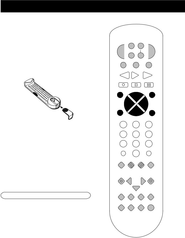
BATTERY INSTALLATION
The remote control operates on four batteries, included with your system. Install them before attempting to operate the remote.
1.Slide the battery compartment cover off the back of the remote.
2.Insert 4 AAA batteries, matching the + and - ends of each battery with the symbols in the compartment.
3.Replace the cover.
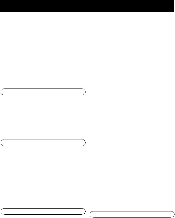
BASIC CONTROLS
Your remote control is capable of operating most RCA audio and video equipment. To use the remote control effectively, always aim it directly at your receiver.
POWER Turns the AM/FM receiver off with two presses. If you have multiple components turned on and not the AM/FM receiver, pressing POWER once turns off the last component turned on. Pressing POWER again quickly turns off all other components.
VOL UP and DOWN Increases or decreases the volume.
MUTE Turns off the receiver’s sound. Press again to restore the sound.
RECEIVER CONTROLS
AM•FM Activates the tuner and toggles between the AM band and the FM band.
CTR MODE Changes the Center mode when using Dolby Pro Logic Surround or Dolby 3 Stereo surround modes. Press once and the current mode appears. Press again to change the mode.
WER |
VCR |
T• |
TV |
|
SA |
CABLE |
|||
PO |
R2 |
D |
|
|
|
||||
|
|
|||
|
LD¥VC |
|
VD |
|
|
|
|
|
|
AM•FM TAPE CD
REV PLAY FWD
REC |
STOP |
PAUSE |
GUIDE•RDM |
H |
SKIP |
C + |
||
L |
|
ENTER |
|
V |
|
O |
|
|
|
O |
|
V |
|
L |
MUTE |
CH- |
GO BACK¥DISC |
1 |
2 |
3 |
4 |
5 |
6 |
7 8 9
INPUT•SEEK ANTENNA
0
INFO CLEARRESET•REPDELAY
CH CTRL MENU  TV MENU
MOVE |
|
|
|
|
|
SELECT |
|
|
|
|
|
PIP – |
+ |
SWAP PIP |
|||
PLAYLIST |
• |
CTR MODE |
|||
|
REAR |
|
|
|
|
|
CTR |
|
|
|
|
|
|
S |
|
|
D |
|
|
U |
|
|
|
|
|
R |
|
N |
|
|
|
U |
|||
BY-PASS SWAP |
LEVEL |
|
|||
RO |
|
||||
AUDIO
16
USING THE UNIVERSAL REMOTE CONTROL
DELAY/CH CTRL Selects the amount of Surround Sound delay between the main and rear speakers. Choose from 15, 20 or 30 milliseconds. Press once and the current setting appears. Press again to change the setting.
SURROUND Lets you select a Surround Mode: Dolby Pro Logic Surround, Dolby 3 Stereo or Hall. Press once to turn on the surround mode last selected. Press again to change
the mode.
SWAP AUDIO Swaps the audio only from the large picture to the small picture when you are watching TV and using picture-in-picture (PIP).
– On some RCA TV models, used to adjust menu controls.
ANTENNA Changes the antenna input.
CH + and CH – Tunes the TV channel up and down.
CLEAR Removes any menu from the screen.
DELAY/CH CTRL In some RCA TV models, lets you control the channel that appears in the PIP window or the main screen in PIP mode.
GO BACK•DISC Returns to the previous channel.
GUIDE•RDM For some models, brings up 12 small pictures (previews of the next 12 channels in the channel list). Press again to turn off channel guide.
SURROUND SOUND LEVEL CONTROLS
+ Increases the volume in rear and center speakers.
– Decreases the volume in rear and center speaker.
BYPASS Turns on Bypass mode, which cancels all Surround sound modes. Sound is generated without effects.
REAR•CTR LEVEL Adjusts the balance level of the rear and center speakers. Press once for Center. Press again for Rear.
RECEIVER/TUNER CONTROLS
CH + and CH – Tunes the receiver to the next or previous preset station stored in the receiver’s memory.
FWD Lets you manually move up the AM/FM band.
INPUT•SEEK Selects auto tuning or manual tuning mode.
MENU SELECT Stores the selected station in the receiver’s memory.
Number Buttons Let you enter numbers when needed.
REV Lets you manually move down the AM/FM band.
INFO Displays channel information.
INPUT•SEEK For some TV models, toggles through the available input sources.
MENU SELECT For some models, stores channels in the TV’s memory.
MOVE arrows In some models, when using PIP, moves the small picture to another corner of the screen. Also, used for menu navigation in some TV models.
Number Buttons Let you enter channel numbers and time settings when needed.
PIP Turns on and off picture-in-picture on most RCA TV models with PIP.
POWER Turns the TV off.
RESET•REP Returns picture quality controls to their original settings.
SKIP To change channels, press once. The TV will wait 30 seconds before returning to the original channel. Press repeatedly to increase the time.
SWAP PIP Swaps the main picture in the PIP window.
TV Turns on the TV and puts the remote in TV mode.
TV MENU Displays the TV’s on-screen menus.
TV CONTROLS
+ On some RCA TV models, used to adjust menu controls.
VCR CONTROLS
CH + and CH – Tunes to the next or previous channel when watching TV through the VCR.
17
 Loading...