


USER‘S GUIDE
RV-9910
DOLBY PRO LOGIC®
IMPORTANT INFORMATION REQUIRED BY FEDERAL COMMUNICATIONS COMMISSION CONCERNING RADIO FREQUENCY INTERFERENCE
This device generates and uses radio frequency (RF) energy, and if not installed and used properly, this equipment may cause interference to radio and television reception.
This equipment has been type tested and found to comply with the limits for a Class B Computing Device in accordance with the specifications in Subpart J of Part 15 of FCC Rules. These rules are designed to provide reasonable protection against radio and television interference in a residential installation. However, there is no guarantee that interference will not occur in a particular installation.
If this equipment does cause interference to radio or television reception (which you can determine by turning the equipment off and on), try to correct the interference by one or more of the following measures:
•Reorient the receiving antenna (that is, the antenna for the radio or television that is “receiving” the interference).
•Move the unit away from the equipment that is receiving interference.
•Plug the unit into a different wall outlet so that the unit and the equipment receiving interference are on different branch circuits.
If these measures do not eliminate the interference, please consult your dealer or an experienced radio/television technician for additional suggestions. Also, the Federal Communications Commission has prepared a helpful booklet, “How To Identify and Resolve Radio TV Interference Problems.” This booklet is available from the U.S. Government Printing Office, Washington, DC 20402. Please specify stock number 004-000- 00345-4 when ordering copies
PRECAUTIONS
•Never open the cabinet under any circumstances. Never operate this product with the cabinet removed. Any repairs or internal adjustments should be made only by a trained service technician.
•Do not touch the pick-up lens which is located inside the disc compartment. Also, to keep dust from collecting on the pick-up lens, do not leave the compartment door open for an extended period of time. If the lens becomes dirty, clean it with a soft brush, or use an air blower brush designed for camera lenses.
•Do not touch the player with wet hands. If any liquid enters the player cabinet, take the player to a trained service technician for inspection.
•This Compact Disc Player uses a laser to read the music on the disc. The laser mechanism corresponds to the cartridge and stylus of a traditional record player. Although this product incorporates a laser pick-up lens, it is completely safe when operated according to directions.
IMPORTANT BATTERY INFORMATION
•If you’re not going to use your remote control for a month or more, be sure to remove batteries because they can leak and damage the unit.
•Dispose of batteries in the proper manner, according to federal, state, and local regulations.
•Any battery may leak electrolyte if mixed with a different battery type, if inserted incorrectly, if all batteries are not replaced at the same time, if disposed of in fire, or if an attempt is made to charge a battery not intended to be recharged.
•Discard leaky batteries immediately. Leaking batteries can cause skin burns or other personal injury.
FOR YOUR SAFETY
The AC power plug is polarized (one blade is wider than the other) and only fits into AC power outlets one way. If the plug won’t go into the outlet completely, turn the plug over and try to insert it the other way. If it still won’t fit, contact a qualified electrician to change the outlet, or use a different one. Do not attempt to bypass this safety feature.
SERVICE INFORMATION
This product should be serviced only by those specially trained in appropriate servicing techniques.
FOR YOUR RECORDS
In the event that service should be required, you may need both the Model number and the serial number. In the space below, record the date and place of purchase, and the serial number:
Model No. RV-9910
Remote Control No. CRK67G1
Date of Purchase
Place of Purchase
Serial No.
WARNING: TO PREVENT FIRE OR ELECTRICAL SHOCK HAZARD, DO NOT EXPOSE THIS PRODUCT TO RAIN OR MOISTURE.
|
|
|
|
|
|
|
|
|
|
|
|
|
CAUTION |
|
|
|
|
|
|
|
|
RISK OF ELECTRIC SHOCK |
|
|
|
|
|
|
|
|
DO NOT OPEN |
|
|
|
|
T H E L I G H T N I N G |
CAUTION: TO REDUCE THE |
THE EXCLAMATION |
||||||
FLASH AND ARROW- |
RISK OF ELECTRIC SHOCK, |
POINT WITHIN THE |
||||||
HEAD WITHIN THE |
D O N O T R E M O V E C O V E R |
T R I A N G L E |
I S |
A |
||||
T R I A N G L E |
I S |
A |
( O R B A C K ) . N O U S E R - |
WARNING |
SIGN |
|||
W A R N I N G |
S I G N |
S E RV I C E A B L E PA R T S I N - |
ALERTING YOU |
OF |
||||
ALERTING |
YOU |
OF |
S I D E . R E F E R S E RV I C I N G |
I M P O R T A N T |
||||
" D A N G E R O U S |
T O Q U A L I F I E D S E R V I C E |
I N S T R U C T I O N S |
||||||
VOLTAGE" |
INSIDE |
PERSONNEL. |
A C C O M P A N Y I N G |
|||||
THE PRODUCT. |
|
|
|
|
T H E P R O D U C T . |
|||
|
|
|
|
|
|
|
|
|
SEE MARKING ON BOTTOM / BACK OF PRODUCT

TABLE OF CONTENTS
GETTING STARTED ............................................................ |
2 |
UNPACK THE AMPLIFIER .......................................................................... |
2 |
BASIC CONNECTIONS ............................................................................... |
2 |
INSTALLATION AND SET UP ............................................... |
3 |
CONNECTING, PLACING AND BALANCING THE SPEAKERS ........................... |
3 |
CONNECTING THE WIRES ...................................................................... |
3 |
SETTING UP FOR SURROUND SOUND ................................................... |
3 |
BALANCING YOUR SPEAKERS ................................................................... |
4 |
A SAMPLE SET UP FOR SURROUND SOUND ENJOYMENT .......................... |
5 |
CONNECTING FOR POWER ....................................................................... |
5 |
USING HEADPHONES.............................................................................. |
5 |
AMPLIFIER CONTROLS ...................................................... |
6 |
GENERAL CONTROLS ............................................................................... |
6 |
CONNECTING COMPONENTS .............................................. |
8 |
BEFORE YOU CONNECT........................................................................... |
8 |
POSITION CABLES CORRECTLY TO AVOID AUDIO HUM OR INTERFERENCE ... 8 |
|
PROTECT YOUR COMPONENTS FROM OVERHEATING ............................... |
8 |
CONNECTING AUXILIARY COMPONENTS .................................................. |
9 |
CONNECTING A CD PLAYER .................................................................... |
9 |
CONNECTING A PASSIVE SUBWOOFER ....................................................... |
9 |
CONNECTING A POWERED SUBWOOFER ................................................ |
10 |
THE ULTIMATE CONNECTION .............................................................. |
10 |
WHEN YOU’RE ALL CONNECTED.... ...................................................... |
10 |
USING THE UNIVERSAL REMOTE CONTROL ........................ |
11 |
BATTERY INSTALLATION ........................................................................ |
11 |
BASIC CONTROLS .................................................................................. |
11 |
PROGRAMMING THE UNIVERSAL REMOTE .............................................. |
16 |
TROUBLESHOOTING TIPS ................................................ |
24 |
EQUIPMENT SPECIFICATIONS ........................................... |
25 |
CARE AND CLEANING ..................................................... |
25 |
INDEX ......................................................................... |
26 |
SERVICE (CANADA) ........................................................ |
27 |
LIMITED WARRANTY (USA) ............................. |
BACK COVER |
1

GETTING STARTED
UNPACK THE AMPLIFIER
Unpack the amplifier and locate all the accessories. You should have:
•one amplifier unit;
•one RCA G1 remote control;
•four (2 packs) AAA batteries;
•one audio cable (two wires) with red and white RCA connectors;
•one instruction book;
•one owner registration/survey card;
•and one safety leaflet.
BASIC CONNECTIONS
|
POWER |
|
|
|
|
VOLUME |
|
TEST TONE |
|
|
|
|
|
BALANCE |
BASS |
TREBLE |
TV |
VCR CD VIDEO |
NORMAL WIDE PHANTOM PRO LOGIC 3 STEREO HALL BYPASS |
PHONES |
|
|
|
||||
|
|
|
|
|
MIN |
MAX |
central unit
|
|
AT•C |
|
|
|
|
|
|
ABLE TV |
|
|
|
|
2 |
DVD |
|
|
AM•FM |
TAPE |
|
CD |
|
|
REV |
PLAY |
|
FWD |
|
|
REC |
STOP |
|
PAUSE |
|
|
GUIDE•RDM |
CH+ |
|
SKIP•ENTER |
|
|
LO |
|
|
|
VO |
|
V |
|
|
|
L |
|
MUTE |
CH+ |
GO BACK•DISC |
|
||
1 |
2 |
|
3 |
|
|
4 |
5 |
|
6 |
|
|
7 |
8 |
|
9 |
|
|
INPUT•SEEK |
|
|
ANTENNA |
|
|
|
0 |
|
|
|
|
INFO CLEAR |
RESET•REP DELAY |
|
|||
|
|
|
|
CH CTRL |
|
MENU |
|
|
|
TV MENU |
|
|
MOVE |
|
|
|
|
SELECT |
|
|
|
|
|
PIP |
– |
|
+ |
SWAP PIP |
audio cable |
BY-PASS |
SWAP |
LEVEL |
URR |
||
PLAYLIST |
|
|
•CTRCTR MODE |
|
|
|
|
|
|
S |
|
AUDIO
remote
Assuming you have a VCR, the following steps will help you quickly set up your new amplifier. If you have more electronic components, consult the table of contents or index for the page on which to find the connection description that best suits your situation.
*The wires and jacks have been color-coded to assist you.
1.Using an audio wire with red and white connectors, connect the audio “OUT” jacks on the back of your stereo VCR to the audio “IN” jacks under the VCR heading on the back of the amplifier.
2.Using the video cable with yellow connectors, connect the video “OUT” jack on the back of your VCR to the “VIDEO IN” or “VIDEO INPUT” on the back of your TV. If there are multiple video jacks on the back of your TV, use “VIDEO 1.”
NOTE: If your TV has more than one video input, make sure the VCR and VIDEO buttons tune the TV to the same channel that the amplifier monitor out is plugged into. Refer to the TV’s user’s guide for more information.
VIDEO L |
R |
CH 3 |
VCR |
|
IN |
IN FROM ANT. |
|
|
CH 4 |
|
|
|
OUT |
OUT TO TV |
|
TV
CABLE/ ANT.
VIDEO
INPUT
|
|
|
|
|
|
|
|
MAIN SPEAKERS |
|
|
|
|
|
TV |
|
VCR |
CD |
VIDEO |
SUB |
+ |
R |
- |
- |
L |
+ |
|
|
IN |
IN |
OUT |
IN |
IN |
WOOFER |
|
|
|
|
|
|
CENTER SPEAKER |
|
L |
|
|
|
|
|
|
|
|
|
|
|
|
|
R |
|
|
|
|
|
+ |
R |
- |
- |
L |
+ |
- |
+ |
|
|
|
|
|
|
||||||||
REAR SPEAKERS
Be a Pack Rat
It’s a good idea to keep the box and all of the packing materials when you’re done unpacking the system in case you need to store, move, or ship the unit at a later date.
2
INSTALLATION AND SET UP
CONNECTING, PLACING
AND BALANCING THE SPEAKERS
CONNECTING THE WIRES
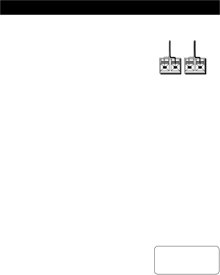
Each speaker - the two main, two surround and one central - has a designated set of terminals on the back panel of the central unit.
Uncoil the speaker wires and locate the bare ends. Press down on the tab to open the red terminal and insert the red (+) wire. Snap the tab closed. Now press down on the black terminal tab and insert the black (-) wire. Snap the tab closed.
WARNING: Be sure to follow these instructions carefully. The system can be damaged if speakers are improperly connected.
SETTING UP FOR SURROUND SOUND
THE MAIN SPEAKERS
The two main speakers should be set between six and 10 feet apart. Putting the speakers any closer or any farther apart may result in distorted sound.
The speakers should also form a 45 degree angle to the central listening point in the room, creating a triangle of listening enjoyment.
NOTE: You may need to place the main speakers closer together when not utilizing the center speaker. Do not place them so close, however, that their magnetic fields affect the TV’s reception.
THE CENTER SPEAKER
For optimal performance, you should try to place the center speaker as close as possible to the same height as the left and right main speakers. You should also try to align all three speakers, or set the center speaker slightly behind the left and right mains. However, you should never place the center speaker forward of the left and right mains, as this will distort the sound for those listeners not seated in the center of the room.
THE SURROUND SPEAKERS
Placement of the surround speakers for optimal performance is truly subject to the size and type of room in which the system is to be placed.
The following are a few position suggestions.
1.Set the speakers on the side walls, facing each other, approximately two to three feet above the listeners head.
2.Aim the speakers directly at the two main speakers, matching height to height. If the room is sparsely decorated, it may be necessary to slightly tilt the speakers down to increase sound quality. If the room is densely decorated, it may be necessary to face the speakers toward the rear wall or at the ceiling.
3.Mount the speakers up on the ceiling. Set them a few feet wide of the listeners and make sure they are facing one another, not the floor.
Obviously there are many more possible positions, so it may be necessary to simply experiment to find the right balance for your situation.
RED BLACK RED BLACK
+ |
– |
+ |
– |
Don’t go solo
You must connect both surround sound speakers for the surround sound speakers to work.
3

INSTALLATION AND SET UP
BALANCING YOUR SPEAKERS
Your system is equipped with  *, which enables you to reproduce sound effects as they were intended. But to do so, the speakers must be correctly balanced.
To balance the speakers using the Test Tone, all speakers must be connected to your amplifier. Your receiver must be in the Dolby Pro Logic Surround Mode.
1.Press the TEST TONE button on the receiver front panel. The Test Tone LED on the front panel will turn on and the amplifier generates a “pink noise” and applies it automatically at three-second intervals to the left main channel, center channel, right main channel and left and right rear channels (simultaneously), in that order.
2.As the pink noise is generated, go to the spot in the room where you are most likely to be when listening to your system. The rear surround and center speakers should be adjusted to equal the level of output from the left and right main speakers.
3.Make adjustments by pressing the REAR/CENTER LEVEL button, and then the +/- button on your remote control. The output from the selected speaker(s) is adjusted accordingly.
Each time you press the + or - button on your remote control to adjust a channel, the receiver provides you with two more seconds of pink noise to that channel before moving on to the next.
4.Press the TEST TONE button again to end the test.
You may not need to check or adjust these levels again unless you move your system, rearrange the speakers, or change your preferred seating location in the room.
NOTE: Fine tuning is best performed with the remote control so that adjustments can be made from the viewing or listening area.
* |
|
Manufactured |
from Dolby Laboratories Licensing Corporation. “Dolby, the |
|
|
double-D |
) and “Pro Logic” are trademarks of Dolby Laboratories Licensing Corporation. |
4
INSTALLATION AND SET UP
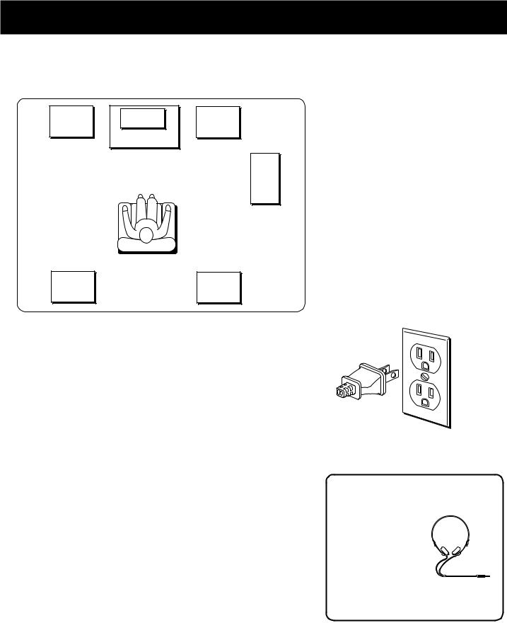
A SAMPLE SET UP FOR SURROUND SOUND ENJOYMENT
LEFT |
CENTER |
RIGHT |
MAIN |
|
MAIN |
|
TV |
|
SUBWOOFER |
OPTIONAL |
LEFT |
RIGHT |
REAR |
REAR |
CONNECTING FOR POWER
Make sure you connect all your other electronic components and your speakers before plugging your receiver into the outlet.
Plug the power cord in the wall outlet, matching the wide blade of the plug with the wide slot in the outlet. Be sure to insert the plug completely.
USING HEADPHONES
To listen privately through your amplifier, use the PHONES jack to the right of the volume dial on the receiver. Headphones are not included.
Have a Blast-Just Not in Your
Eardrums
Make sure that you turn down the stereo before you
put on the headphones; then
increase the volume to the
desired level after they are in place.
5
AMPLIFIER CONTROLS
|
POWER |
|
|
|
|
VOLUME |
|
TEST TONE |
|
|
|
|
|
BALANCE |
BASS |
TREBLE |
TV |
VCR CD VIDEO |
NORMAL WIDE PHANTOM PRO LOGIC 3 STEREO HALL BYPASS |
PHONES |
|
|
|
|
|
|
|
|
|
|
|
|
MIN |
MAX |
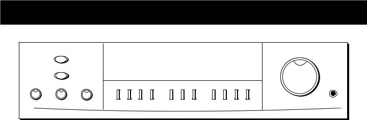
GENERAL CONTROLS
POWER
The POWER button activates or deactivates the amplifier. The unit will default to the last mode it was in before power was removed.
BALANCE
The BALANCE dial allows you to manually adjust the balance of sound coming from your speakers.
BASS
The BASS dial allows you to manually adjust the amount of bass the unit emits.
TREBLE
The TREBLE dial allows you to manually adjust the amount of treble the unit emits.
FUNCTION BUTTONS
The function buttons include TV, VCR, CD and VIDEO.
TEST TONE
The TEST TONE button can only be used in the Dolby Pro Logic and Dolby 3 Stereo mode. This feature allows you to balance your speakers as they emit a sound, called a “pink noise,” in the left, center, right and surround channels sequentially for two seconds each.
NOTE: This process is explained more in-depth in “Balancing Your Speakers,” page 4.
NORMAL
The Normal mode can be activated in both Pro Logic and 3 Stereo. This mode takes the low bass frequencies from the center channel and distributes them to the left and right main speakers to maintain the program’s original integrity.
PHANTOM
The Phantom mode can only be reached while the Pro Logic mode is active. It uses the two main speakers and the two surround speakers. The center speaker is off and the sound that usually comes from it is distributed through the left and right main speakers.
6

AMPLIFIER CONTROLS
WIDE
The WIDE mode can be activated in both the Pro Logic and the 3 Stereo modes. In the Dolby Pro Logic mode, all five speakers are utilized. In the Dolby 3 Stereo mode, just the three front speakers are utilized. All the audio is delivered through the center speaker, which will reproduce the same bass levels as the left and right main speakers.
DOLBY PRO LOGIC
This mode uses all five speakers so the sound envelopes the room.
DOLBY 3 STEREO
This mode uses the two main and one center speaker.
HALL
The Hall mode recreates the effect of listening to a concert or watching a play from inside a music hall. It utilizes the main and surround speakers.
BYPASS
The Bypass mode utilizes just the main speakers.
VOLUME
The Master Volume dial allows you to adjust the level of audio output.
PHONES
The amplifier has been equipped with a PHONES jack. Plug your headphones - not included - into the jack and listen to your favorite media in private.
7
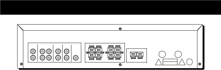
CONNECTING COMPONENTS
TV |
|
VCR |
CD |
VIDEO |
SUB |
IN |
IN |
OUT |
IN |
IN |
WOOFER |
L
R
MAIN SPEAKERS
+ |
R |
- |
- |
+ |
R |
- |
- |
|
|
REAR SPEAKERS |
|
L |
+ |
|
CENTER SPEAKER
L |
+ |
- |
+ |
BEFORE YOU CONNECT...
•Protect components from power surges.
•Connect all components before plugging any power cords into the wall outlet.
•Always turn off the receiver and/or components before you connect or disconnect any cables.
•Always make sure the color-coded plugs match the color of the terminals in which they are inserted. The connection cable plugs and jacks are color-coded as follows:
Speaker Terminals Red for positive (+) terminals. Black for negative (-) terminals.
RCA Phono Type Terminals Red for the right (R) channel. White for the left (L) channel. Yellow for the video (V). Black for the subwoofer. (Cables for video and subwoofer not included.)
•Some units may be supplied with connection plugs that are color coded red and black instead of red and white. In this case, the black plug takes the place of the white plug.
•Contact Consumer Relations if you have questions concerning the connections or components.
POSITION CABLES CORRECTLY TO AVOID
AUDIO HUM OR INTERFERENCE
•Insert all cable plugs firmly into their jacks.
•Place audio/video cables to the sides of the receiver’s back panel instead of straight down the middle after you connect the components.
•Try not to coil any power cables and keep them away from the audio/video cables as much as possible.
•Make sure all antennas and cables are properly grounded. Refer to the Safety Tips sheet packed with your receiver.
PROTECT YOUR COMPONENTS FROM OVERHEATING
•Do not block ventilation holes in any component. Arrange the components so that air can circulate freely.
•Do not stack components directly on top of each other.
•Allow adequate ventilation when placing your components in a stand.
•Place an amplifier near the top shelf of the stand so heating air rising from it will not flow around other components. If you have a satellite receiver, you should place it on the top shelf.
8
 Loading...