


RP-9555

USER‘S
GUIDE
AUDIO SYSTEM
RP-9540
RP-9555
WARNING:
TO PREVENT FIRE
OR ELECTRICAL SHOCK HAZARD,
DO NOT EXPOSE THIS PRODUCT
TO RAIN OR MOISTURE.
SEE MARKING ON BOTTOM / BACK OF PRODUCT
CAUTION
RISK OF ELECTRIC SHOCK
DO NOT OPEN
THE EXCLAMATION
POINT WITHIN THE
TRIANGLE IS A
WARNING SIGN
ALERTING YOU OF
IMPORTANT
INSTRUCTIONS
ACCOMPANYING
THE PRODUCT.
THE LIGHTNING
FLASH AND ARROW-
HEAD WITHIN THE
TRIANGLE IS A
WARNING SIGN
ALERTING YOU OF
"DANGEROUS
VOLTAGE" INSIDE
THE PRODUCT.
CAUTION: TO REDUCE THE
RISK OF ELECTRIC SHOCK,
DO NOT REMOVE COVER
(OR BACK). NO USER-
SERVICEABLE PARTS IN-
SIDE. REFER SERVICING
TO QUALIFIED SERVICE
PERSONNEL.
Important Information Required by the Federal Communications
Commission Concerning Radio Frequency Interference
This device generates and uses radio frequency (RF) energy, and if not installed and used properly, this equipment may
cause interference to radio and television reception.
This equipment has been type tested and found to comply with the limits for a Class B Computing Device in accordance
with the specifications in Subpart J of Part 15 of FCC Rules. These rules are designed to provide reasonable protection
against radio and television interference in a residential installation. However, there is no guarantee that interference
will not occur in particular installations.
If this equipment does cause interference to radio or television reception (which you can determine by turning the
equipment off and on), try to correct the interference by one or more of the following measures:
• Reorient the receiving antenna (that is, the antenna for the radio or television that is “receiving” the interference).
• Move the unit away from the equipment that is receiving interference.
• Plug the unit into a different wall outlet so that the unit and the equipment receiving interference are on different
branch circuits.
If these measures do not eliminate the interference, please consult your dealer or an experienced radio/television
technician for additional suggestions. Also, the Federal Communications Commission has prepared a helpful booklet,
“How To Identify and Resolve Radio TV Interference Problems.” This booklet is available from the U.S. Government
Printing Office, Washington, DC 20402. Please specify stock number 004-000-00345-4 when ordering copies.
Precautions
• Never open the cabinet under any circumstances. Never operate this product with the cabinet removed. Any
repairs or internal adjustments should be made only by a trained service technician.
• Do not touch the pick-up lens which is located inside the disc compartment. Also, to keep dust from collecting on
the pick-up lens, do not leave the compartment door open for an extended period of time. If the lens becomes dirty,
clean it with a soft brush, or use an air blower brush designed for camera lenses.
• Do not touch the player with wet hands. If any liquid enters the player cabinet, take the player to a trained
service technician for inspection.
• This Compact Disc Player uses a laser to read the music on the disc. The laser mechanism corresponds to the
cartridge and stylus of a traditional record player. Although this product incorporates a laser pick-up lens, it is
completely safe when operated according to directions.
For Your Safety
The AC power plug is polarized (one blade is wider than the other) and only fits into AC power outlets
one way. If the plug won’t go into the outlet completely, turn the plug over and try to insert it the
other way. If it still won’t fit, contact a qualified electrician to change the outlet, or use a different one.
Do not attempt to bypass this safety feature.
Service Information
This product should be serviced only by those specially trained in appropriate servicing techniques. For instructions on
how to obtain service, refer to the warranty included in this Guide.
Warning: Never operate this product with the
cabinet removed.
Caution: Use of controls adjustments or
performance of procedures other than those
specified herein may result in hazardous radiation
exposure.
Any repairs or internal adjustments should be
made only by a trained service technician.
For Your Records
In the event that service should be required, you may need both the model number and the serial number. In the space
below, record the date and place of purchase, and the serial number:
Model No. RP-9540/RP-9555
Remote Control No. CRK290A
Date of Purchase ____________________ Place of Purchase _____________________________ Serial No. ________________

1
Where to Start
Owning an RCA compact audio system is like having a
component stereo system, except you don’t have the hassle of
hooking up a bunch of wires.
Looking for a Good Read?
You won’t find this instruction book on the best seller list, but
it does contain a lot of information that you should know
before using your RCA stereo system.
I know that you want to use your stereo, not read about it, but
you really need to read the first section, “First Things First,” to
learn how to hook it up; then, as you have time, you can read
about all of the great features of this stereo.
Don’t Forget the Notes
Don’t forget to read the notes in the margins too. They give
you extra information that can help you get the most from
your stereo.
If you have any questions, be sure to check
the Troubleshooting Tips section, the Index, or the Table of
Contents to help you find the answer.
Table of Contents
First Things First ...................................................2
Before You Begin....................................................2
Installation and Set Up ..................................... 3
General Controls................................................. 4
Using the Tuner ..................................................... 7
Using the CD Player ..............................................9
Using the Cassette Deck .................................... 14
Using the Remote Control .............................. 16
Care and Maintenance .................................... 17
Troubleshooting Tips .......................................18
Index ......................................................................... 19
Limited warranty.............................................. 20
2
First Things First
Be a Pack Rat
It’s a good idea to keep the box and
all of the packing materials when
you’re done unpacking the system in
case you need to store, move, or ship
the unit at a later date.
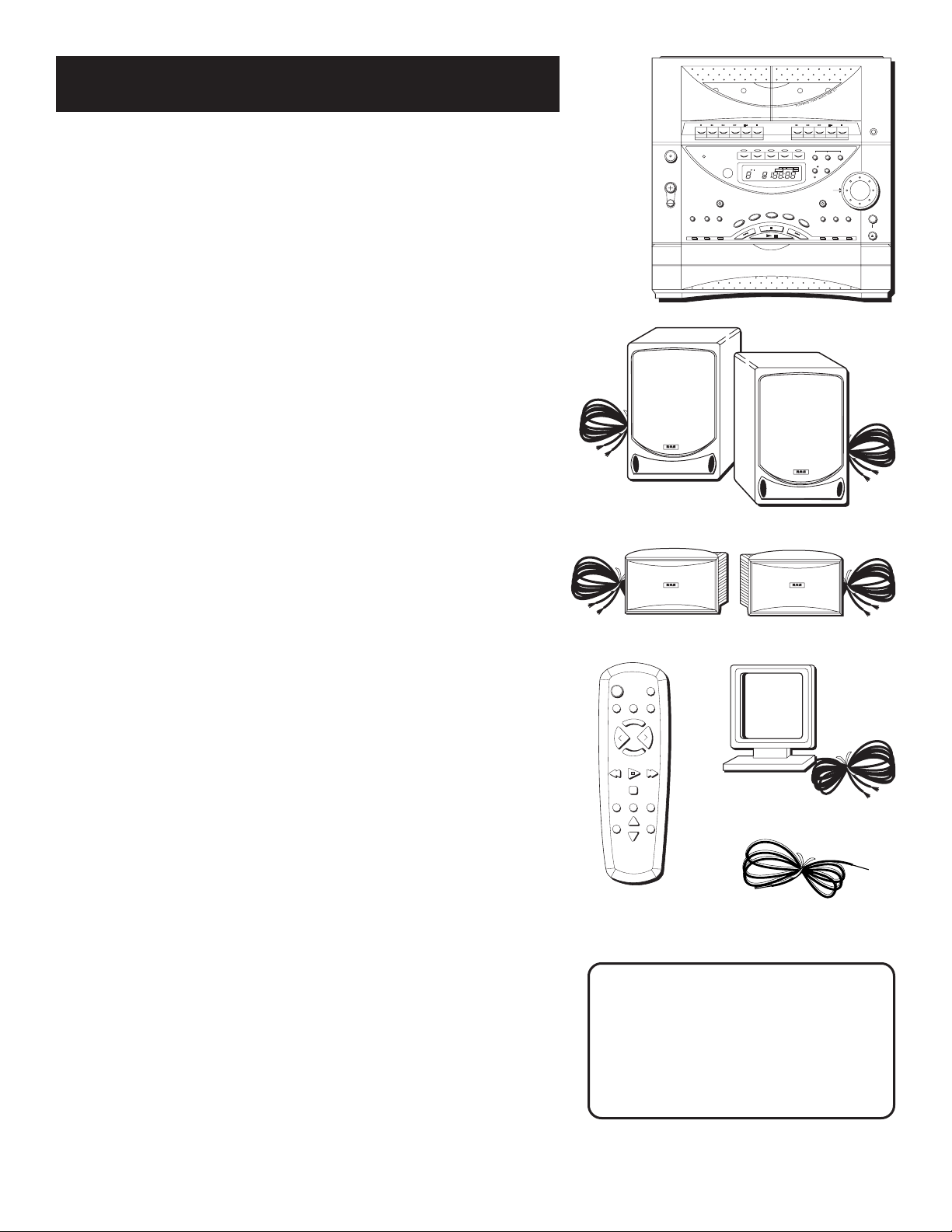
Make sure your package contains all of the items shown to
the right.
Before You Begin
There are a couple of things you need to know in order to
get the best possible performance from your system.
Moisture Condensation
Just as moisture can form on the inside of windows on a cold
day, it can also form on the inside of your stereo, causing it
to malfunction. Some situations in which condensation might
form include the following:
• Immediately after a heater has been turned on
• In a steamy or very humid room
• When the system is suddenly moved from a cold
environment to a warm, moist one; for example, in
moving the stereo from a cool air conditioned room to
an outside porch on a humid, summer day.
If moisture forms inside this player, it may not operate
properly. To correct the problem, turn off the power and
wait about 30 minutes for moisture to evaporate.
Location
These guidelines should be followed when deciding on a
place to put your stereo system:
• Choose a level, solid, surface. Don’t place it on a soft
surface, such as carpeting or foam rubber.
• Choose a location away from direct sunlight, radiators,
air ducts, and other sources of heat.
• Avoid locations that are subject to moisture, mechanical
vibration, shock, or excessive dust.
• Make sure that the location has adequate air circulation.
Good ventilation is essential to protect the system from
internal heat build up.
Speaker Placement
For optimal listening, place speakers at least seven feet apart
and facing the listener.
DECK
1
DECK
2
STANDBY
CD TAPE TUNER
PHONES
VOLUME
BASSBOOST
UP
DOWN
POP CLASSICAL
SELECT
DISC
OPEN/CLOSE
POWER
REMOTE SENSOR
PRESET/TUNE
ROCK
PROGRAM
STEREO
/MONO
SEEK
/SCAN
TUNING
REPEAT INTRO SHUFFLE
DISC 1
DISC 2
DISC 3
DISC 4
DISC 5
CLEAR PROGRAM ATS
100 Hz
1 kHz
10 kHz
STEREO
CUSTOMCLASSICALPOPROCK
BASS BOOST
1 ALL DISC
S
kHz
MHz
REPEAT PROGRAM
INTRO
SHUFFL
REMAINTIMEVOLUME SKIPTRACKAUTO
DISC
VIDEO 1 VIDEO 2
1kHz100 kHz
SRS ( ) CUSTOM
10kHz
3 BAND GRAPHIC EQUALIZER
FM
AM
Unit
FM antenna wire
AM loop antenna
Remote control
CRK290A
POWER
VIDEO
TAPE
CD
STOP
TUNING
SEEKPRESET
TUNER
SHUFFLE
DISC SKIPREPEAT
M
U
T
E
TRACK PLAY
SEARCH
TRACK
SEARCH
E
Q
P
R
E
S
E
T
V
O
L
V
O
L
Speakers
Surround Speakers
3
WARNING:
Be sure to follow these instructions
carefully; the system can be damaged
if speakers are improperly connected.
Installation and Set Up
Now that you’ve chosen a stereo location, it‘s time to hook
it up.
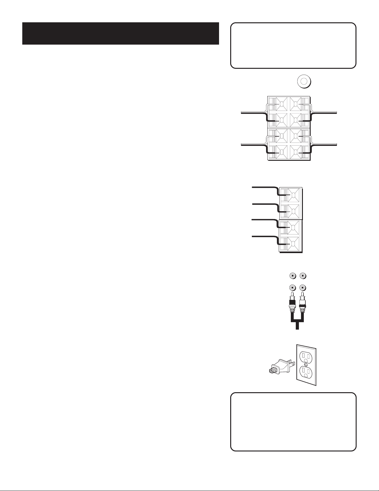
Speakers
Each speaker has its own connection terminals on the back
of the system, so connect the wires from each speaker to
one set of terminals. When connecting the speakers, make
sure that the bare end of each wire makes contact with the
metal grips inside the terminal. There are connections
provided for main and surround speakers The sub-woofer is
an RCA type connecton.
For Each Speaker:
1. Press down on the tab to open the red terminal and
insert the red wire (+) into the red terminal.
2. Press down on the tab to open the black terminal and
insert the black wire (–) into the black terminal.
Antennas
The AM and FM wire antennas connect to the FM ANTENNA
terminals and AM terminal on the system’s back panel, and
must be connected for clear reception. Connect the antenna
wires the same way you connect the speakers.
After connecting the antennas, extend them to their full
length; then you can adjust their position for better
reception when you are listening to the radio.
Auxiliary Components
Use the VIDEO input jacks on the back of the system to add
a component that provides an additional source of sound
into your system (VIDEO 1 or VIDEO 2)— additional VCRs,
camcorders, or other compatible devices.
To hook up an auxiliary component, match the left and
right output plugs from the component to the left (L) and
right (R) VIDEO 1 or VIDEO 2 input jacks on the back panel.
AC Power
Plug the power cord into an AC power outlet that accepts
the polarized plug (one blade wider than the other).
Notice that the Standby Indicator Light comes on to let you
know that the system is plugged in and ready to use. This
light stays on as long as the stereo is plugged in, so that
you can use the remote control to turn on and operate the
system.
Headphones
To listen to your stereo with headphones (not included), use
the
1
/4“ PHONES jack on the front of the system.
Speaker Hookup
FM ANTENNA
300 Ω
AM ANTENNA
Antenna Hookup
R
R L
L
R L
Have a Blast—Just Not on Your
Eardrums
Make sure that you turn down the stereo
before you put on the headphones; then
increase the volume to the desired level
after they are in place.
+
–
RL
8Ω
SPEAKERS
+
–
8Ω
SPEAKERS
SUB WOOFER
MAIN SPEAKERS
SURROUND SPEAKERS
RED
RED
BLACK
BLACK
RED
RED
BLACK
BLACK
VIDEO Component Hookup
4
100 Hz
1 kHz
10 kHz
FM
AM
STEREO
CUSTOMCLASSICALPOPROCK
BASS BOOST
1 ALL DISC
S
kHz
MHz
REPEAT PROGRAM
INTRO
SHUFFLE
REMAIN TIMEVOLUME SKIPTRACKAUTO
DISC
dB
Number
indicator
for Current
Disc
Visual Equalizer presets
Mode indicators
Radio band
indicator
Custom Equalizer Indicator
Bass Boost indicator
Digital display for Tuner
• Tuner Frequency
• CD Time Indicator
Number indicator for:
• Volume level
• Preset radio stations
• CD Track number
• SEEK/SCAN
3 band graphic
equalizer
indicators
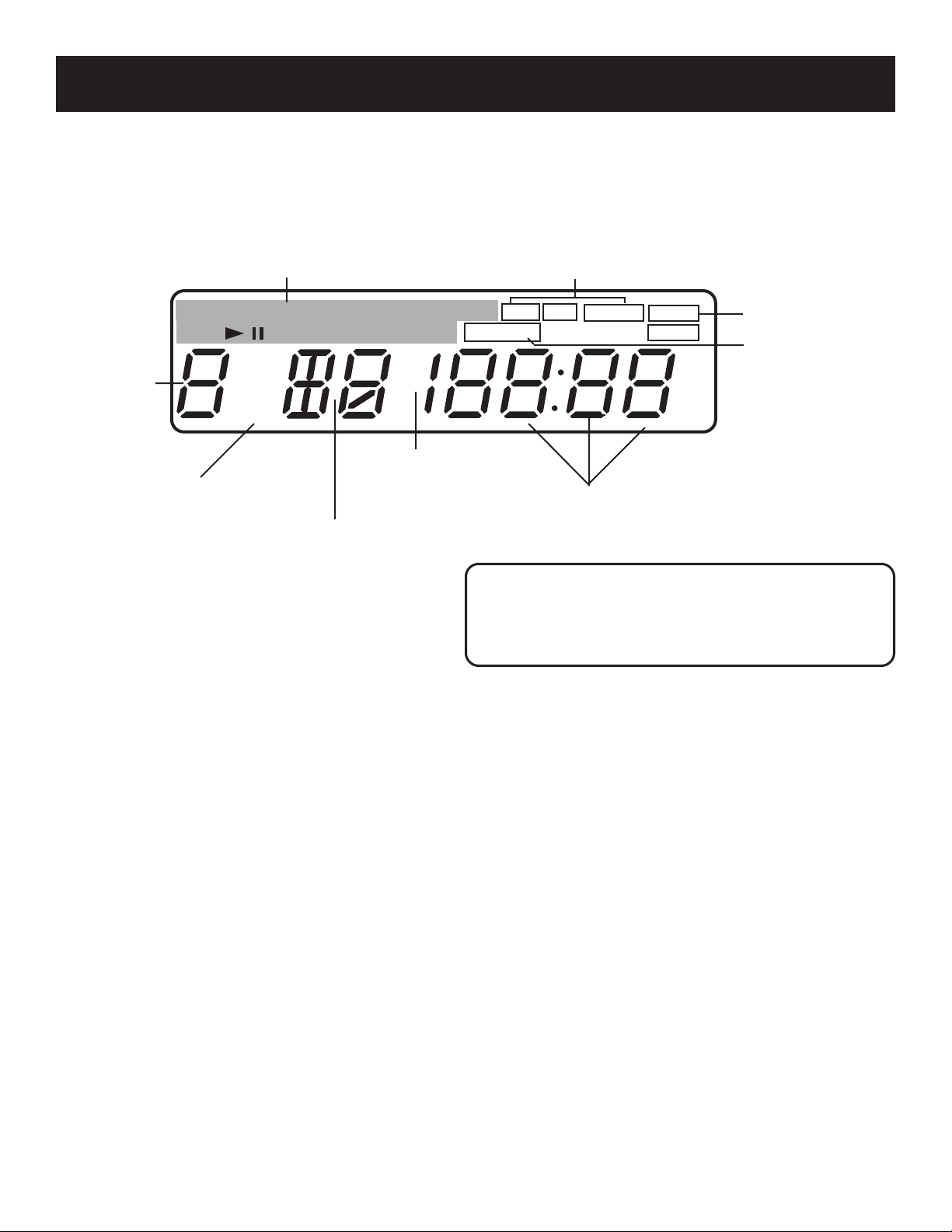
General Controls
The following list of display information is presented in alphabetical order and corresponds to the items
in the preceding graphic.
Bass Boost Indicator. Shows the current setting for Bass Boost.
CD Time Indicator. Indicates whether the playing time displayed is the elapsed time or the time
remaining on a disc. The playing time itself is displayed beneath the indicator.
Digital Display. Shows the current frequency in tuner mode and the track time in CD mode.
Custom Equalizer Indicator. Indicates custom equalizer mode.
Mode Indicators. Show which mode(s) the system is in.
Number Indicator. Depending on the current mode, shows the volume level, the preset number for radio
stations, or the track number of a CD.
Number Indicator. Shows disc number.
Radio Band Indicator. Shows which radio band you are using. When listening
to FM stereo, the STEREO indicator also is displayed (if the station is broadcasting in stereo).
Tuner Frequency. Shows the AM or FM radio frequency.
Visual Equalizer Presets. Shows which preset option (Rock, Pop, or Classical) you have chosen.
3 Band Graphic Equalizer Indicators. Shows which band (100Hz, 1 kHz, or 10kHz) you have chosen.
Don’t Worry
So you think the Panel Display looks intimidating.
Don’t worry, you won’t see all of this stuff at the
same time—you’ll only see what you need to see.
Now you’re ready to use your system, and this section introduces you to the controls and features that are
common to the tape decks, the tuner, and the CD player.
The Panel Display
When the power is on, the Panel Display lights up, telling you what’s going on with your system.
5
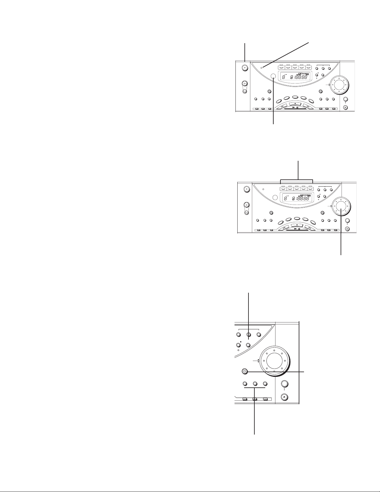
POWER ON
Plug in the system and the standby indicator light comes on.
The system can be operated either by using the remote
control or by pressing the POWER button. Note that the
power button is DIGITAL.
POWER OFF
Press the POWER button on the system or the remote control
to turn off the power and the standby indicator light
comes on.
Remote Sensor
Next to the panel display is the Infrared Remote Control
sensor. Make sure that this is not covered up or blocked, or
the remote control won’t work.
Function Buttons
Use the function buttons (CD, TAPE, TUNER/BAND, VIDEO 1,
or VIDEO 2) to choose which component function you want
to use.
Volume
Turn the volume dial to increase or decrease the volume. The
volume level is displayed numerically in the display
(from 0 mute to 32).
STANDBY
CD TAPE TUNER
VOLUME
BASSBOOST
UP
DOWN
POP CLASSICAL
SELECT
DISC
OPEN/CLOSE
POWER
REMOTE SENSOR
PRESET/TUNE
ROCK
PROGRAM
STEREO
/MONO
SEEK
/SCAN
TUNING
REPEAT INTRO SHUFFLE
DISC 1
DISC 2
DISC 3
DISC 4
DISC 5
CLEAR PROGRAM ATS
100 Hz
1 kHz
10 kHz
STEREO
CUSTOMCLASSICALPOPROCK
BASS BOOST
1 ALL DISC
S
kHz
MHz
REPEAT PROGRAM
INTRO
SHUFFL
REMAIN TIMEVOLUME SKIPTRACKAUTO
DISC
VIDEO 1 VIDEO 2
1kHz100 kHz
SRS ( ) CUSTOM
10kHz
3 BAND GRAPHIC EQUALIZER
FM
AM
Standby Indicator Light
Infrared Remote Control Sensor
Power button
STANDBY
CD TAPE TUNER
VOLUME
BASSBOOST
UP
DOWN
POP CLASSICAL
SELECT
DISC
OPEN/CLOSE
POWER
REMOTE SENSOR
PRESET/TUNE
ROCK
PROGRAM
STEREO
/MONO
SEEK
/SCAN
TUNING
REPEAT INTRO SHUFFLE
DISC 1
DISC 2
DISC 3
DISC 4
DISC 5
CLEAR PROGRAM ATS
100 Hz
1 kHz
10 kHz
STEREO
CUSTOMCLASSICALPOPROCK
BASS BOOST
1 ALL DISC
S
kHz
MHz
REPEAT PROGRAM
INTRO
SHUFFL
REMAIN TIMEVOLUME SKIPTRACKAUTO
DISC
VIDEO 1 VIDEO 2
1kHz100 kHz
SRS ( ) CUSTOM
10kHz
3 BAND GRAPHIC EQUALIZER
FM
AM
Volume
Function buttons
Digital Equalizer
Preset
Pressing the ROCK, POP, or CLASSICAL buttons control the
visual electronic equalizer. Press this button to choose one of
the preset electronic equalizer frequencies. (ROCK, POP, or
CLASSICAL) appears in the display.
Custom
Pressing the CUSTOM button lets you create custom settings.
Press one of the 3 BAND GRAPHIC EQUALIZER buttons and
turn the volume dial to increase or decrease the level of
that frequency band.
Pressing the digital equalizer buttons twice will put you in
the FLAT mode not shown in the display.
VOLUME
BASSBOOST
UP
DOWN
POP CLASSICAL
SELECT
DISC
OPEN/CLOSE
ROCK
CLEAR PROGRAM ATS
1kHz100 kHz
SRS ( ) CUSTOM
10kHz
3 BAND GRAPHIC EQUALIZER
Custom preset button
Bass Boost button
Preset button
 Loading...