


Dragonfly-5 Pro
Raymarine Dragonfly-5 Pro, Dragonfly-4 DVS, Dragonfly-5 M, Dragonfly-7 Pro, Wi-Fish Installation And Operation Instructions Manual
...
INSTALLATION &
OPERATION INSTRUCTIONS
DRAGONFLY

Documentandsoftwarechanges
Thefollowingtablesdescribethemainchangesthathavebeenmadesincethelastreleaseofboththe
productsoftwareandthisdocument.
•Applicablesoftwareversion:Dragony
®
LightHouse
™
II—Release12
•Applicabledocuments:81358–3
•Applicableproducts:Dragony-4DV/Dragony-4DVS/Dragony-4Pro/Dragony-5DVS/
Dragony-5M/Dragony-5Pro/Dragony-7Pro(DoesnotapplytotheWi-Fish
™
product.)
Newfeatures
Description
Applicable
applicationApplicablechapter(s)orsection(s)
AddedsupportforDragony-7ProN/AN/A
Superiordownriggersonarperformance.Sonar/DownVisionN/A
Improvedbottomtrackingcapabilities.
Sonar/DownVisionN/A
Trademarkandpatentsnotice
Raymarine,Tacktick,ClearPulse,Truzoom,HSB,SeaTalk,SeaTalk
hs
,SeaTalk
ng
,Micronet,Raytech,
GearUp,MarineShield,Seahawk,Autohelm,Automagic,andVisionalityareregisteredorclaimed
trademarksofRaymarineBelgium.
FLIR,DownVision,SideVision,Dragony,Quantum,Instalert,InfraredEverywhere,andTheWorld’s
SixthSenseareregisteredorclaimedtrademarksofFLIRSystems,Inc.
Allothertrademarks,tradenames,orcompanynamesreferencedhereinareusedforidenticationonly
andarethepropertyoftheirrespectiveowners.
Thisproductisprotectedbypatents,designpatents,patentspending,ordesignpatentspending.
FairUseStatement
Youmayprintnomorethanthreecopiesofthismanualforyourownuse.Youmaynotmakeanyfurther
copiesordistributeorusethemanualinanyotherwayincludingwithoutlimitationexploitingthemanual
commerciallyorgivingorsellingcopiestothirdparties.

Contents
Chapter1Importantinformation..........................7
TFTDisplays...............................................................8
Wateringress..............................................................8
Disclaimers.................................................................8
Memorycardsandchartcards.....................................8
EMCinstallationguidelines..........................................8
RFexposure...............................................................9
FCC............................................................................9
ComplianceStatement(Part15.19)..............................9
FCCInterferenceStatement(Part15.105(b))...............9
IndustryCanada..........................................................9
IndustryCanada(Français)..........................................9
Japaneseapprovals...................................................10
Thirdpartysoftwarelicenseagreements.....................10
Declarationofconformity............................................10
Pixeldefectpolicy......................................................10
Warrantypolicy..........................................................10
Warrantyregistration..................................................10
Productdisposal........................................................10
IMOandSOLAS........................................................10
Technicalaccuracy....................................................10
Chapter2Documentandproduct
information...........................................................13
2.1Documentinformation..........................................14
2.2Productoverview.................................................16
2.3CHIRPDownVision
™
overview..............................17
2.4CHIRPSonaroverview.........................................17
Chapter3Planningtheinstallation...................19
3.1Installationchecklist.............................................20
3.2Partssupplied–DV,DVS,andProvariants...........20
3.3Partssupplied–5M.............................................21
3.4Partssupplied—Wi-Fish
™
...................................21
3.5DownVision
™
transducercompatibility..................22
3.6T oolsrequiredforinstallation—Dragony
®
DV
/DVS/Pro/Wi-Fish
™
..............................................23
3.7Toolsrequiredforinstallation—Dragony-5
M..............................................................................23
3.8Softwareupdates.................................................24
3.9Warningsandcautions.........................................24
3.10Selectingalocationforthetransducer.................25
3.11Cablerouting......................................................26
3.12Selectingalocationforthedisplay.......................26
3.13Installationprocess.............................................28
Chapter4Mounting.............................................29
4.1Mountingthetransommountbracket.....................30
4.2Mountingthetransducer.......................................30
4.3Mountingtheunit.................................................31
4.4T estingandadjustingthetransducer.....................32
4.5Finalizingthetransducermounting........................33
Chapter5Cablesandconnections....................35
5.1Generalcablingguidance.....................................36
5.2Connectionsoverview..........................................36
5.3Cableconnection–DV,DVS,Proand
Wi-Fish
™
..................................................................38
5.4Connectingthepowercable-5M.........................38
5.5Extensioncableconnection..................................41
Chapter6Wi-Fish
™
.............................................43
6.1Wi-Fishcontrols...................................................44
6.2Switchingtheunitonandoff.................................44
6.3Wi-Fish
™
mobileapp...........................................45
6.4Wi-Fish
™
initialsetup..........................................46
6.5DepthOffset........................................................46
6.6Switchingonthesimulator—Wi-Fish
™
app...........47
6.7OpeningtheMicroSDcardreadercover................47
Chapter7Gettingstarted...................................49
7.1Controls—DV,DVS,ProandM..........................50
7.2Switchingtheunitonandoff.................................50
7.3Initialsetupprocedures........................................51
7.4Satellite-basednavigation.....................................52
7.5Checkingthesonarapplication.............................53
7.6CheckingtheDownVision
™
application................54
7.7Shortcutspage.....................................................54
7.8Applications.........................................................55
7.9Viewswitcher.......................................................56
7.10Memorycardsandchartcards............................57
7.11Learningresources.............................................58
Chapter8Fishnderapplications......................59
8.1DownVision
™
applicationoverview.......................60
8.2Sonarapplicationoverview...................................60
8.3Fishnderapplications'features............................62
8.4Fishnderapplications’controls............................62
8.5Zoom..................................................................63
8.6Range.................................................................64
8.7Scrolling..............................................................64
8.8A-Scopemode.....................................................65
8.9DisplayOptions....................................................65
8.10Colors...............................................................66
8.11Sensitivityadjustments.......................................67
8.12DVSystemsettingsmenuoptions.......................68
Chapter9Chartapplication................................69
9.1Chartapplicationoverview....................................70
9.2Electronicchartsoverview....................................71
9.3Chartapplicationcontrols.....................................73
9.4Waypointsoverview.............................................74
9.5Tracks.................................................................81
9.6ImportandExport................................................83
9.7Waypointsandtracksstoragecapacity..................84
9.8Navigation...........................................................84
9.9Chartsettingsmenu—cartography
compatibility..............................................................85
5

9.10Chartselection...................................................86
9.11ChartDetail........................................................86
9.12Highresolutionbathymetry.................................87
9.13Chartorientation................................................87
9.14T extandSymbolsize..........................................88
9.15Boatposition......................................................89
9.16Communitylayer................................................89
9.17Sonarlogging.....................................................90
9.18COGV ector.......................................................90
9.19DeepWater.......................................................91
9.20Chartobjects.....................................................91
9.215MSystemsettingsmenu..................................92
Chapter10Mobileapplications..........................93
10.1Wi-Fish
™
mobileapp..........................................94
10.2ConnectingWi-Fi—Prodisplays........................94
Chapter11Tools&Settings...............................95
11.1SystemSettingsmenu........................................96
11.2Alarms.............................................................102
11.3Backupandreset.............................................105
11.4Wi-FiSettings...................................................107
Chapter12Maintenance...................................109
12.1Serviceandmaintenance..................................110
12.2Productcleaning...............................................110
12.3Transducercleaning..........................................111
Chapter13Troubleshooting.............................113
13.1Troubleshooting................................................1 14
13.2Poweruptroubleshooting..................................115
13.3GPStroubleshooting.........................................116
13.4Sonar/DownVisiontroubleshooting...................1 17
13.5Wi-Fitroubleshooting.........................................119
13.6Miscellaneoustroubleshooting..........................121
Chapter14Technicalsupport..........................123
14.1Raymarineproductsupportandservicing...........124
14.2Learningresources...........................................125
Chapter15Technicalspecication..................127
15.1T echnicalspecication—Dragony-4................128
15.2T echnicalspecication—Dragony-5................129
15.3T echnicalspecication—Dragony-7................130
15.4T echnicalspecication—Wi-Fish
™
...................131
15.5T echnicalspecication—CPT-DVand
CPT-DVS................................................................131
Chapter16Sparesandaccessories................133
16.1Spares&Accessories......................................134
6
Dragony–4/Dragony–5/Dragony–7/Wi–Fish
Chapter1:Importantinformation
Warning:Productinstallationand
operation
•Thisproductmustbeinstalledand
operatedinaccordancewiththe
instructionsprovided.Failuretodoso
couldresultinpersonalinjury,damage
toyourvesseland/orpoorproduct
performance.
•Raymarinerecommendscertied
installationbyaRaymarineapproved
installer.Acertiedinstallationqualies
forenhancedproductwarrantybenets.
ContactyourRaymarinedealerfor
furtherdetails,andrefertotheseparate
warrantydocumentpackedwithyour
product.
Warning:Ensuresafenavigation
Thisproductisintendedonlyasanaid
tonavigationandmustneverbeused
inpreferencetosoundnavigational
judgment.Onlyofcialgovernment
chartsandnoticestomarinerscontainall
thecurrentinformationneededforsafe
navigation,andthecaptainisresponsible
fortheirprudentuse.Itistheuser’s
responsibilitytouseofcialgovernment
charts,noticestomariners,cautionand
propernavigationalskillwhenoperating
thisoranyotherRaymarineproduct.
Warning:Potentialignitionsource
ThisproductisNOTapprovedforusein
hazardous/ammableatmospheres.Do
NOTinstallinahazardous/ammable
atmosphere(suchasinanengineroom
ornearfueltanks).
Warning:12Voltdconly
Thisproductmustonlybeconnectedtoa
12voltdcpowersource.
Warning:Highvoltages
Thisproductmaycontainhighvoltages.
DoNOTremoveanycoversorotherwise
attempttoaccessinternalcomponents,
unlessspecicallyinstructedinthe
documentationprovided.
Warning:Powersupplyvoltage
Connectingthisproducttoavoltage
supplygreaterthanthespecied
maximumratingmaycausepermanent
damagetotheunit.RefertotheT echnical
specicationsectionforvoltagerating.
Warning:Productgrounding
Beforeapplyingpowertothisproduct,
ensureithasbeencorrectlygrounded,in
accordancewiththeinstructionsprovided.
Warning:Switchoffpowersupply
Ensurethevessel’spowersupplyis
switchedOFFbeforestartingtoinstallthis
product.DoNOTconnectordisconnect
equipmentwiththepowerswitchedon,
unlessinstructedinthisdocument.
Warning:FCCWarning(Part15.21)
Changesormodicationstothis
equipmentnotexpresslyapprovedin
writingbyRaymarineIncorporatedcould
violatecompliancewithFCCrulesand
voidtheuser’sauthoritytooperatethe
equipment.
Caution:Serviceandmaintenance
Thisproductcontainsnouserserviceable
components.Pleasereferallmaintenance
andrepairtoauthorizedRaymarine
dealers.Unauthorizedrepairmayaffect
yourwarranty.
Caution:Transducercable
•DoNOTcut,shorten,orsplicethe
transducercable.
•DoNOTremovetheconnector.
Ifthecableiscut,itcannotberepaired.
Cuttingthecablewillalsovoidthe
warranty.
Caution:Powersupplyprotection
Wheninstallingthisproductensurethe
powersourceisadequatelyprotected
bymeansofasuitably-ratedfuseor
automaticcircuitbreaker.
Caution:Careofchartandmemory
cards
Toavoidirreparabledamagetoand/or
lossofdatafromchartandmemorycards:
•DONOTsavedataorlestoacard
containingcartographyasthecharts
maybeoverwritten.
•Ensurethatchartandmemorycards
arettedthecorrectwayaround.DO
NOTtrytoforceacardintoposition.
•DONOTuseametallicinstrumentsuch
asascrewdriverorplierstoinsertor
removeachartormemorycard.
Importantinformation
7

Caution:Ensurecardreaderdoor
issecurelyclosed
Topreventwateringressandconsequent
damagetotheproduct,ensurethatthe
cardreaderdoorisrmlyclosed.
Caution:Productcleaning
Whencleaningproducts:
•Ifyourproductincludesadisplay
screen,doNOTwipethescreenwith
adrycloth,asthiscouldscratchthe
screencoating.
•DoNOTuseabrasive,oracidor
ammoniabasedproducts.
•DoNOTuseajetwash.
TFTDisplays
Thecolorsofthedisplaymayseemtovarywhen
viewedagainstacoloredbackgroundorincolored
light.Thisisaperfectlynormaleffectthatcan
beseenwithallcolorThinFilmTransistor(TFT)
displays.
Wateringress
Wateringressdisclaimer
Althoughthewaterproofratingcapacityofthis
productmeetsthestatedIPXstandard(refertothe
product’sT echnicalSpecication),waterintrusion
andsubsequentequipmentfailuremayoccurifthe
productissubjectedtocommercialhigh-pressure
washing.Raymarinewillnotwarrantproducts
subjectedtohigh-pressurewashing.
Disclaimers
Thisproduct(includingtheelectroniccharts)is
intendedtobeusedonlyasanaidtonavigation.It
isdesignedtofacilitateuseofofcialgovernment
charts,notreplacethem.Onlyofcialgovernment
chartsandnoticestomarinerscontainallthecurrent
informationneededforsafenavigation,andthe
captainisresponsiblefortheirprudentuse.Itis
theuser’sresponsibilitytouseofcialgovernment
charts,noticestomariners,cautionandproper
navigationalskillwhenoperatingthisoranyother
Raymarineproduct.Thisproductsupportselectronic
chartsprovidedbythirdpartydatasupplierswhich
maybeembeddedorstoredonmemorycard.Use
ofsuchchartsissubjecttothesupplier’sEnd-User
LicenceAgreementincludedinthedocumentation
forthisproductorsuppliedwiththememorycard
(asapplicable).
Raymarinedoesnotwarrantthatthisproductis
error-freeorthatitiscompatiblewithproducts
manufacturedbyanypersonorentityotherthan
Raymarine.
Thisproductusesdigitalchartdata,andelectronic
informationfromtheGlobalPositioningSystem
(GPS)whichmaycontainerrors.Raymarinedoes
notwarranttheaccuracyofsuchinformationand
youareadvisedthaterrorsinsuchinformationmay
causetheproducttomalfunction.Raymarineisnot
responsiblefordamagesorinjuriescausedbyyour
useorinabilitytousetheproduct,bytheinteraction
oftheproductwithproductsmanufacturedbyothers,
orbyerrorsinchartdataorinformationutilizedby
theproductandsuppliedbythirdparties.
Memorycardsandchartcards
MicroSD memory cards can be used to back up /
archive data (e.g. Waypoint, and Tracks). Once
dataisbackeduptoamemorycardolddatacan
bedeletedfromthesystem,creatingcapacityfor
newdata.Thearchiveddatacanberetrievedatany
time.Chartcardsprovideadditionalorupgraded
cartography.
Itisrecommendedthatyourdataisbackeduptoa
memorycardonaregularbasis.DoNOTsavedata
toamemorycardcontainingcartography.
Compatiblecards
ThefollowingtypesofMicroSDcardsarecompatible
withyourdisplay:
•MicroSecureDigitalStandard-Capacity
(MicroSDSC)
•MicroSecureDigitalHigh-Capacity(MicroSDHC)
Note:
•Themaximumsupportedmemorycardcapacity
is32GB.
•MicroSDcardsmustbeformattedtouseeither
theFATorFAT32lesystemformattoenable
usewithyourMFD.
Speedclassrating
Forbestperformanceitisrecommendedthatyou
useClass10orUHS(UltraHighSpeed)class
memorycards.
Chartcards
Yourproductispre-loadedwithelectroniccharts
(worldwidebasemap).Ifyouwishtousedifferent
chartdata,youcaninsertcompatiblechartcardsinto
theunit'smemorycardreader.
Usebrandedchartcardsandmemorycards
Whenarchivingdataorcreatinganelectronicchart
card,Raymarinerecommendstheuseofquality
brandedmemorycards.Somebrandsofmemory
cardmaynotworkinyourunit.Pleasecontact
customersupportforalistofrecommendedcards.
EMCinstallationguidelines
Raymarineequipmentandaccessoriesconformto
theappropriateElectromagneticCompatibility(EMC)
regulations,tominimizeelectromagneticinterference
8
Dragony–4/Dragony–5/Dragony–7/Wi–Fish

betweenequipmentandminimizetheeffectsuch
interferencecouldhaveontheperformanceofyour
system
CorrectinstallationisrequiredtoensurethatEMC
performanceisnotcompromised.
Note:InareasofextremeEMCinterference,
someslightinterferencemaybenoticedonthe
product.Wherethisoccurstheproductandthe
sourceoftheinterferenceshouldbeseparatedby
agreaterdistance.
ForoptimumEMCperformancewerecommend
thatwhereverpossible:
•Raymarineequipmentandcablesconnectedto
itare:
–Atleast1m(3ft)fromanyequipment
transmittingorcablescarryingradiosignalse.g.
VHFradios,cablesandantennas.Inthecase
ofSSBradios,thedistanceshouldbeincreased
to7ft(2m).
–Morethan2m(7ft)fromthepathofaradar
beam.Aradarbeamcannormallybeassumed
tospread20degreesaboveandbelowthe
radiatingelement.
•Theproductissuppliedfromaseparatebattery
fromthatusedforenginestart.Thisisimportantto
preventerraticbehavioranddatalosswhichcan
occuriftheenginestartdoesnothaveaseparate
battery.
•Raymarinespeciedcablesareused.
•Cablesarenotcutorextended,unlessdoingsois
detailedintheinstallationmanual.
Note:Whereconstraintsontheinstallation
preventanyoftheaboverecommendations,
alwaysensurethemaximumpossibleseparation
betweendifferentitemsofelectricalequipment,to
providethebestconditionsforEMCperformance
throughouttheinstallation
RFexposure
ThisequipmentcomplieswithFCC/ICRFexposure
limitsforgeneralpopulation/uncontrolledexposure.
ThewirelessLAN/Bluetoothantennaismounted
behindthefrontfaciaofthedisplay .Thisequipment
shouldbeinstalledandoperatedwithaminimum
distanceof1cm(0.39in)betweenthedeviceand
thebody .Thistransmittermustnotbeco-located
oroperatinginconjunctionwithanyotherantenna
ortransmitter,exceptinaccordancewithFCC
multi-transmitterproductprocedures.
FCC
ComplianceStatement(Part15.19)
ThisdevicecomplieswithPart15oftheFCCRules.
Operationissubjecttothefollowingtwoconditions:
1.Thisdevicemaynotcauseharmfulinterference.
2.Thisdevicemustacceptanyinterference
received,includinginterferencethatmaycause
undesiredoperation.
FCCInterferenceStatement(Part
15.105(b))
Thisequipmenthasbeentestedandfoundtocomply
withthelimitsforaClassBdigitaldevice,pursuant
toPart15oftheFCCRules.
Theselimitsaredesignedtoprovidereasonable
protectionagainstharmfulinterferenceina
residentialinstallation.Thisequipmentgenerates,
uses,andcanradiateradiofrequencyenergyand,
ifnotinstalledandusedinaccordancewiththe
instructions,maycauseharmfulinterferencetoradio
communications.However,thereisnoguarantee
thatinterferencewillnotoccurinaparticular
installation.Ifthisequipmentdoescauseharmful
interferencetoradioortelevisionreception,which
canbedeterminedbyturningtheequipmentoff
andon,theuserisencouragedtotrytocorrectthe
interferencebyoneofthefollowingmeasures:
1.Reorientorrelocatethereceivingantenna.
2.Increasetheseparationbetweentheequipment
andreceiver.
3.Connecttheequipmentintoanoutletona
circuitdifferentfromthattowhichthereceiver
isconnected.
4.Consultthedealeroranexperiencedradio/TV
technicianforhelp.
IndustryCanada
ThisdevicecomplieswithIndustryCanada
License-exemptRSSstandard(s).
Operationissubjecttothefollowingtwoconditions:
1.Thisdevicemaynotcauseinterference;and
2.Thisdevicemustacceptanyinterference,
includinginterferencethatmaycauseundesired
operationofthedevice.
ThisClassBdigitalapparatuscomplieswith
CanadianICES-003.
IndustryCanada(Français)
Cetappareilestconformeauxnormesd'exemption
delicenceRSSd'IndustryCanada.
Sonfonctionnementestsoumisauxdeuxconditions
suivantes:
1.cetappareilnedoitpascauserd'interférence,et
2.cetappareildoitacceptertouteinterférence,
notammentlesinterférencesquipeuventaffecter
sonfonctionnement.
CetappareilnumériquedelaclasseBestconforme
àlanormeNMB-003duCanada.
Importantinformation
9

Japaneseapprovals
Inthefrequencybandusedforthisdevice,campusradio
stations(radiosstationsthatrequirealicense)andspecied
lowpowerradiostations(radiostationsthatdonotrequire
license)formobileidenticationandamateurradiostations
(radiostationsthatrequirelicense)usedinindustriessuchas
microwaveovens,scientic,medicalequipmentdevicesand
productionlineofotherfactoriesarealsobeingoperated.
1.Beforeusingthisdevice,pleasemakesurethatcampus
radiostationsandspeciedlowpowerradiostationsfor
mobileidenticationandamateurradiostationsarenot
beingoperatednearby.
2.Incasethereisanycaseofharmfulinterferenceto
campusradiostationsformobileidenticationcausedby
thisdevice,pleaseimmediatelychangethefrequency
usedorstopthetransmissionofradiowavesandthen
consultaboutthemeasurestoavoidinterference(for
example,theinstallationofpartitions)throughthecontact
informationbelow.
3.Besides,whenintrouble,suchaswhenthereisany
caseofharmfulinterferencetospeciedlowpower
radiostationsformobileidenticationoramateurradio
stationscausedbythisdevice,pleaseconsultthrough
thefollowingcontactinformation.
Contactinformation:Pleasecontactyourlocalauthorized
Raymarinedealer.
Thirdpartysoftwarelicense
agreements
Thisproductissubjecttocertainthirdpartysoftware
licenseagreementsaslistedbelow:
•GNU—LGPL/GPL
•JPEGlibraries
•OpenSSL
•FreeType
Declarationofconformity
RaymarineUKLtd.declaresthatthisproductis
compliantwiththeessentialrequirementsofR&TTE
directive1999/5/EC.
Pixeldefectpolicy
IncommonwithallTFTunits,thescreenmayexhibit
afewwrongly-illuminated(“dead”)pixels.These
mayappearasblackpixelsinalightareaofthe
screenorascoloredpixelsinblackareas.
IfyourdisplayexhibitsMOREthanthenumber
ofwrongly-illuminatedpixelsallowed(refertothe
producttechnicalspecicationfordetails),please
contactyourlocalRaymarineservicecenterfor
furtheradvice.
Warrantypolicy
Yourproductiswarrantedtobefreefromdefectsin
materialsandworkmanshipforaperiodof1year
fromthedateofrstpurchaseoftheproductor,if
installedonanewboat,thedateofrstboatdelivery
totheOriginalCustomer(pleaseretainproofof
purchaseincaseyouneedtoclaim).
Warrantyregistration
Itisimportantthatyouregisteryourproductto
receivefullwarrantybenets.Yourunitpackage
includesabarcodelabelindicatingtheserialnumber
oftheunit.Youwillneedthisserialnumberwhen
registeringyourproductonline.Youshouldretain
thelabelforfuturereference.
Productdisposal
Disposeofthisproductinaccordancewiththe
WEEEDirective.
TheWasteElectricalandElectronicEquipment
(WEEE)Directiverequirestherecyclingofwaste
electricalandelectronicequipment.
IMOandSOLAS
Theequipmentdescribedwithinthisdocument
isintendedforuseonleisuremarineboatsand
workboatsNOTcoveredbyInternationalMaritime
Organization(IMO)andSafetyofLifeatSea
(SOLAS)CarriageRegulations.
10
Dragony–4/Dragony–5/Dragony–7/Wi–Fish

Chapter2:Documentandproductinformation
Chaptercontents
•2.1Documentinformationonpage14
•2.2Productoverviewonpage16
•2.3CHIRPDownVision
™
overviewonpage17
•2.4CHIRPSonaroverviewonpage17
Documentandproductinformation
13
2.1Documentinformation
Thisdocumentcontainsimportantinformation
relatedtotheinstallationofyourRaymarineproduct.
Thedocumentincludesinformationtohelpyou:
•planyourinstallationandensureyouhaveallthe
necessaryequipment;
•installandconnectyourproductaspartofawider
systemofconnectedmarineelectronics;
•troubleshootproblemsandobtaintechnical
supportifrequired.
Applicableproducts
Thisdocumentisapplicabletothefollowingproducts:
Part
numberDescription
E70291
Dragony-4DV
Standalonesinglechannel
Fishnderdisplaywith
transducer
E70292
Dragony-4DVS
Standalonedualchannel
Fishnderdisplaywith
transducer
E70294
Dragony-4Pro
Standalonedualchannel
Fishnder/Chartplotter
displaywithtransducer
E70306
Dragony-5DVS
Standalonedualchannel
Fishnderdisplaywith
transducer
E70293
Dragony-5Pro
Standalonedualchannel
Fishnder/Chartplotter
displaywithtransducer
E70295
Dragony-5MStandalone
Chartplotterdisplay
E70320
Dragony-7Pro
Standalonedualchannel
Fishnder/Chartplotter
displaywithtransducer
E70290
Wi-Fish
™
Standalone
singlechannelWi-Fisonar
module
Note:Dragony
®
productsarestandalone
non-networkableproducts.
Applicablechapters
Somechaptersinthismanualareonlyapplicable
tocertainproductvariants.Thetablebelowshows
whichchaptersareapplicabletoeachproduct
variant.
ChapterVariant
Chapter1Important
information
All
Chapter2Documentand
productinformation
All
Chapter3Planningthe
installation
All
Chapter4Mounting
All
Chapter5Cablesand
connections
All
Chapter6Wi-Fish
™
Wi-Fish
™
Chapter7GettingstartedDV,DVS,MandPro
Chapter8Fishnder
applications
DV,DVSandPro
Chapter9Chartapplication
MandPro
Chapter10Mobile
applications
Pro
Chapter11Tools&SettingsDVSandPro
Chapter12Maintenance
All
Chapter13Troubleshooting
All
Chapter14T echnicalsupport
All
Chapter15Technical
specication
All
Chapter16Sparesand
accessories
All
Softwarerevision
Productsoftwareisupdatedregularlytoaddnew
featuresandimproveexistingfunctionality .
Release 12
14
Dragony–4/Dragony–5/Dragony–7/Wi–Fish

Productdocumentation
Thefollowingdocumentationisapplicabletoyour
product:
DescriptionPartnumber
Dragony-4,Dragony-5,
Dragony-7andWi-Fish
™
installation
andoperationinstructions
Installationandoperationalinstructions
fortheDragony
®
rangeofproductsand
theCPT-DVandCPT-DVStransducer
81358
Dragony-4,Dragony-5,
Dragony-7andWi-Fish
™
surface
mountkitinstallationinstructions
InstallationofaDragony
®
usingthe
surfacemountadaptorkit.
87259
CPT-DVandCPT-DVSTransommount
transducermountingtemplate
87238
Documentconventions
Thefollowingconventionsareusedthroughoutthis
handbook.
Select
Theterm‘Select’isusedtodescribetheactionof
usingtheproduct’sdirectionalcontrolstohighlight
anitemandthenpressingtheOKbuttontoconrm
theselection.
Directionalcontrols
Theterm‘Directionalcontrols’isusedtodescribe
theUp,Down,LeftandRightcontrols.
Documentillustrations
Yourproductmaydifferslightlyfromthatshown
intheillustrationsinthisdocument,dependingon
productvariantanddateofmanufacture.
Allimagesareprovidedforillustrationpurposesonly.
UsermanualsPrintShop
RaymarineprovidesaPrintShopservice,enabling
youtopurchaseahigh-quality ,professionally-printed
manualforyourRaymarineproduct.
Printedmanualsareidealforkeepingonboardyour
vessel,asausefulsourceofreferencewhenever
youneedassistancewithyourRaymarineproduct.
Note:
•Acceptedmethodsofpaymentforprinted
manualsarecreditcardsandPayPal.
•Printedmanualscanbeshippedworldwide.
•FurthermanualswillbeaddedtothePrintShop
overthecomingmonthsforbothnewandlegacy
products.
•Raymarineusermanualsarealsoavailableto
downloadfree-of-chargefromtheRaymarine
website,inthepopularPDFformat.ThesePDF
lescanbeviewedonaPC/laptop,tablet,
smartphone,oronthelatestgenerationof
Raymarinemultifunctiondisplays.
Documentandproductinformation
15
2.2Productoverview
Dragony
®
productsarestandaloneFishnderand/
orChartplotterproducts.
D13240-1
Thefollowingproductsareavailable:
ProductFeatures
Wi-Fish
™
•1xCHIRPDownVision
™
channel
•SuppliedwithCPT-DV(CHIRP
DownVision
™
andtemperaturetransom
mounttransducer
•Built-inWi-Fi(displayonAndroid4and
iOS7compatiblesmartdevices)
•Easyballandsocketdisplaymounting
Dragony-4DV
•4.3’BrightallweatherLEDbacklit
display
•1xCHIRPDownVision
™
channel
•SuppliedwithCPT-DV(CHIRP
DownVision
™
andtemperaturetransom
mounttransducer
•Easyballandsocketdisplaymounting
Dragony-4
DVS
•4.3’BrightallweatherLEDbacklit
display
•DualchannelCHIRPDownVision
™
and
CHIRPSonarchannels.
•SuppliedwithCPT-DVS(Combined
CHIRPDownVision
™
,CHIRPsonar
andtemperaturetransommount
transducer
•Easyballandsocketdisplaymounting
Dragony-4
Pro
•4.3’BrightallweatherLEDbacklit
display
•DualchannelCHIRPDownVision
™
and
CHIRPSonarchannels.
•SuppliedwithCPT-DVS(Combined
CHIRPDownVision
™
,CHIRPsonar
andtemperaturetransommount
transducer
•Easyballandsocketdisplaymounting
•Built-inWi-Fi(displayonAndroid4and
iOS7compatiblesmartdevices)
ProductFeatures
•Built-inGNSS(GPS/GLONASS)
receiver
•CompatiblewithLightHouse
™
charts,
Navionics
®
andC-Mapchartsby
Jeppesen
®
Dragony-5
DVS
•5’BrightallweatherLEDbacklitdisplay
•DualchannelCHIRPDownVision
™
and
CHIRPSonarchannels.
•SuppliedwithCPT-DVS(Combined
CHIRPDownVision
™
,CHIRPsonar
andtemperaturetransommount
transducer
•Easyballandsocketdisplaymounting
Dragony-5
Pro
•5’BrightallweatherLEDbacklitdisplay
•DualchannelCHIRPDownVision
™
and
CHIRPSonarchannels.
•SuppliedwithCPT-DVS(Combined
CHIRPDownVision
™
,CHIRPsonar
andtemperaturetransommount
transducer
•Easyballandsocketdisplaymounting
•Built-inWi-Fi(displayonAndroid4and
iOS7compatiblesmartdevices)
•Built-inGNSS(GPS/GLONASS)
receiver
•CompatiblewithLightHouse
™
charts,
Navionics
®
andC-Mapchartsby
Jeppesen
®
Dragony-5M
•5’BrightallweatherLEDbacklitdisplay
•Easyballandsocketdisplaymounting
•Built-inGNSS(GPS/GLONASS)
receiver
•CompatiblewithLightHouse
™
charts,
Navionics
®
andC-Mapchartsby
Jeppesen
®
Dragony-7
Pro
•7’BrightallweatherLEDbacklitdisplay
•DualchannelCHIRPDownVision
™
and
CHIRPSonarchannels.
•SuppliedwithCPT-DVS(Combined
CHIRPDownVision
™
,CHIRPsonar
andtemperaturetransommount
transducer
•Easyballandsocketdisplaymounting
•Built-inWi-Fi(displayonAndroid4and
iOS7compatiblesmartdevices)
•Built-inGNSS(GPS/GLONASS)
receiver
•CompatiblewithLightHouse
™
charts,
Navionics
®
andC-Mapchartsby
Jeppesen
®
16
Dragony–4/Dragony–5/Dragony–7/Wi–Fish
2.3CHIRPDownVision
™
overview
DownVision
™
producesawide–angleside-to-side
beamandathinfore-to-aftbeam.Thecoverageof
theDownVision
™
beamisawatercolumndirectly
beneathandtothesidesofthevessel.
DownVision
™
beam
D12777-2
DownVision
™
iseffectiveatlowervesselspeeds.In
deeperwaterstheCHIRPbandwidthisautomatically
optimizedtoimprovebottomlockandthedetectionof
movingobjects(e.g.sh)inthewiderwatercolumn.
Thewide,thinbeamproducescleartargetreturns.
TheuseofCHIRPprocessingandahigheroperating
frequencyprovideamoredetailedimage,making
iteasiertoidentifybottomstructuresaroundwhich
shmayreside.
CHIRPDownVision
™
screenexample
2.4CHIRPSonaroverview
CHIRPsonarproducesaconicalshapedbeam,the
coverageoftheconicalbeamisthewatercolumn
directlybeneaththevessel
Conicalbeam
D12784-2
Sonariseffectiveatarangeofspeeds.Indeeper
waterstheCHIRPbandwidthisautomatically
optimizedtoimprovebottomlockandthedetection
ofmovingobjects(e.g.sh)inthewiderwater
column.
CHIRPsonarscreenexample
Documentandproductinformation
17

Chapter3:Planningtheinstallation
Chaptercontents
•3.1Installationchecklistonpage20
•3.2Partssupplied–DV,DVS,andProvariantsonpage20
•3.3Partssupplied–5Monpage21
•3.4Partssupplied—Wi-Fish
™
onpage21
•3.5DownVision
™
transducercompatibilityonpage22
•3.6Toolsrequiredforinstallation—Dragony
®
DV/DVS/Pro/Wi-Fish
™
onpage23
•3.7T oolsrequiredforinstallation—Dragony-5Monpage23
•3.8Softwareupdatesonpage24
•3.9Warningsandcautionsonpage24
•3.10Selectingalocationforthetransduceronpage25
•3.11Cableroutingonpage26
•3.12Selectingalocationforthedisplayonpage26
•3.13Installationprocessonpage28
Planningtheinstallation
19
3.1Installationchecklist
Installationincludesthefollowingactivities:
InstallationTask
1Planyoursystem.
2
Obtainallrequiredequipmentandtools.
3
Siteallequipment.
4Routeallcables.
5
Drillcableandmountingholes.
6Makeallconnectionsintoequipment.
7
Secureallequipmentinplace.
8Poweronandtestthesystem.
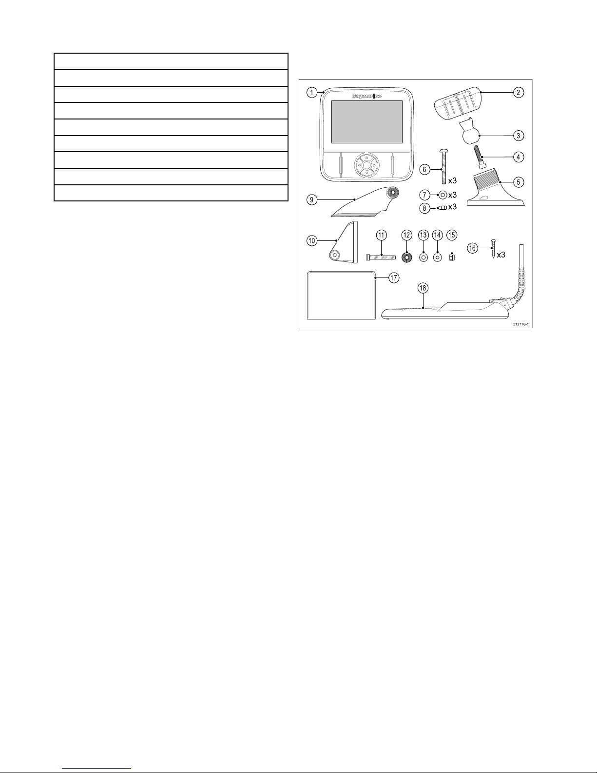
3.2Partssupplied–DV ,DVS,andPro
variants
Thepartssuppliedwithyourproductareshown
below.
D13178-1
1
9
10
16
6
7
8
2
3
4
5
17
x3
x3
x3
x3
111812 13 14 15
1.Displayunit
2.Lockingcollar
3.Pivotball
4.M6Hexbolt
5.Displaybracketbase
6.3xM5pozi-drivebolt
7.3xM5washer
8.3xM5lockingnut
9.Ratchetarm
10.Mountingbracket
11.M5Hexratchetbolt
12.Ratchetplate
13.Compressionwasher
14.M5washer
15.M5lockingnut
16.3xSelftappingscrews
17.Documentation
18.Transducerwithcombinedpowercable
20
Dragony–4/Dragony–5/Dragony–7/Wi–Fish
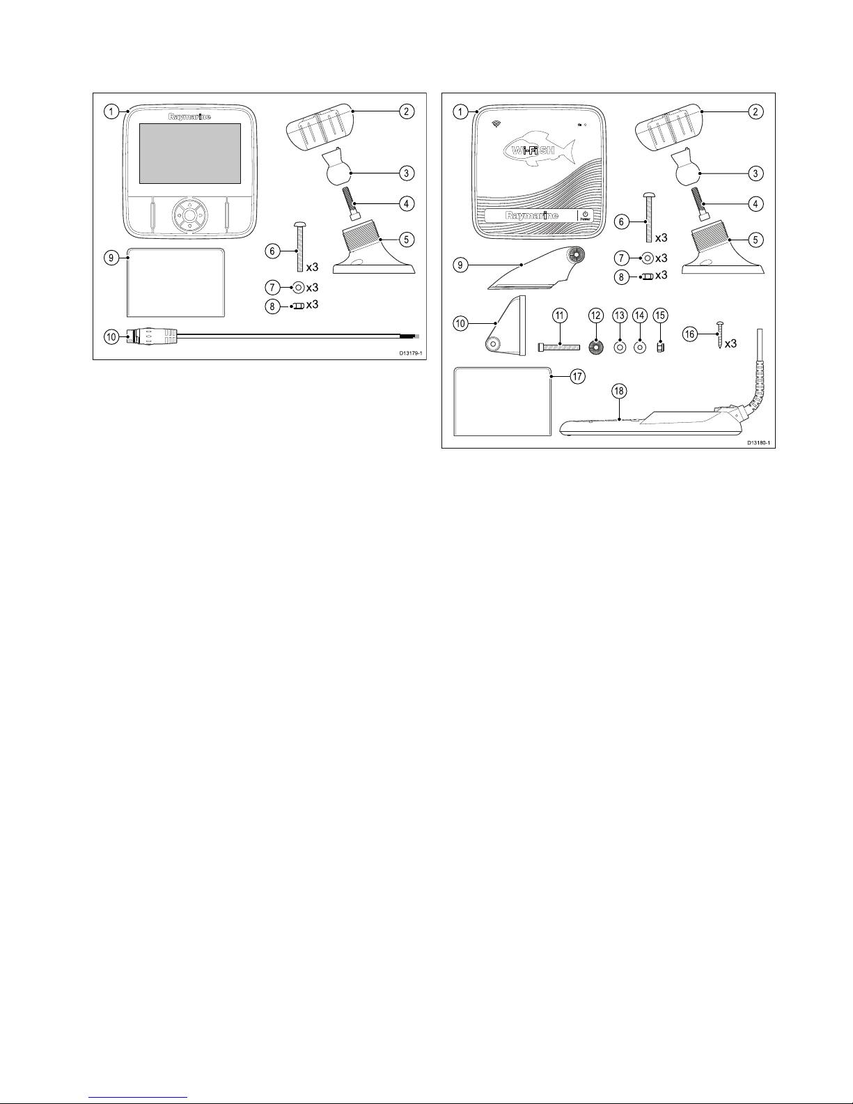
3.3Partssupplied–5M
Thepartssuppliedwithyourproductareshown
below.
D13179-1
1
9
10
6
7
8
2
3
4
5
x3
x3
x3
1.Displayunit
2.Lockingcollar
3.Pivotball
4.M6Hexbolt
5.Displaybracketbase
6.3xM5pozi-drivebolt
7.3xM5washer
8.3xM5lockingnut
9.Documentation
10.1.5m(4.9ft.)Powercable
3.4Partssupplied—Wi-Fish
™
Thepartssuppliedwithyourproductareshown
below.
D13180-1
1
9
10
16
6
7
8
2
3
4
5
17
x3
x3
x3
x3
111812 13 14 15
1.Wi-Fish
™
unit
2.Lockingcollar
3.Pivotball
4.M6Hexbolt
5.Unitbracketbase
6.3xM5pozi-drivebolt
7.3xM5washer
8.3xM5lockingnut
9.Ratchetarm
10.Mountingbracket
11.M5Hexratchetbolt
12.Ratchetplate
13.Compressionwasher
14.M5washer
15.M5lockingnut
16.3xSelftappingscrews
17.Documentation
18.Transducerwithcombinedpowercable
Planningtheinstallation
21
3.5DownVision
™
transducer
compatibility
TransducerDescription
Compatible
displays
CPT-DV(R70373)Singlebeam
DownVision
™
transducer(3
keywayconnector)
•DV
•Wi-Fish
™
CPT-DVS
(R70374)
Dualbeam
DownVision
™
andSonar
transducer(3
keywayconnector)
•DVS
•Pro
•Updated
Dragony6
•Updated
Dragony7
•*Legacy
Dragony6
•*LegacyDragony7
•Updated
CPT-60
(A80195)
•Updated
CPT-70
(A80278)
•Updated
CPT-80
(A80279)
Dualbeam
DownVision
™
andSonar
transducer(3
keywayconnector)
•DVS
•Pro
•Updated
Dragony6
•Updated
Dragony7
•*Legacy
Dragony6
•*LegacyDragony7
•LegacyCPT-60
(A80195)
•LegacyCPT-70
(A80278)
•LegacyCPT-80
(A80279)
Dualbeam
DownVision
™
andSonar
transducer(1
keywayconnector)
•Legacy
Dragony6
•LegacyDragony7
•*DVS
•*Pro
Note:*Adaptorcablerequiredforconnection.
Note:
•ConnectingaCPT-DVtoaDVSoraProwill
preventtheSonarapplicationfromfunctioning.
•ConnectingaCPT-DVStoaDVoraor
Wi-Fish
™
willnotenabletheSonarapplication.
•TheMcannotbeconnectedtoatransducer.
Legacyandupdatedproducts
Dragony6,Dragony7displaysandCPT-60
/CPT-70/CPT-80transducerdesignshave
beenmodiedtoincludetheimproved3keyway
connectors.
Thetablebelowidentiestheeffectivemanufacturing
datefortheimprovedkeywayconnectors.
Product
3keyway
introductiondate
3keyway
introduction
serialnumber
Dragony6
(E70085)
January2015E700850150001
Dragony7
(E70231)
November2014E702311140712
CPT-60(A80195)
December2014A801951240023
CPT-70(A80278)
January2015A802780150001
CPT-80(A80279)
January2015A802790150001
22
Dragony–4/Dragony–5/Dragony–7/Wi–Fish

3.6Toolsrequiredforinstallation—
Dragony
®
DV/DVS/Pro/Wi-Fish
™
1 3
5
2
4
6
D13176-1
1.Cordlessdrill
2.Pozi-drivescrewdriver
3.8mmwrench(spanner)
4.5mmHexwrench(allenkey)
5.4mmHexwrench(allenkey)
6.Drillbit
Youwillalsorequire:
•marinegradesealant
•awaterprooffuseholderand5Ainlinefuse.
•apaperclip(incaseyouneedtoremovethe
transducerfromthebracket.)
3.7Toolsrequiredforinstallation—
Dragony-5M
1 3
2
4 5
D13177-1
1.Cordlessdrill
2.Pozi-drivescrewdriver
3.8mmwrench(spanner)
4.5mmHexwrench(allenkey)
5.Drillbit
Youwillalsorequire:
•awaterprooffuseholderand5Ainlinefuse.
Planningtheinstallation
23

3.8Softwareupdates
Thesoftwarerunningontheproductcanbeupdated.
•Raymarineperiodicallyreleasessoftwareupdates
toimproveproductperformanceandaddnew
features.
•Youcanupdatethesoftwareforyourproductusing
aconnectedandcompatiblemultifunctiondisplay.
•Ifindoubtastothecorrectprocedureforupdating
yourproductsoftware,refertoyourdealeror
Raymarinetechnicalsupport.
Caution:Installingsoftware
updates
Thesoftwareupdateprocessiscarried
outatyourownrisk.Beforeinitiatingthe
updateprocessensureyouhavebacked
upanyimportantles.
Ensurethattheunithasareliablepower
supplyandthattheupdateprocessisnot
interrupted.
Damagecausedbyincompleteupdates
arenotcoveredbyRaymarinewarranty.
Bydownloadingthesoftwareupdate
package,youagreetotheseterms.
3.9Warningsandcautions
Important:Beforeproceeding,ensurethatyou
havereadandunderstoodthewarningsand
cautionsprovidedintheChapter1Important
informationsectionofthisdocument.
24
Dragony–4/Dragony–5/Dragony–7/Wi–Fish
3.10Selectingalocationforthe
transducer
Thisproductissuppliedwithatransommount
transducer.Theguidelinesbelowshouldbefollowed
whenselectingalocationforthetransducer.
Note:Thetransducerisnotsuitableformounting
onvesselswherethetransomisaftofthe
propeller(s).
Forbestperformancethetransducermustbe
installedinalocationwiththeleastturbulenceand
aeration.Themosteffectivewaytodeterminethis
isbycheckingthewaterowaroundthetransom
whilstunderway.
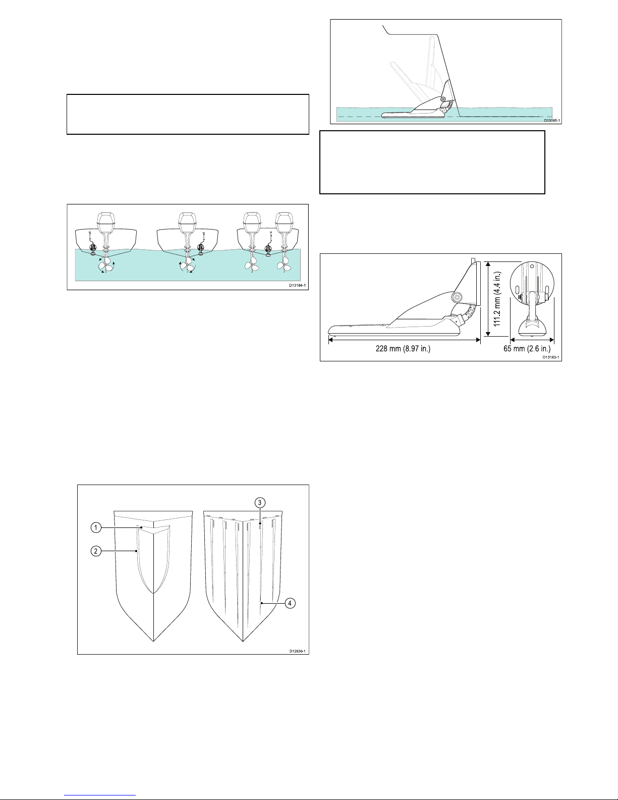
D13184-1
•Mountclosetothekeel(centerline),inaposition
wherethetransducerelementwillbefully
submergedwhenthevesselisplaningandturning.
•Mountasuitabledistancefromthepropeller(s)to
avoidwake.
•Forclockwiserotatingpropellers,mount
thetransduceronthestarboardside,for
counter-clockwise,mountontheportside.
•Onatwinenginevesselmountthetransducer
betweentheengines.
•Turbulencecanbecausedbyanumberofother
factorssuchassteps(1),ribs(2),rowsofrivets
(3)andstrakes(4).Theturbulenceappearsaft
oftheselocations.
1
2
4
3
D1263 6-1
•Airtrappedunderthefrontofthevesselcantravel
underthehullandappearasaerationaft.
•Ifinstallingonthestepofasteppedtransom,
allowsufcientroomabovethetransducerfor
transducerkickup.
D13185-1
Note:Optimumtransducerlocationwill
varydependingonvesseltype.Optimum
transducerheightandangleshouldbe
obtainedbytestingthetransducerwiththe
vesselinthewater.
Productdimensions–CPT-DVandCPT-DVS
Thetransducer’sdimensionsincludingthetransom
mountingbracketareshownbelow.
D13183-1
65 mm (2.6 in.)228 mm (8.97 in.)
111.2 mm (4.4 in.)
•TheCPT-DVcablelengthis4m(13.1ft.)
•TheCPT-DVScablelengthis6m(19.7ft.)
Planningtheinstallation
25

3.11Cablerouting
Cableroutingrequirementsforthetransducercable.
Important:T oavoidinterference,thecablemust
beroutedasfarawayfromVHFradioantenna
cablesaspossible.
•Checkthatthecableislongenoughtoreachthe
equipmentitwillbeconnectedto.Anoptional4m
(13.1ft)extensioncableisavailableifrequired.
•Ensurethereisenoughslackinthetransducer
cable,atthetransducerend,toallowthe
transducertopivotupanddown.
•Securethecableatregularintervalsusingcable
clips(notsupplied).
•Anyexcesscableshouldbecoiledupata
convenientlocation.
3.12Selectingalocationforthe
display
Generallocationrequirements
Whenselectingalocationfortheunititisimportant
toconsideranumberoffactors.
Ventilationrequirements
Toprovideadequateairow:
•Ensurethatequipmentismountedina
compartmentofsuitablesize.
•Ensurethatventilationholesarenotobstructed.
•Ensureadequateseparationofequipment.
Mountingsurfacerequirements
Ensureunitsareadequatelysupportedonasecure
surface.DoNOTmountunitsorcutholesinplaces
whichmaydamagethestructureofthevessel.
Cableroutingrequirements
Ensuretheunitismountedinalocationwhichallows
properroutingandconnectionofcables:
•Minimumcablebendradiusof100mm(3.94in)is
requiredunlessotherwisestated.
•Usecablesupportstopreventstresson
connectors.
Electricalinterference
Selectalocationthatisfarenoughawayfrom
devicesthatmaycauseinterference,suchas
motors,generatorsandradiotransmitters/receivers.
GPSlocationrequirements
Inadditiontogeneralguidelinesconcerningthe
locationofmarineelectronics,thereareanumber
ofenvironmentalfactorstoconsiderwheninstalling
equipmentwithaninternalGPSantenna.
Mountinglocation
•AboveDecksmounting:
Itisrecommendedthatthedisplayismounted
abovedecksasthisprovidesoptimalGPS
performance.
•BelowDecksmounting:
GPSperformancemaybelesseffectivewhen
mountedbelowdecks.
Vesselconstruction
Theconstructionofyourvesselcanhaveanimpact
onGPSperformance.Forexample,theproximity
ofheavystructuressuchasastructuralbulkhead,
ortheinterioroflargervesselsmayresultina
reducedGPSsignal.Beforelocatingequipment
withaninternalGPSantennabelowdecks,seek
professionalassistance.
Prevailingconditions
Theweatherandlocationofthevesselcanaffectthe
GPSperformance.Typicallycalmclearconditions
provideforamoreaccurateGPSx.Vesselsat
extremenortherlyorsoutherlylatitudesmayalso
26
Dragony–4/Dragony–5/Dragony–7/Wi–Fish
receiveaweakerGPSsignal.GPSantennamounted
belowdeckswillbemoresusceptibletoperformance
issuesrelatedtotheprevailingconditions.
Compasssafedistance
Topreventpotentialinterferencewiththevessel's
magneticcompasses,ensureanadequatedistance
ismaintainedfromthedisplay .
Whenchoosingasuitablelocationforthedisplay
youshouldaimtomaintainthemaximumpossible
distancebetweenthedisplayandanycompasses.
Typicallythisdistanceshouldbeatleast1m(3ft)
inalldirections.Howeverforsomesmallervessels
itmaynotbepossibletolocatethedisplaythisfar
awayfromacompass.Inthissituation,thefollowing
guresprovidetheminimumsafedistancethat
shouldbemaintainedbetweenthedisplayandany
compasses.
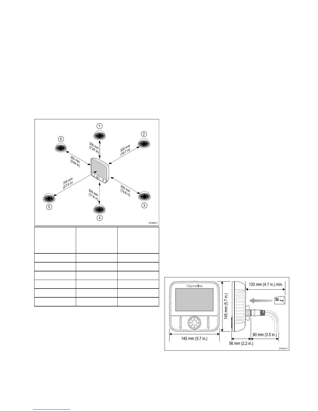
D1265 0-1
2
0
0
m
m
(
7
.
8
7
i
n
)
3
5
0
m
m
(
1
3
.
8
i
n
)
7
0
0
m
m
(
2
7
.
5
i
n
)
5
0
0
m
m
(
1
9
.
7
i
n
)
2
5
0
m
m
(
9
.8
4
i
n
)
00
0
1
2
3
3
0
0
m
m
(
1
1
.
8
i
n
)
4
5
6
Item
Compass
positionin
relationto
display
Minimumsafe
distancefrom
display
1Top
200mm(7.87in.)
2Rear
500mm(19.7in.)
3Right-handside
350mm(13.8in.)
4Underside
300mm(11.8in.)
5
Front
700mm(27.5in.)
6
Left-handside250mm(9.84in.)
Viewingangleconsiderations
Asdisplaycontrastandcolorareaffectedbythe
viewingangle,Ifyouintendtosurfacemountthe
display,itisrecommendedthatyoutemporarily
powerupthedisplaywhenplanningtheinstallation,
toenableyoutoidentifywhichlocationgivesthe
optimumviewingangle.
Wi-Filocationrequirements
AnumberoffactorscaninuenceWi-Fi
performance,itisimportanttoensureyoutestthe
Wi-Fiperformance,atthedesiredlocationbefore
installingWi-Fienabledproducts.
Distanceandsignalstrength
ThedistancebetweenWi-Fiproductsshouldalways
bekepttoaminimum.Donotexceedthemaximum
statedrangeofyourWi-Fiproduct(Maximumrange
willvaryforeachdevice).
Wi-Fiperformancedegradesoverdistanceso
productsfartherawaywillreceivelessnetwork
bandwidth.Productsinstalledclosetotheir
maximumWi-Firangemayexperienceslow
connectionspeeds,signaldropoutsornotbeing
abletoconnectatall.
Lineofsightandobstacles
ForbestresultstheWi-Fiproductshouldhavea
clear,directlineofsighttotheproductitwillbe
connectedto.Anyphysicalobstructionscandegrade
orevenblocktheWi-Fisignal.
Theconstructionofyourvesselcanalsohavean
impactonWi-Fiperformance.Forexample,metal
structuralbulkheadsandroongwillreduceandin
certainsituations,blocktheWi-Fisignal.
IftheWi-Fisignalpassesthroughabulkhead
containingpowercablesthiscanalsodegradeWi-Fi
performance.
Reectivesurfacessuchasmetalsurfaces,some
typesofglassandevenmirrorscandrasticallyeffect
performanceorevenblocktheWi-Fisignal.
interferenceandotherequipment
Wi-Fiproductsshouldbeinstalledatleast1m(3ft)
awayfrom:
•otherWi-Fienabledproducts
•transmittingproductsthatsendwirelesssignalsin
thesamefrequencyrange
•otherelectrical,electronicorelectromagnetic
equipmentthatmaygenerateinterference
InterferencefromotherpeoplesWi-Fiproductscan
alsocauseinterferencewithyourproducts.Y oucan
useaWi-FianalyzertooltoassessthebestWi-Fi
channel(channelnotinuseorusedbyleastamount
ofdevices)foryoutouse.
Productdimensions–Dragony–4and
Dragony–5
145 mm (5.7 in.)
145 mm (5.7 in.)
56 mm (2.2 in.)
90 mm (3.5 in.)
120 mm (4.7 in.) min.
D13181-1
Carepoints:
•Forvariantswithbuilt-inGPS,installinalocation
wheretheGPSperformancewillnotbeaffected
byvesselstructure;testGPSperformancebefore
installation.
•Allowaminimumof120mm(4.7in.)behindthe
displayforinsertingandremovingaMicroSDcard.
Planningtheinstallation
27
•Allowenoughroomfordisplayangleadjustment.
•Allowenoughheadroomtoremovethedisplay
fromthebracket.
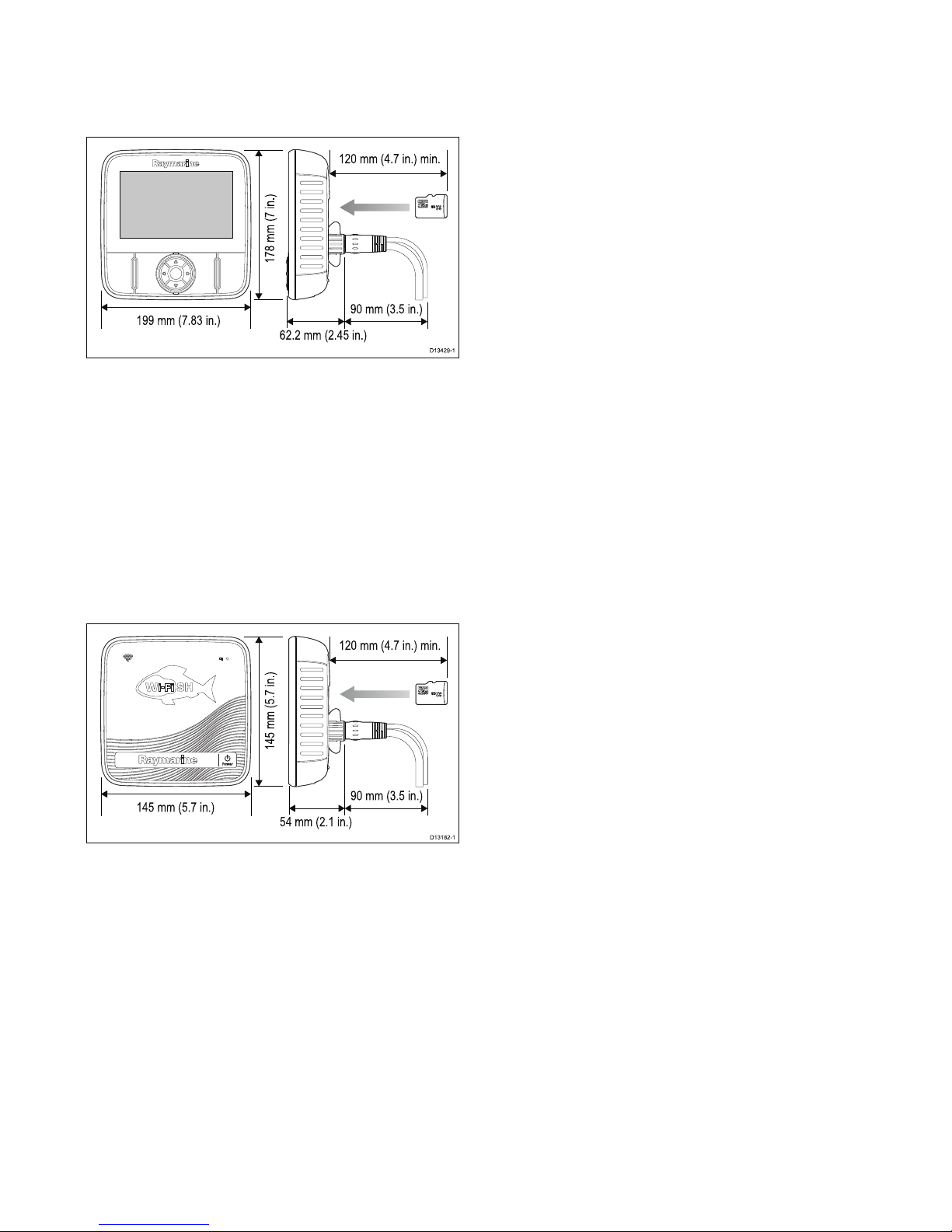
Productdimensions–Dragony–7
199 mm (7.83 in.)
178 mm (7 in.)
62.2 mm (2.45 in.)
90 mm (3.5 in.)
120 mm (4.7 in.) min.
D13429-1
Carepoints:
•Forvariantswithbuilt-inGPS,installinalocation
wheretheGPSperformancewillnotbeaffected
byvesselstructure;testGPSperformancebefore
installation.
•Allowaminimumof120mm(4.7in.)behindthe
displayforinsertingandremovingaMicroSDcard.
•Allowenoughroomfordisplayangleadjustment.
•Allowenoughheadroomtoremovethedisplay
fromthebracket.
Productdimensions—Wi-Fish
™
145 mm (5.7 in.)
145 mm (5.7 in.)
54 mm (2.1 in.)
90 mm (3.5 in.)
120 mm (4.7 in.) min.
D13182-1
Carepoints:
•Allowofminimumof120mm(4.7in.)behindthe
unitforinsertingandremovinganMicroSDcard.
•Allowenoughroomforunitangleadjustment.
•Allowenoughheadroomtoremovetheunitfrom
thebracket.
3.13Installationprocess
Thestepslistedbelowarerequiredtosuccessfully
installyourproductandensureoptimum
performance.
1.Mountingthetransducer.
2.Mountingthedisplay.
3.T estingthetransducer.
4.Finishingthetransducermounting.
28
Dragony–4/Dragony–5/Dragony–7/Wi–Fish

Chapter4:Mounting
Chaptercontents
•4.1Mountingthetransommountbracketonpage30
•4.2Mountingthetransduceronpage30
•4.3Mountingtheunitonpage31
•4.4T estingandadjustingthetransduceronpage32
•4.5Finalizingthetransducermountingonpage33
Mounting
29
4.1Mountingthetransommount
bracket
Thetransducermustbemountedonthetransom
usingthemountingbracketprovided.Thesteps
belowdescribetheinitialmountingstepsrequired
inordertotestyourtransducersperformance.
Aftertestingthetransduceryoumustnishthe
mountingfollowingtheinstructionsintheFinishing
thetransducermountingsection.
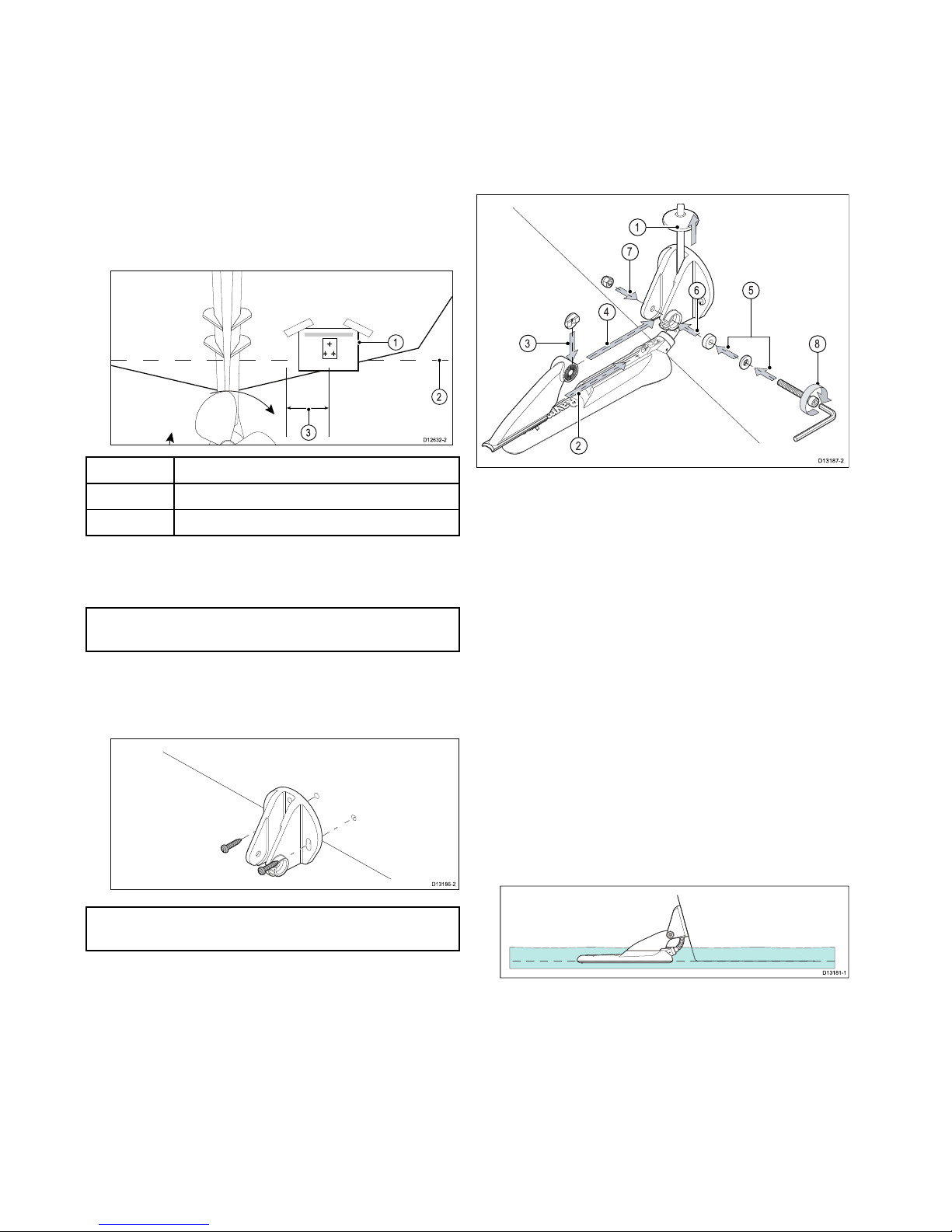
1.Fixthetransducermountingtemplatetothe
selectedlocation,usingmaskingorself-adhesive
tape.
1
2
3
D12632-2
1Transducermountingtemplate
2Waterline
3
Mountingawayfrompropeller
2.Ensurethetemplateisparalleltothewaterline.
3.Drill2xholesfortheadjustmentslotscrewsas
indicatedonthetemplate.
Note:DoNOTdrillthethirdmountingholeatthis
stage.
4.Fillthe2holeswithmarinegradesealant.
5.Usingapozi-drivescrewdriverandthescrews
provided,securethetransommountbracket
usingthe2adjustmentslots.
D13186-2
Note:Thethirdlockingscrewisnotuseduntilthe
transducerhasbeensuccessfullytested.
4.2Mountingthetransducer
Thetransducermustbemountedonthetransom
usingthemountingbracketprovided.Thesteps
belowdescribetheinitialmountingstepsrequired
inordertotestyourtransducersperformance.
Aftertestingthetransduceryoumustnishthe
mountingfollowingtheinstructionsintheFinishing
thetransducermountingsection.
D13187-2
2
1
3
6
8
7
4
5
1.Feedthetransducercablebetweenthepostson
themountingbracketasshown.
2.Slidetheratchetarmintotheguideonthetopof
thetransducer,ensuringitlocksinplace.
3.Holdtheratchetplateinplaceontheratchetarm
asshown.
4.Inserttheratchetarmbetweenthemounting
bracketposts,aligningthecenterholewiththe
holesintheposts.
5.SlidetheM5washerandthenthecompression
washerontotheratchetbolt.
6.Slidetheratchetboltthroughthemounting
bracketassembly.
7.InserttheM5lockingnutintothecaptivehousing
onthemountingbracket.
8.Usinga4mmHexwrench(allenkey)tighten
theratchetboltuntiltheratchetmechanismis
engagedbutcanstillbeadjustedbyhand.
9.Positionthetransducersothatthebottomfaceof
thetransducerwillbeparallelwiththewaterline
andtightentheratchetbolt.
D13181-1
Thetransducerpositionwillbeadjustedfurther
duringtesting.
30
Dragony–4/Dragony–5/Dragony–7/Wi–Fish
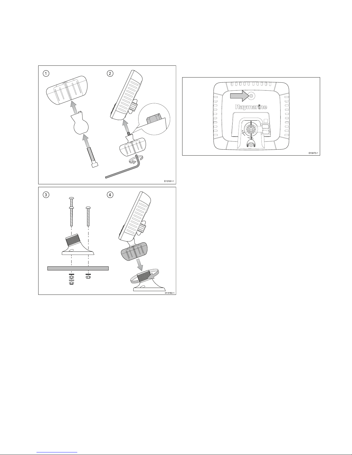
4.3Mountingtheunit
Theunitismountedusingthebracketprovided.
Beforemountingensurethatyouhave:
•selectedasuitablelocation.
•installedthetransducerandroutedthe
power/transducercabletotheselectedlocation.
1 2
D13191-1
3 4
D13192-1
1.SlidetheHex(allen)boltthroughthepivotball,
thenslidethepivotballthroughthecenterofthe
bracketlockingcollar.
2.Usinga5mmHex(allen)key(notsupplied),
screwtheHex(allen)boltintotheundersideof
theunit,ensuringthelocatingtabsarecorrectly
aligned.
3.Usingthexingsprovidedmountthebracket
basetothemountingsurfaceasfollows:
i.Markthelocationofthebracketbase’s
mountingholesonthechosenmounting
surface.
ii.Drillholesforthexingsusingasuitabledrill,
ensuringthereisnothingbehindthesurface
thatmaybedamaged.
iii.Useapozi-drivescrewdriverandan8mm
wrench(spanner)toattachthebracketbase
securelytothemountingsurfaceusingthe
xingsprovided.
4.Positiontheunitatthedesiredangleandsecure
bytighteningthelockingcollar.
Theunitcanberemovedfromthebracket,by
unscrewingthelockingcollar.
Dragony-7PromountingusingRAM
®
mounts
TheDragony-7Procanalsobebracketmounted
usingRAM
®
mountscompatiblewiththeRAM1”
Tough-Ball
™
withM6–1x6mmMalethreadedpost
(PartNumber:RAP-B-379U-M616).
D13472-1
ThethreadedpostcanbeattachedtotheM6captive
nut,locatedtopcenterontherearofthedisplay.
Mounting
31
4.4Testingandadjustingthe
transducer
Oncetheinitialmountingprocedureshavebeen
carriedout,thetransducermustbetestedpriorto
nishingthemounting.
Thetestingshouldbecarriedoutwithyourvessel
inthewater,withadepthgreaterthan0.7m(2.3
ft)butlessthanthemaximumdepthrangeofthe
transducer.
Important:TheSonarchannelwillbeableto
maintainreadingsathighervesselspeedsandat
greaterdepthsthantheDownVision
™
application.
1.PressandholdthePowerbuttontopowerthe
uniton.
2.CompletetheStart-upwizardandtutorial.
3.Opentherelevantapplication.
Thebottomshouldbevisibleonscreenanda
depthreadingdisplayed.
4.Startmovingyourvesselatalowspeed,ensuring
youhaveadepthreadingandaclearimageis
displayed.
5.Graduallyincreasethevesselspeedwhilst
checkingthedisplay ,iftheimagebecomespoor
orthebottomismissingatlowerspeedsthenthe
transducerneedstobeadjusted.
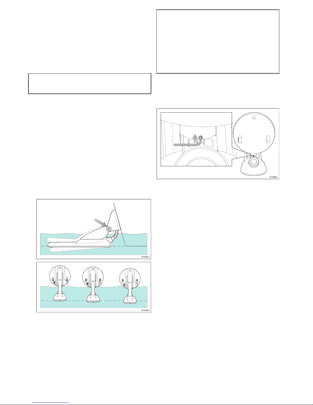
6.Angleandheightadjustmentsshouldbemadein
smallincrementsandre-testedeachtimeuntil
youobtainoptimumperformance.
D13195-1
D13196-1
7.Loosentheratchetarmbolttoadjustthe
transducerangle.
8.Loosenthe2mountingbracketscrewstoadjust
thetransducerheight.
9.Re-tightentheratchetarmboltandmounting
screwsbeforere-testing.
Note:
•Itmaynotalwaysbepossibletoobtaindepth
readingsathigherspeedsduetoairbubbles
passingunderthetransducer.
•Itmaybenecessarytomakeseveral
adjustmentstothetransducerbeforeobtaining
optimumperformance.
•Ifthetransducerrequiresrepositioningensure
alloldholesarelledwithmarinegradesealant.
Removingthetransducer
Thetransducercanbereleasedfromthebracketby
insertingasmallmetalrodsuchasapaperclipinto
thetransducerreleaseholelocatedasshown.
D13189-1
1.Insertthemetalrodintothetransducerrelease
hole.
2.Slidethetransduceroffofthebracket.
32
Dragony–4/Dragony–5/Dragony–7/Wi–Fish
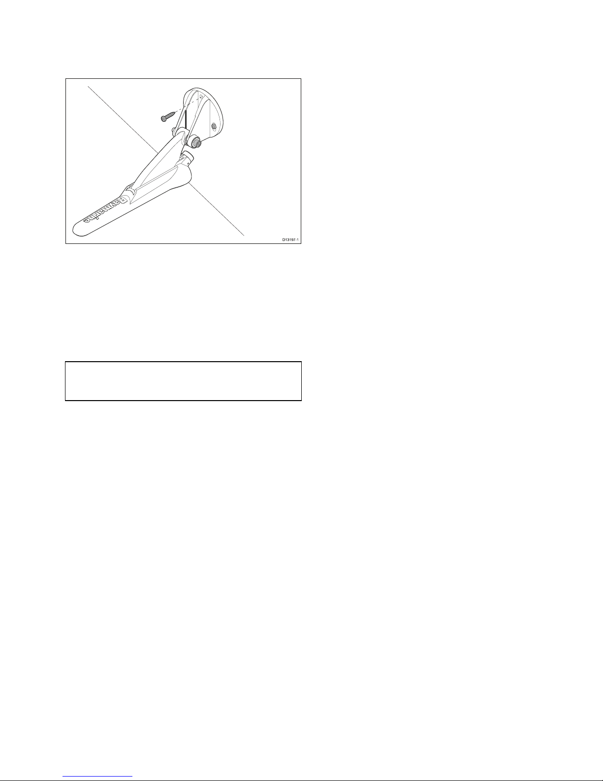
4.5Finalizingthetransducermounting
Onceyouhaveachievedoptimumperformanceat
thedesiredvesselspeedsthetransducermustbe
lockedintopositiontocompletetheinstallation.
D13197-1
1.Drillthelockingholelocationtakingcarenotto
damagethemountingbracket.
2.Fillthelockingholewithmarinegradesealant.
3.Securethetransducerandbracketbyfully
tighteningall3mountingscrews.
4.Securetheratchetarmbolt,bytighteninguntil
thecompressionwasheriscompressedandthen
addanother1/4turn.Ifthetransducerkicksupat
speedthentightenfurther.
Important:Takecaretoensurethatthepivotbolt
isnotovertightenedasthiswillpreventkick-up
andmaycausedamage.
Mounting
33

Chapter5:Cablesandconnections
Chaptercontents
•5.1Generalcablingguidanceonpage36
•5.2Connectionsoverviewonpage36
•5.3Cableconnection–DV,DVS,ProandWi-Fish
™
onpage38
•5.4Connectingthepowercable-5Monpage38
•5.5Extensioncableconnectiononpage41
Cablesandconnections35
5.1Generalcablingguidance
Cabletypesandlength
Itisimportanttousecablesoftheappropriatetype
andlength
•Unlessotherwisestateduseonlystandardcables
ofthecorrecttype,suppliedbyRaymarine.
•Ensurethatanynon-Raymarinecablesareofthe
correctqualityandgauge.Forexample,longer
powercablerunsmayrequirelargerwiregauges
tominimizevoltagedropalongtherun.
Routingcables
Cablesmustberoutedcorrectly,tomaximize
performanceandprolongcablelife.
•DoNOTbendcablesexcessively.Wherever
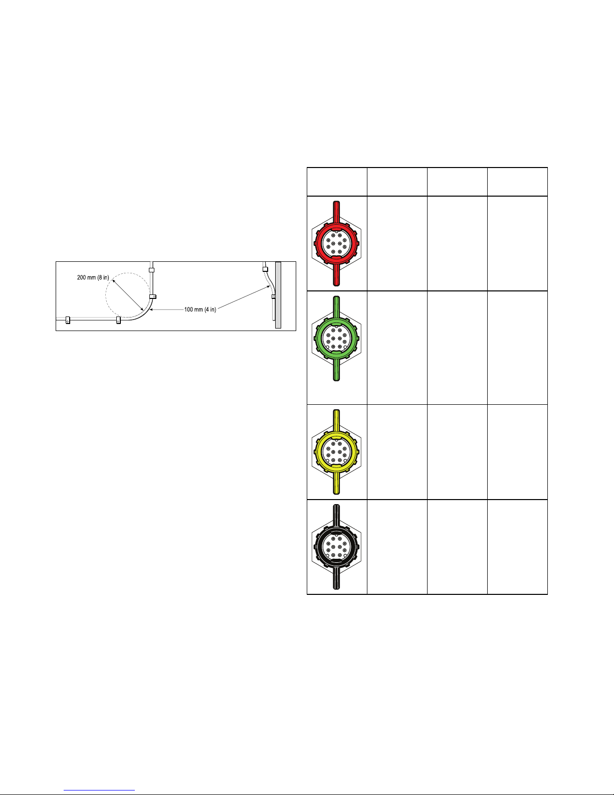
possible,ensureaminimumbenddiameterof200
mm(8in)/minimumbendradiusof100mm(4in).
100 mm (4 in)
200 mm (8 in)
•Protectallcablesfromphysicaldamageand
exposuretoheat.Usetrunkingorconduitwhere
possible.DoNOTruncablesthroughbilgesor
doorways,orclosetomovingorhotobjects.
•Securecablesinplaceusingtie-wrapsorlacing
twine.Coilanyextracableandtieitoutoftheway.
•Whereacablepassesthroughanexposed
bulkheadordeckhead,useasuitablewatertight
feed-through.
•DoNOTruncablesneartoenginesoruorescent
lights.
Alwaysroutedatacablesasfarawayaspossible
from:
•otherequipmentandcables,
•highcurrentcarryingACandDCpowerlines,
•antennae.
Strainrelief
Ensureadequatestrainreliefisprovided.Protect
connectorsfromstrainandensuretheywillnotpull
outunderextremeseaconditions.
Cableshielding
Ensurethatthecableisproperlyshieldedthatthe
cableshieldingisintact(e.g.hasn’tbeenscrapedoff
bybeingsqueezedthroughatightarea).
5.2Connectionsoverview
Dragony-4,Dragony-5,Dragony-7Pro,
Wi-Fish
™
productsandtheCPT-DVandCPT-DVS
includeconnectorswitha3keywayguide.
DependingondateofmanufactureDragony6,
Dragony7productsandCPT-60/CPT-70/CPT-80
transducersareavailablewith1keywayguide
(Legacy)or3keywayguide(Updated).Adaptor
cablescanbeusedtoconnect1keywayconnectors
to3keywayconnectors.
Rearconnector/Lockingcollar
ConnectorDescription
Unit/
Display
Compatible
transducer
Red–1
keyway
•Legacy
Dragony
6
•Legacy
Dragony
7
•Legacy
CPT-60
•Legacy
CPT-70
•Legacy
CPT-80
Green–3
keyway
•DVS
•Pro
•Updated
Dragony
6
•Updated
Dragony
7
•CPT-DVS
•Updated
CPT-60
•Updated
CPT-70
•Updated
CPT-80
Yellow–3
keyway
•DV
•Wi-Fish
™
•CPT-DV
Black–3
keyway
•5M
•N/A–5
Mpower
connector
36
Dragony–4/Dragony–5/Dragony–7/Wi–Fish
 Loading...