


|
www.radioshack.comSM |
Advance CID/Call Waiting ID Box |
||||
|
with Blue Backlight and 10-Number VIP |
|||||
|
|
|||||
OWNER’S MANUAL — |
|
|
|
43-3903 |
||
Please read before using this equipment. |
|
|
|
|||
|
|
|
|
|
|
|
Thank you for purchasing a RadioShack Advance |
The display is |
|
|
|
||
protected by a |
|
|
|
|||
CID/Call Waiting ID Box. Your Caller ID box stores and |
|
|
|
|||
piece of film |
|
|
|
|||
displays up to 64 Caller ID records. It displays the caller’s |
|
|
|
|||
during ship- |
|
|
|
|||
telephone number (and name, if available in your area) and |
|
|
|
|||
the current date and time, as provided by your local phone |
ment. Peel off |
|
|
|
||
this film before |
|
|
|
|||
company to Caller ID service subscribers. |
|
|
|
|||
you use the |
|
|
|
|||
|
|
|
|
|
||
Where Caller ID is offered, one or more of the following |
Caller ID box. |
|
|
|
||
options are generally available. ! |
Press to |
|
|
|
||
|
|
|
|
|
||
• |
caller’s number only |
delete Caller |
|
|
|
|
• |
caller’s name only |
ID records, or |
|
|
|
|
confirm |
|
|
|
|||
• |
caller’s name and number |
|
|
|
||
programmed |
|
|
|
|||
The actual number of Caller ID records your Caller ID box |
|
|
|
|||
information. |
Press to scroll |
Press to call |
NEW VIP |
|||
stores depends on the Caller ID information sent by the phone |
|
back a number |
||||
Press to save and |
through Caller ID |
Call Light |
||||
company. |
and program |
|||||
work with a list of |
records and program |
|
||||
|
|
callback |
|
|||
|
|
important callers. |
the Caller ID box. |
|
||
|
|
options. |
|
|||
|
|
|
|
|
||
! IMPORTANT !
To use this Caller ID box, you must be in an area where Caller ID service is available, and you must subscribe to the service.
ÔNOTE Ô
•The backlight does not work if the AC adapter is disconnected.
•The USOC number for both the single-line and two-line jacks to be installed is RJ11C (or RJ11W for a wall plate jack).
If your home has specially wired alarm equipment connected to the telephone line, be sure that installing the Caller ID box does not disable your alarm equipment. If you have questions about what will disable your alarm equipment, contact your telephone company or a qualified installer.
ÔBATTERY NOTES Ô
•Dispose of dead batteries promptly and properly.
•Do not burn or bury batteries.
•Use only fresh batteries of the required size and recommended type.
•Do not mix old and new batteries, different types of batteries (standard, alkaline, or rechargeable), or rechargeable batteries of different capacities.
•If you do not plan to use the Caller ID box for a month or more, remove the batteries. Batteries can leak chemicals that can destroy electronic parts.
•When replacing batteries, do not press any buttons on the Caller ID box after you remove the old batteries. Doing so could erase all stored information.
•When replacing the batteries, have fresh ones on hand before you begin. If you do not install the new batteries within about 2 minutes after removing the old ones, you will lose all the information stored in the
Caller ID box.
CALLER ID BOX SETUP
Caller ID is a service provided by your telephone company. When you subscribe to this service, between the first and second rings, the telephone company sends the caller’s telephone number (and name, if available) and the call’s date and time. The Caller ID box receives and displays this information for each call and updates the display with the current date and time. Your Caller ID box saves up to 64 Caller ID records, then replaces the oldest Caller ID record with each new one.
INSTALLING BATTERIES
You need four AA |
|
|
|
|
|
batteries (not |
|
|
|
|
|
supplied) to power |
|
|
|
|
|
and protect the |
|
|
|
|
- |
Caller ID box’s |
+ |
AA |
- |
+ |
AA |
+ |
|||||
memory during a |
|
AA |
+ |
- |
AA |
- |
|
|
|||
|
|
|
|||
|
|
|
|
|
power failure. Batteries are available at your local RadioShack store or online at
www.radioshack.com. Ô
1.While holding down the button on the bottom of the attached mounting bracket, lift up the bracket to remove it.
2.Use a flat-blade screwdriver to lift the tab on the battery compartment door on the bottom of the Caller ID box.
3.Place four fresh AA batteries (not supplied) into the compartment as indicated by the polarity symbols (+ and –) marked inside.
4.Replace the battery cover and snap it closed.
When 
 appears or the display dims, replace the batteries.
|
|
! IMPORTANT ! |
! — Important |
If an icon appears at the end of a paragraph, go to the box on that page with |
|
the corresponding icon for pertinent information. |
Ô — Note |
|
|
CONNECTING THE
AC ADAPTER
To power the system, plug the
!supplied Class 2 AC adapter’s barrel plug into DC 6V 200 mA on the
back of the Caller ID box. Then connect the other end of the adapter to a standard AC outlet. Ô
CALLER ID BOX CONNECTION
Your Caller ID box is ETL listed to UL standards and meets all applicable FCC requirements.
Your Caller ID box connects directly to a modular telephone line jack. If your telephone wiring does not have a modular jack, you can update the wiring yourself using jacks and adapters (available at your local RadioShack store), or have the telephone company update the wiring for you. You must use compatible modular jacks that are compliant with Part 68 of FCC Rules and the requirements adopted by the ACTA. The telephone cord and modular plug provided is Part 68 compliant for connecting to the telephone company network. Ô
Connecting to a Single-Line Phone
1.Disconnect the telephone line cord from the modular phone jack on the wall and plug it into the PHONE JACK on the back of the Caller ID box.
2.Plug the Caller ID box’s pre-wired telephone line cord into the modular phone jack on the wall.
© 2002 RadioShack Corporation.
All Rights Reserved.
RadioShack and RadioShack.com are trademarks used by RadioShack Corporation.
Connecting to an Answering Machine
Be sure to set your answering machine to answer after two or more rings, so the Caller ID box has time to record the call information.
 To Telephone
1.Plug the Caller ID box’s prewired telephone line cord into the modular wall jack.
1.Plug one end of another modular cord (not supplied) into PHONE JACK.
1.Plug the line cord’s other end into the answering machine’s line jack.
1.Plug one end of a third telephone line cord into the answering machine’s phone jack and the other end into the phone’s modular jack.
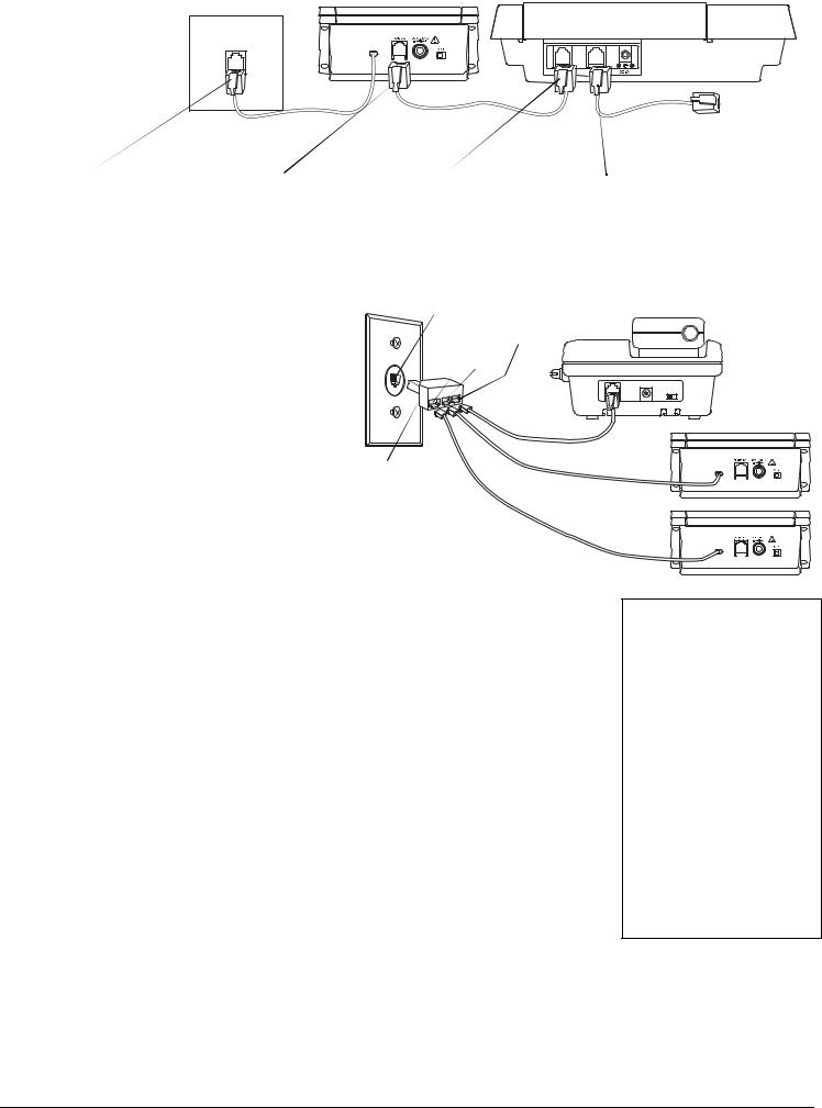
Connecting to a Two-Line Phone
To record information about calls received on a two-line phone, you can connect two Caller ID boxes using a triplex adapter (not supplied, available at RadioShack). Each Caller ID box only records information about calls received on the line to which it is connected.
Your modular phone wall jack must be an RJ14 jack wired for two phone lines.
1.Disconnect the telephone line cord from the modular phone wall jack, and plug it into the L1 + L2 jack on the triplex adapter.
2.Plug the triplex adapter into the modular phone wall jack.
3.Plug the pre-wired telephone line cord from your Caller ID box into either L1 or L2 on the triplex adapter.
4.Repeat Step 3 to connect another Caller ID box to the other available jack (L1 or L2) on the triplex adapter.
Modular Phone Wall Jack
L1 + L2
L1 L2
Triplex
Adapter
MOUNTING THE
CALLER ID BOX
You can set the Caller ID box flat on a desk, shelf or table by itself or with the supplied mounting bracket, or use the mounting bracket to mount the Caller ID box on a wall.
You need two screws (not supplied) with heads larger than the keyhole slots in the mounting bracket.
1.Using the keyholes in the bracket as a template, mark the mounting screw locations on the wall.
2.Drill a hole in the wall at each marked location.
3.Thread the screws into the holes, letting the heads extend about 1/8 inch (3mm) from the mounting surface.
4.Attach the mounting bracket to the Caller ID box.
5.Align the keyhole slots on the mounting bracket with the screws and slide the Caller ID box down until it is secure.
6.Lift the Caller ID box’s screen to adjust it to the desired angle.
2. |
Press REVIEW |
or |
to select the desired |
|
language. Press DELETE to confirm. LCD |
||
|
CONTRAST and 1 2 3 4 5 appear, and 3 flashes. |
||
3. |
Press REVIEW |
or |
to select the |
|
contrast level (from 1 – |
5). Press DELETE to |
|
|
confirm. ENTER AREA CODE, and _ _ _ appears, |
||
|
and the first _ flashes. |
|
|
4. |
Press REVIEW |
or |
to select the area |
|
code. Press DELETE to confirm the selection. |
||
5.Repeat Step 4 to set the second and third digit. Ô
6.M/S (master/secondary) on the back of the Caller ID box lets you connect up to four Caller ID boxes to the same phone line, so
you can receive Caller ID information on more than one phone on that line. Ô
If you are installing one Caller ID box, set M/S to M. If you are installing more than one Caller ID box, set M/S on one Caller ID box to M then set M/S to S on the other Caller ID boxes.
ÔNOTE Ô
•If no keys are pressed for 20 seconds, the Caller ID box exits setup.
•If you install more than one Caller ID box on the same phone line and do not set M/S on at least one Caller ID box to M, incoming calls might be disconnected.
•You can also connect other Caller ID modules that do not have the Call Waiting function to the same phone line as your Caller ID box, as long as you do not connect more than four modules at the same time (including this Caller ID box).
•If you connect another type of CID module (other than this Caller ID box) that has Call Waiting to the same phone line, the CID Waiting signal might be garbled or not received.
2
 Loading...