


AM-FM Stereo Cassette
OWNER’S MANUAL
Please read before using this equipment.
High-Power In-Dash
with Anti-Theft Detachable Faceplate
AM/FM Stereo Cassette
Cat. No. 12-2115
B
12-2115a.fm Page 1 Wednesday, January 12, 2000 11:18 AM

2
FEATURES
© 2000 T andy Corporation.
All Rights Reserved.
RadioShack is a registered trademark used by Tandy Corporation.
Your RadioShack High-Power In-Dash
AM/FM Stereo Cassette has many practi-
cal, easy-to-use features, and you can in-
stall it in almost any vehicle. The tuner’s
digital synthesized PLL (Phase-Locked
Loop) circuitry gives you precise tuning
and drift-free reception. The stereo’s anti-
theft control panel is easy to remove.
The auto-reverse cassette deck, memo-
ry tuning, and seek and scan tuning fea-
tures all help make your stereo’s
operation simple and quick to he lp you
drive safely.
Caution:
Use common sense. Do not
change your stereo’s settings in heavy
traffic or during hazardous driving condi-
tions.
This stereo’s features include:
Anti-Theft Control Panel
—
lets you
quickly remove and store the stereo’s
control panel in the supplied carrying
case. This discourages theft because the
stereo cannot operate without the control
panel.
High Power
— provides 80 watts of total
power to give you excellent audio re-
sponse for all types of music.
Auto-Reverse
—
continuously plays
both sides of a cassette tape.
Auto-Search Music System
—
auto-
matically searches for the beginning of
the previous or next track on the tape.
Dolby
B Noise Reduction
— assures
low noise music reproduction and a wide
dynamic range.
Manual/Automatic Memory Program-
ming
—
lets you manually or automati-
cally store 18 FM and 12 AM stations into
memory groups so you can quickly tune
to those stations.
Memory Scan Tuning
—
scans all sta-
tions in an AM or FM memory group,
playing each for 5 seconds.
Seek Tuning
—
searches forward or
backward to the next strong station in the
selected band. This makes finding a sta-
tion quick and easy.
RCA Line In Jacks
—
let you connect an
external portable CD player or a stand-
alone CD changer/controller system to
your stereo.
RCA Line Out Connectors
—
let you
connect an optional amplifier to your st e-
reo.
Metal
Tape Selector
—
takes advan-
tage of the improved sound quality of
metal tapes.
12-2115a.fm Page 2 Wednesday, January 12, 2000 11:18 AM

3
Lock-In Fast-Forward/Rewind
—
lets
you quickly move the tape forward or
backward.
Advanced FM Optimizer Circuitry
—
automatically adjusts the tuner’s high-
frequency response and stereo separa-
tion to give you the best possible sound,
regardless of the signal level.
Automatic FM Tuning Adjustment
—
automatically changes FM reception on
weak stations from stereo to mono, to
improve reception of those stations.
Lighted Liquid-Crystal Display with
Clock
—
lets you easily see the clock/
radio/cassette deck’s current functions.
Digitally Synthesized Circuitry
—
gives you precise tuning and drift-free re-
ception.
Mute
—
lets you silence or restore sound
with the push of a button.
Reset
—
lets you clear all stored sta-
tions.
Built-In Noise Suppression Choke
—
reduces the noise caused by your vehi-
cle’s electrical system.
12-2115a.fm Page 3 Wednesday, January 12, 2000 11:18 AM

4
CONTENTS
Installation ............................................................................................................... 5
Before You Begin the Installation ........................................................................ 5
Preparing the Mounting Area ....................................................................... 5
Routing Speaker Wires ................................................................................ 5
Using an Adapter Harness ........................................................................... 6
Making the Connections ..................................................................................... 6
Connecting Ground, Power, and Optional Components .............................. 8
Connecting Two Pairs of Speakers .............................................................. 9
Connecting One Pair of Speakers ............. ... ... .... ...................................... . 10
Connecting the Antenna ........................................................................ ... . 11
Completing the Connections ........................................ ... ........................... 11
Testing the Connections ................................................................................... 11
Removing the Shipping Screw .......................................................................... 11
Mounting the Stereo ......................................................................................... 12
Removing the Stereo from the Dash ................................................................ 14
Using the Control Panel ....................................................................................... 15
Replacing the Control Panel ............... ... ... .... ...................................... .... ... ... ... . 15
Removing the Control Panel ............................................................................. 15
Basic Operation ............ ... .... ...................................... .... ... ... ... ... ........................... 16
Setting the Clock ......................... .... ... ... ... ....................................... ... .... ... ... ... . 16
Adjusting the Controls ...................................................................................... 16
Using the Auxiliary Source Input ...................................................................... 17
Radio Operation .................................................................................................... 18
Playing the Radio ............................................................................................. 18
Memory Tuning ................................................................................................. 19
Manually Storing Stations ............................ ....................................... ... ... . 19
Automatically Storing Stations ............................................................ ... ... . 19
Selecting a Stored Station ......................................................................... 20
Scanning Stored Stations ...................................... ... ... .............................. 20
Cassette Player Operation .................................. ... ... .... ... ... ... ... .... ....................... 21
Playing a Cassette ............................................................................................ 21
Fast-Forward and Rewind ................................................................................. 22
Auto-Search Music System .............................................................................. 22
Care and Maintenance .......................................................................................... 23
The FCC Wants You to Know ........................................................................... 23
Cleaning the Tape-Handling Parts .................................................................... 24
Restoring Tape Tension and Sound Quality ...................................................... 24
Replacing a Fuse ................ ... ... ... ....................................... ... .... ... .................... 24
Specifications .......................... .......................... ...................... ....................... ....... 26
12-2115a.fm Page 4 Wednesday, January 12, 2000 11:18 AM

5
INSTALLATION
BEFORE YOU BEGIN THE
INSTALLATION
Before you install your stereo, read all
the instructions in this owner’s manual.
You should be able to answer these
questions about your vehicle’s electrical
system:
• Which terminal in the vehicle’s fuse
box supplies power even when the
ignition is off?
• Which terminal in the vehicle’s fuse
box is for accessories?
• How do I connect a wire to the fuse
box?
Also, be aware that installation in your
vehicle might require cutting or modifying
your vehicle.
Place the stereo as close as possible to
the selected mounting location. We rec-
ommend that you install the stereo by
temporarily connecting it to ground and
power, optional components, and your
speakers. Then test the connections,
disconnect the stereo, mount it in your
vehicle, and reconnect it. The instruc-
tions in this manual are arranged in this
order.
Cautions:
• For added safety and to protect your
stereo, disconnect the cable from
your vehicle’s negative (–) battery
terminal before you begin .
• Be sure your speakers can handle
20 watts of power output per chan-
nel. Each speaker must have an
impedance of at least 4 ohms. Your
local RadioShack store carries a full
line of speakers.
Preparing the Mounting Area
Before you mount the stereo, make sure
you have all the necessary materials.
Then confirm that the stereo f its your ve-
hicle’s mounting area. This stereo is a
DIN-E size unit that requires a 2
1
/
16
-inch
high by 7
3
/
16
-inch wide by 6
11
/
16
-inch
deep (53
×
182
×
170 mm) mounting ar-
ea.
Caution:
Be sure to avoid obstructions
behind the mounting surface.
Note:
If the mounting area is larger than
the stereo requires, you might be able to
mount the stereo with an in-dash installa-
tion kit, available at your local Ra-
dioShack store. Follow the installation
kit’s instructions to mount the stereo.
Routing Speaker Wires
If you install speakers, avoid routing the
speaker wires near moving parts or sharp
edges. You can usually route wires along
the wiring channel beneath the vehicle’s
door facings by carefully removing the
molding that holds the carpet in place. Af-
ter you route the wires, replace the mold-
ing.
12-2115a.fm Page 5 Wednesday, January 12, 2000 11:18 AM
6
Using an Adapter Harness
If you are replacing an existing stereo, or if your vehicle has been factory-wired
for autosound components, you can use an adapter harness to connect the power
and speakers. RadioShack stores sell adapter harnesses for most vehicles.
Follow the directions that come with the adapter harness to temporarily connect the
power and speakers.
After you connect the adapter harness to your vehicle, you can skip to “Testing the
Connections” on Page 11.
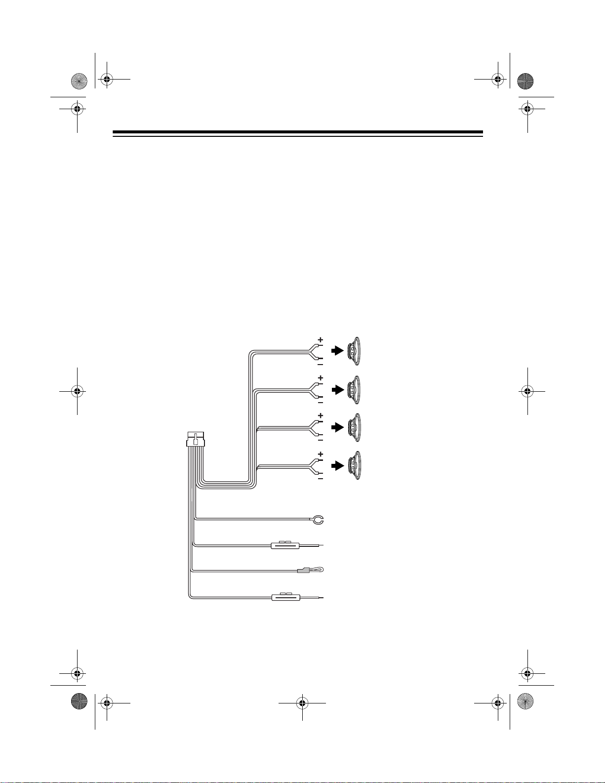
MAKING THE CONNECTIONS
Ground (–)
(To Chassis Ground)
+ 12V To Ignition
Amp Remote Turn On 500mA Max
(To Optional Equipment)
+ 12V To Battery
Front Left Speaker
Front Right Speaker
Rear Left Speaker
Rear Right Speaker
Black
Red
Blue/White
Yellow
Power
Wires
White
White/Black
Gray
Gray/Black
Green
Green/Black
Violet
Violet/Black
12-2115a.fm Page 6 Wednesday, January 12, 2000 11:18 AM

7
The supplied wiring harness with its 14-
pin connector includes all the lead wires
you need to connect the stereo to
ground, power, some optional compo-
nents, and speakers.
Important:
Do not cut these wires. If
you cut any wire, you cannot obtain a re-
fund or exchange on this product. Ra-
dioShack will provide warranty service if
you cut a wire and find the product is de-
fective.
You might need additional wire to com-
plete the connections, depending on
your individual auto sound system. Your
local RadioShack store carries a full line
of wire and wire management accesso-
ries.
Cautions:
•You
must
connect the GROUND,
+12V TO IGNITION, and +12V TO
BATTERY wires first, then make all other
connections as described in the fol-
lowing sections before you plug the
wiring harness into the stereo. If you
do not make the connections in the
order shown, an incorrect connection
could damage the stereo.
•You must connect a separate wire to
each speaker terminal as described
in “Connecting Two Pairs of Speak-
ers” on Page 9 or “Connecting One
Pair of Speakers” on Page 10. Do
not use a common wire or chassis
ground for any speaker connection.
12-2115a.fm Page 7 Wednesday, January 12, 2000 11:18 AM
8
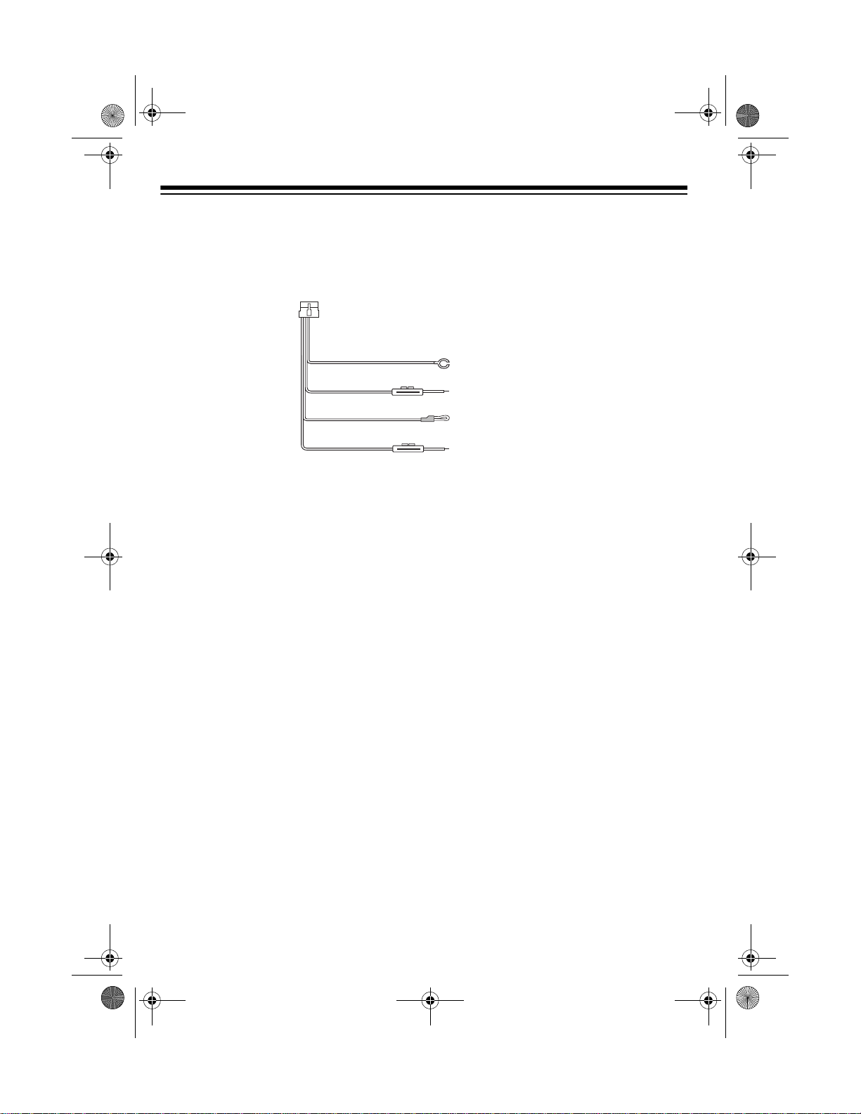
Connecting Ground, Power, and Optional Components
Follow these steps to connect the wiring harness to ground, power, clock memory,
and optional components.
Ground (–)
(To Chassis Ground)
+ 12V To Ignition
Amp Remote Turn On 500mA Max
(To Optional Equipment)
+12V To Battery
Power
Wires
Black
Red
Blue/White
Yellow
14-Pin
Connector
1.Disconnect the cable from your
vehicle’s negative (
–) battery termi-
nal.
2.Connect the black ground wire to a
chassis ground, such as a metal
screw attached to a metal part of
the vehicle’s frame. Be sure the
screw is not insulated from the
chassis by a plastic or rubber part.
3.
Connect the red +12V To Ignition wire
(with in-line fuse holder) to a point in
your vehicle’s fuse block that has
power only when you turn the vehi-
cle’s key to either the accessory
(ACC) or START position.
This connection turns on the stereo
when you turn on the ignition or turn
the key to ACC, and turns off the
stereo when you turn off the ignition.
This prevents your vehicle’s battery
from being drained if you leave the
stereo on when you turn off the igni-
tion.
4.Connect the yellow +12V To Battery
wire (with in-line fuse holder) to your
vehicle’s positive (+) battery termi-
nal or to a point in your vehicle’s
fuse block that provides a continu-
ous source of 12 volts. This connec-
tion provides power for the stereo’s
components (such as the clock),
and continuous power for the ste-
reo’s memory when the ignition is
off.
5.Connect the blue/white wire to any
optional equipment (designed to run
from a switched source) that you
want the stereo to turn on and off
(such as a remote amplifier or a
power antenna).
This wire does not provide power to
the components. It simply turns
them on or off. If you do not use this
wire, secure it with a wire tie and do
not let it touch metal.
Note:
To connect an optional amplifier.,
use the line out connectors on the back
of your car stereo and follow the instruc-
tions in the amplifier’s owner’s manual.
12-2115a.fm Page 8 Wednesday, January 12, 2000 11:18 AM
9
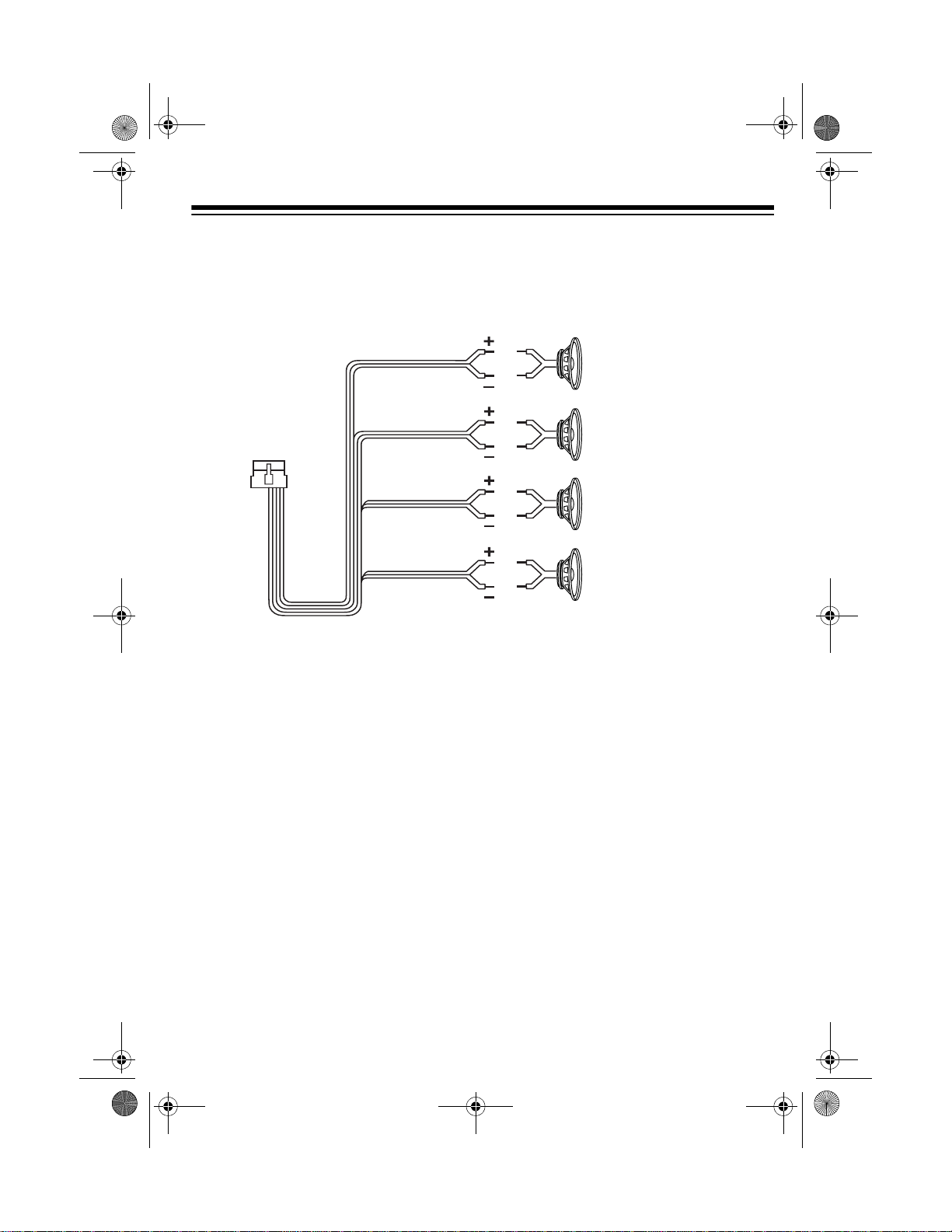
Connecting Two Pairs of Speakers
If you are using both front and rear speaker s, f ollo w these st eps t o co nne ct the wirin g
harness to the speakers.
1. Connect the gray wire to the right front speaker’s positive terminal. This terminal
is usually marked with a plus (+) sign or red mark.
2. Connect the gray/black wire to the right front speaker’s negative terminal. This
terminal might be marked with a minus (
–) sign or it might not be marked at all.
3. Connect the white wire to the left front speaker’s positive terminal.
4. Connect the white/black wire to the left front speaker’s negative terminal.
5. Connect the violet wire to the right rear speaker’s positive terminal.
6. Connect the violet/black wire to the right rear speaker’s negative terminal.
7. Connect the green wire to the left rear speaker’s positive terminal.
8. Connect the green/black wire to the left rear speaker’s negative terminal.
Front Left Speaker
Front Right Speaker
Rear Left Speaker
Rear Right Speaker
White
White/Black
Gray
Gray/Black
Green
Green/Black
Violet
Violet/Black
12-2115a.fm Page 9 Wednesday, January 12, 2000 11:18 AM
 Loading...