


I - DESCRIPTION
A. GENERAL DESCRIPTION
The Polaroid Land SX-70 is a folding, pocket sized, single-lens reflex camera which takes and immediately delivers full-color pictures approximately 31/4 inches square (see figures
1-1, 1-2 and 1-3). Operation is automatic; the user merely inserts the film, focuses and shoots. power is provided by a six-volt battery inside the film pack; therefore, the batteries are always fresh as the film.
The four element lens has a maximum aperture of f/8, and a focusing rang from 10,4 inches to infinity. The shutter is automatically controlled by a photocell and electronic timing. Electrical to mechanical energy conversion is accomplished by two solenoids and a motor. There are no separate diaphragm adjustement. The shutter opening and closing time is controlled by the exposure measuring system.
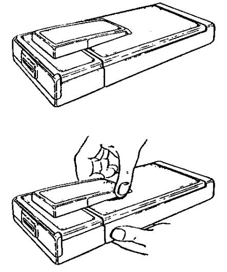
Figure 1-1 SX-70 Camera folded
Figure 1-2 Holding and opening the SX-70

Figure 1-3 Opened for picture taking
The subject is viewed and focused throught the taking lens, a mirror, a Fresnel viewing screen (with spilt-image focusing aid) and a optical system to focus the image at the viewing eyepiece. As in all single-lens reflex cameras, the shutter must be open to provide an image at the eye-piece. This requirement is fulfilled by the automatic electro-mechanical components which are described in detail in Section II of this manual.
When the exposure is made, the image must be transferredfromtheviewingsystemtothesurface of the film in accurate focus. To accomplish this, the shutter closes and the viewing screen swings out of the optical path which is then diverted by a mirror to the film surface. These two paths are described in greater detail elsewhere in this section.
The exposure is made following the viewing screen / mirror swing. The screen then returns to the viewing position and the automatic mechanism ejects the exposed sheet of film. development takes place outside the camera and can be observed by the operator.As soon as the print is ejected, the mechanism completes its
cycle to prepare for the next exposure. Following thenth exposure, the flash circuit is inhibited until a fresh film is inserted. Normal operation will resume when the camera is reloaded.
B. CAMERA OPERATION
The following paragraphs describe the electromechanicaleventsthatoccurinnormaloperation. the purpose of this desciption is to acquaint the reader with the manner in which the various functions are accomplished. Detailed analysis at component / sub assembly level appears in
Section II.
1. Opening the Camera
When the SX-70 is folded, an interlock switch
(S6) removes all battery power from the camera mechanism to prevent any drain from the film pack encapsulaetd batteries. To prepare the camera for picture taking, hold the camera in the left hand, pull straight up on the serrated portion of the viewfinder housing (Figure 1-2). this action releases latches, which, in turn, allow the main body of the camera to raise into operating position.
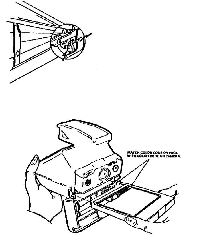
When the camera is fully opened, the interlock switch (S6), located at the left rear corner of the mirror cover, is closed and the battery is connected to the camera electrical circuit.
(Figure 1-4).
Figure 1-4 S6 with contacts closed
2. Loading the Film pack
The front coverlatchis located on the right side of the camera just inside the rim of the bottom cover assembly. Pressing down on this yellow latch releases the front cover which drops down to expose the film chamber. With the cover open, a film pack can be inserted or an exhausted pack can be removed.
A fresh film pack is loaded into the film chamber observing color coding (Figure 1-5). Under certain circunstances a partially used pack could be inserted, but this action will cause some deviation in the normal counting sequence.
The battery is a part of each film pack, and the two exposed terminals on the pack engage two contacts within the film chamber as the pack is inserted.
3. Starting the Automatic Mechanism
With the film pack in place, the front cover can be closed. It must be fully closed and latched.
Figure 1-5 Inserting film pack
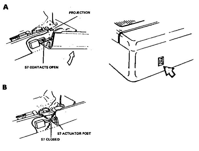
Gears in the front cover must engage the main gear train of the camera before the gear train is put into motion. A switch (S7) located in the forward section of the gear train compartment initiates the application of power to the gear train drive motor. Switch (S7) is actuated by two components
(1)A projection on the front cover latch
(Figure 1-6 A), and
(2)A post on the right rear edge of the front cover (Figure 1-6 B).
front edge of the front cover. The camera is now ready to take the first picture.
4. Setting the exposure counter
When a used film pack is removed from the film chamber, the action automatically resets the exposure counter at the rear of the camera to the start position, closing S8. With a new film pack installed and the front cover closed and latched (
S7 closed), the motor is powered, and the dark slide is ejected. The exposure counter turns to number 10 (Figure 1-7), indicating that 10 pictures remain in the pack.
Figure 1-6 S7 contacts open and closed
Thus, the cover must be fulled closed, the gears engaged, and the latch fully seated, in order to actuate the drive motor.
As S7 closes, power is applied to the drive motor (S8isalsoinvolvedandisdiscussedinafollowing paragraph), the gear train is set in motion and actuates a device called the film pick. The pick engages the dark slide, pushes it into the spread rolls and the dark slide is ejected from the lower
Figure 1-7 Counter
5. Viewing and focusing
Viewing and focusing is accomplished through a reflect system (Figure 1-8 A). In the viewing mode the image passes through the lens to a fixed mirror which reflects it down to the Fresnel viewing screen. The viewing path from the viewfinder eyepiece lens is from a parabolic mirror and wafer lens, off the fixed mirror to the
Fresnel screen. On most cameras the Fresnel screen contains a circular split-image aera which is used to focusing aid. A knurled knob (the focusing wheel) on the shutter housing is rotated to adjust the camera focus. The scene is in focus when a vertical line within the split-image aera is perfectly straight. On early cameras (without a split-image feature), the scene is in focus when the image seen on the Fresnel screen is sharpest.
6. Viewing and focusing
The exposure is made by pressing the release button. This completes the electrical circuit to the

Figure 1-8 Viewing and shooting
shutter to initiate a series of events. The shutter blades close to cut off the optical path. The hinged Fresnel viewing screen is swung upward and comes to rest in front of the fixed viewing mirror (Figure 1-8 B).
The shutter opens and closes to perform the exposure function.
A first-surfaced taking mirror is fastened to the underside of the Fresnel carrier assembly.
The image is reflected by the mirror onto the film surface. the electronic metering system determinesthe required exposure, and programs the shutter opening and duration accordingly.
The incorporation of a mirror in tghe lens-to-film path necessitated by the nature of the film. No separate negative film is employed. Instead, the image appears as a direct positive. Since the final product is an opaque print, it is viewed by reflection. As a result, the mirror is needed to reverse the image so that the final print will be properly oriented. This requirement, in turn, dictates the use of the reflectance type viewing screen rather than a ground-glass type transmission system.
Note that the film surface is deplaced from the Fresnel viewing screen by the thickness of the viewing screen assembly. The correct focal distance for both viewing and exposure is properly maintened, however, since the surfacecoated exposure mirror is deplaced by the same dimension.
During exposure, the light from the viewing system must be prevented from striking the film. This is accomplished by a rubber light stop adhered to the hinged Fresnel carrier. When the Fresnel carrier moves upward, the light stop blocks off light from the viewfinder eyepiece.
As indicated by the foregoing description, the viewing system is blacked out during the actual exposure.
As soon as the exposure is complete the mechanism returns the viewing screen to its initial position and the picks feeds the exposed film to the spreader rolls. The rolls break the pod, spread the developer, and eject the film from the camera.
7. Completing the film pack
As each exposure is completed, the exposure countersubstractsonedigituntilthe10exposures have be made. The counter then indicates 0...
When this occurs, switch S9 is closed. Closing this switch inhibits the flash and the exposure timing. Since the counting cycle is initiated by the insertion of a film pack, the pack may not necessary contain a full supply of film. If, for some reason, a partially used pack is removed and reinserted, the top film will be the dark
slide. The counter will start at number 10. Since switches S8 and S9 are physically attached to the counter, the camera will cycle through 10 exposures even though there be less than 10 sheets of film in the pack. This deviation must be recognized whenever a partially exposed pack is used.
8. Developing the print
As in orther Polaroid pack cameras, the picture is developed ouside the camera. Unlike previous
Polaroid Land Cameras, however, there is no negative to pell off and discard.
9. Exposures using flash
The SX-70 accepts a special 10-lamp flash bar that plugs into a receptacle directly over the camera lens. There are five lamps in a rowon either side of the bar which must be removed, rotated and reinserted after the fifth lamp has been fired (Figure 1-9).
Insering a flash into the flash socket closes switch S2 in the socket. This action sets up the shutter electronic circuit to permet firing of the flash lamp. A follow-focus mechanism, coupled to the lens focusing system arrests the shutter blades at an opening related to camera-to-suject distance.
NOTE : On early camera models, the light measuring circuit remains active even with the flash bar inserted into the socket. If the circuit determines that there sufficient ambient light, an exposurewillbemadewithouttheflash.Cameras with «P» configuration or later shutters, do not have this light measuring feature in the flash mode. Regardless of the ambient light level, the circuits will fire the flash when a flash bar is in the socket (unless of course, the lamps have all been used).
If the array has been exhausted, the shutter will complete the exposure cycle without flash.
Maximum exposure duration is 30 seconds.
When the exposure counter reaches 0 (empty) the camera will not fire a flash lamp even though unused lamps remain in the bar. The previously discusseddeviationassociatedwiththeexposure counter is applicable to the flash functions. If an unusedlamp is in position and if a partially empty film pack has been reinserted, the camera will continue to fire lamps after the last sheet of film has been exposed, until the counter reaches 0.

Figure 1-9 Inserting the flash bar
10. Closing the camera
When through using camera it be can folded and latched in its closed configuration by pushing the erecting link. When the camera is closed, the interlock switch (S6) is opened so that the batteryiscompletelydisconnectfromthecamera circuits. The trim wheel (the lighten / darken adjustement associated with the photocell) automatically returns to its normal position each time the camera is closed.
C. SHUTTER DESCRIPTION
(AMBIENT LIGHT MODE)
The shutter employed in the SX-70 camera is unique. No direct comparisons should be drawn between the manner in which it functions and the function of other Polaroid electronic shutters. No manuallyadjustableorfixedapertureisemployed.
When a picture is taken, two shutter blades, with
specially shaped cutouts, open the lens from a totally closed position to a suitable aperture. The two blades then reverse direction and again shut off the optical path. These same two blades also contain a similar (although differently shaped) pair of cutouts that open and close the light path to the photocell in like manner. In the following description the functions of photocell cutouts is deferred until the action of the shutter cutouts is explainedalthoughinoperation,thetwofunctions are interdependent.
When the camera is open for viewing, but before the release button is pressed, solenoid #1 is deenergized and the shutter blades are open. A spring (openong spring) holds the shutter blades wide open (Figure 1-10). The lens thus provides maximum viewing / focusing brilliance. Solenoid / spring action is discussed in detail in the next section of this manual.
Figure 1-10 Shutter blades held opened

When the release button is pressed, a switch
S1 closes (Figure 1-11 A and B) and applies operating power to the shutter.As soon as power is applied to the shutter, solenoid #1 is energized and rapidly moves the shutter blades to the closed position.
When the solenoid has reached the end of its stroke (shutter closed, it no longer requires maximum current to hold it at that postion.
Switch S4 (located on solenoid #1) closes (CB) and activates an electronic circuit called the
POWER DOWN CIRCUIT. This reduces power
Figure 1-11 A Location & Arrangement of internal parts
Figure 1-11 B Operation
to an adequate level to hold the solenoid after the high-current circuit has completed the solenoid operating function and switches on the motor drive circuit. Thus, the shutter will remain closed, with minimum battery drain.
Light entering the lens is now cut off and the reflex mirror is swung upward to picture-taking position. The electronic latch (activated by opening S5) assures that the sequence will be completed even if the operator removes his finger from the exposure button, S1.
When the mirror swings up, a mecchanically operated switch (S3) actuates a «Y» delay circuit (40 milliseconds) (Figure 1-12) so that the shutter will not function until the mirror bounce has subsided. At the end of the delay period the electronic circuitly removes the power from the soleniod and the opening spring sets the shutter blades in motion toward the full open position.
At the same instant an electronic switch opens and starts the integration cycle. The integration cycle is that period during which the total amount of light (intensity and duration) reaching the photocellistransformedelectronicallytoregulate the lenght of time the fiml is exposed. The shape of the opening in the shutter blades and the
motion of the blades is such that all of the factors involved are continously variable throughout the exposure period. this fact, however, is a design consideration and should not confuse the theory of the shutter operation from a maintenance point of view.
When the camera completes all off its automafed functions and the release button has been released, all voltage is removed from solenoid #1 and the shutter opens in preparation for the next exposure.
It should be noted that under extremeley low light conditions, the shutter will closed completing the exposure cycle in 14 to 30 seconds whether a suitable exposure has produced or not.
C. SHUTTER DESCRIPTION
(FLASH MODE)
The special ten-shot flash bar is equiped with a shorting bar so that when the bar is inserted, two contacts within the camera is shorted. This switch is identified as S2. When S2 is closed, the shutter electronic circuit detects that a flash bar is in place and ready for firing. In general, the sequence of the functions remains the same as for ambient light operation with the following exceptions :
Figure 1-12 S3 Being opened by recock ram

mechanical device identified as the interceptor connected to the lens focusing mecchanism
(Figure 1-13 A). the interceptor is moved as the lens is focused regardless of whether ambient-light or flash pictures are being taken.
When flash bar is in place (S2 closed) and the gear train opens switchs S5 (Fighure 1-14), solenoid #2 is energized and pulls the interceptor into position to phycally restrict the shutter blade travel (Figure 1-13 B). Since the interceptor is controlled by the focusing mechanism, the shutter opening is related to camera-to-subject distance thus compensating for the flashbulb-to- subject distance to give proper flash exposure. As a solenoid #1 de-energizes switch S4 moves from the CB position to the CA position. This switch conects VCC to the FFA.
When the flash delay period reaches completion, the circuitry removes the holding current from solenoid #2. Since the solenoid is an electromechanical device, removing power from it causesacollapsingmagneticfieldwhichinduces a fly back voltage. This voltage pulse is fed to the flash circuitry which then applies the firing voltage across the flash lamp.
Figure 1-13 A Interceptor link, Solenoid 2, S2 operation - Solenoid de-energized
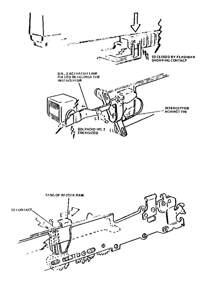
Figure 1-13 B Interceptor link, Solenoid 2, S2 operation - Solenoid energized
Figure 1-14 S5 being opened by the recock ram (Gear train)
In cameras with «P» configuration or later shutter there is no ambient light measurement made. If a flash bar is in the shutter socket a flash picture will result regardless of the ambient light level.
Onearlycameras,anambientlightmeasurement is made during the flash delay period. Since the photocell aperture is a part of the shutter blades, the amount of reflected light reaching the cell will alsobeafunctionoffocusingdistance.theshutter electronics delays firing the flash lamp until the shutter has opened to the aperture established by the focus wheel. during this delay period, if the ambient light level is sufficiently high to cause triggering of the integrating circuits, the exposure will be completed and the shutter closed before the firing voltage reaches the lamp and the lamp will not be fired.
At the ends of the flash timing interval, the circuit energizes solenoid #1, the shutter closes, and the sequence proceeds as in the ambient-light mode.
If the bulbs in the flash bar are all used when the operator attemps to make a flash exposure, all of the previously described circuitly will function up to the actual firing of the flash lamp. Since there is no lamp to ignite, no flash firing current will be drawn.
There will be no output signal from the flash sequencingcircuit,andanambientlightexposure will be made. On cameras with «P» or later configuration shutters, the result will be a black picture unless the ambient light level is high enough to give an exposure. this is caused by the fact that «P» and later configuration shutters have no integrating function as long as a flash bar is inserted in the socket. Early cameras have atwentysecondtime-outperiodevenwithaflash bar inserted in the socket. Therefore, if the flash bar is exhausted, a properly exposed picture will result if the ambient light is great enough to produce one in twenty seconds.

II - THEORY OF OPERATION
A. INTRODUCTION
A general description of the camera and the sequence of its functions is contained in
Section I. In that section, detailed analysis of individual assemblies and electrical circuits was minimized so that emphasis could be placed on the intenelation-ship of various functions. In the following paragraphs, the individual groups of components are described in greater detail. The description are presented in the sequence in the commponents were mentioned in Section I.
B. POWER SOURCE
Power for the drive motor, the shutter electronics, and the flash array is supplied by a specially designed 6 volts battery incorporated in each
10 exposures film pack. When the pack is inserted into the camera, two contacts pads on the bottom surface of the pack engage two spring-loaded contacts on the inner bottom surface of the camera bottom plate. From these two points, it is distributed to its destinations by the copper foil strips of a flex circuit on the outer surface of the bottom plate.
The battery has adequate capacity to expose all 10 film frames with at least six months of expected shelf life.
C. LENS
The lens employed is a four element, glass lens off/8aperturewithafocallenghtof115mm.Ithas a focusing range of infinity down to 10,4 inches. Focusing is accomplished by movement of the front element only. Helical threads in the lens mount provide the linear lens elemet movement.
Operation is by means of a geared focus wheel at the top of the shutter housing. There is no manualy adjustable diaphragm associated with the SX-70 lens.
D. VIEWING AND EXPOSING SYSTEM
When the camera is erected to picture taking configuration, the subject can be viewed through the collapsible viewfinder. Figures 2-1 and 2-2 show the two optical paths in the camera. Note the direction of the arrows. Reflected light from
Figure 2-1 Viewfinder optics (viewing)

Figure 2-2 Viewfinder optics (exposing)
the subject passes through the camera lens and is reflected by the viewing mirror (on the inside surfaceofthemirrorcover)totheFresnelviewing screen.
The entire subject image is now reproduced on the viewing screen. At this point, viewfinder optics must be employed for focusing. The optics must transfer the image from the viewing screen to the eye (done by the parabolic mirror and the viewing mirror) and must present the image in a fairly sharp contrast to permit proper focusing
(done by the eye lens and parabolic miror).
1. Fresnel (Figures 2-3 A and 2-3 B)
The special Fresnel (pronouced Freh-nell) screen is employed to enhance the viewing imagebyincreasingthebrightnessanddefintion. If a matte white surface were substituted for the
Fresnel screen, an image would still be visible.
However, the light rays striking nearest the corners of the screen meet the screen at a more oblique angle than the rays striking near the center. At this greater angle, a larger percentage of the light is dispersed and less light is returned to the viewer. Thus, on a matte-screen image the corners would appear darken than the center. The Fresnel screen is designed to overcome this problem.

The screen itself is a sheet of plastic upon which areimpressedseriesofconcentricringsmuchlike the grooves pressed into a phonograph record
(Figure 2-3) instead of having a vee shaping; however, the grooves in the Fresnel screen form a saw-tooth with a tooth angle increasing slightly witheachsuccessivegrooveinsuchamanneras to complement the decreasing angle of the light ray. The saw-tooth flattens out completely at the exact optical center of the screen. In the SX-70 camera, the optical center is not the geometrical center of the screen.
The surface of the screen is silvered to provide optimum reflectance. The result is a brilliant viewing image evenly illuminated from corner to corner.
For the reader who is familar with the use of a Fresnel lens used in conjunction with a groundglass focusing screen, or a Fresnel-ground focusing magnifier, it must be noted that these are transmission devices while the Polaroid screen is a reflecting medium. Otherwise, the brilliance enhancing properties are the same. A suitable analogy would be the comparison of a lenticular projection screen compared with a mattesurface.Theribbedsurfaceofthelenticular screen narrows the angle of reflectance but
increases the brilliance of the image within teh viewing aera.
Insummary,theFresnelsatisfiesthreeconditons: 1 - it enhances focusing by distributing light rays evenly across the entire viewing aera.
2 - it guarantees proper focusing by nature of its acting as a ground glass - thus insuring that the subject is in focus when the eye sees the image in focus on the screen.
3- it acts as a reflecting surface to permit the eye to see the image through the viewfinder optics.
As show in Figures 2-3 A and 2-3 B, two types of fresnel screens are used. Current types
(Figure 2-3 A) have a split-image circle cut into the center of the screen which makes focusing easier. Specially oriented prisms within the circle split the image unless the camera is perfected focused. Therefore, a straight vertical line in the image aera would appear to be broken unless the subject is in focus. To further ease focusing, the image within the split circle appears brighter than the rest of the Fresnel image. This is possible because the split circle is not coated in the same manner as the rest of the Fresnel. This latter feature improves the ability of the viewer to focus the camera in dimly lit aeras.
Figure 2-3 Fresnel screen
 Loading...