


DVD RECEIVER
XV-HTD1
SPEAKER SYSTEM
S-HTD1
Operating Instructions

European and UK models only
CAUTION
This product contains a laser diode of higher class than 1. To ensure continued safety, do not remove any covers or attempt to gain access to the inside of the product.
Refer all servicing to qualified personnel.
The following caution label appear on your player.
Location: On the rear panel of the player
CLASS 1
LASER PRODUCT
On the bonnet of the player
VENTILATION: When installing this unit, make
sure to leave space around the unit for ventilation to improve heat radiation (at least 10 cm at top, 10 cm at rear, and 5 cm at each side).
WARNING: Slots and openings in the cabinet are
provided for ventilation and to ensure reliable operation of the product and to protect it from overheating, to prevent fire hazard, the openings should never be blocked and covered with items, such as newspapers, table-cloths, curtains, etc. Also do not put the apparatus on the thick carpet, bed, sofa, or fabric having a thick pile.
CAUTION |
: |
VISIBLE AND INVISIBLE LASER RADIATION WHEN OPEN. |
|||
|
|
|
AVOID EXPOSURE TO BEAM. |
|
|
VORSICHT : |
SICHTBARE UND UNSICHTBARE LASERSTRAHLUNG, WENN |
||||
|
|
|
ABDECKUNG GEÖFFNET NICHT DEM STRAHL AUSSETZEN! |
|
|
ADVARSEL : SYNLIG OG USYNLIG LASERSTRÅLING VED ÅBNING |
|
|
|||
|
|
|
UNDGÅ UDSÆTTELSE FOR STRÀLING. |
|
|
VARNING |
: |
SYNLIG OCH OSYNLIG LASERSTRÅLNING NÄR DENNA |
|
|
|
|
|
|
DEL ÄR ÖPPNAD BETRAKTA EJ STRÅLEN. |
|
|
VARO! |
: |
AVATTAESSA ALTISTUT NÄKYVÄ JA NÄKYMÄTTÖMÄLLE |
|||
|
|
|
LASERSATEIL YLLE. ÄLÄ KATSO SÄTEESEN. |
VRW1699 |
|
Operating Environment H045 En
Operating environment temperature and humidity:
+5°C – +35°C (+41°F – +95°F); less than 85%RH (cooling vents not blocked)
Do not install in the following locations
•Location exposed to direct sunlight or strong artificial light
•Location exposed to high humidity, or poorly ventilated location
5 cm or more
10 cm or more
5 cm or more


 Karaoke
1
Rear: 10 cm or more
2
En
CONGRATULATIONS ON YOUR PURCHASE OF THIS FINE PIONEER PRODUCT.
Pioneer is on the leading edge of DVD research for consumer products and this unit incorporates the latest technological developments. We are sure you will be fully satisfied with the DVD player. Thank you for your support.
LINE VOLTAGE SELECTOR SWITCH
Only multi-voltage model is provided with this switch.
Mains voltages in Saudi Arabia are 127 V and 220 V only. Never use this model with the 110 V setting in Saudi Arabia.
The line voltage selector switch is located on the rear panel. Check that it is set properly before plugging the power cord into the outlet. If the voltage is not properly set or if you move to an area where the voltage requirements differ, adjust the selector switch as follows:
¶Be sure to disconnect the power cord from its outlet before making this adjustment.
¶Use a medium-sized (flat blade) screwdriver. Insert the tip of the screwdriver into the groove of the selector switch and turn it so that the power voltage marking of your area points to the arrow.
VOLTAGE
SELECTOR
240V 

220-230V 

110-127V
CAUTION 220 – 230 V
Power source voltage is factory adjusted 220 - 230 volts. If your area is different, change voltage selectors set-
tings. |
H038 En |
Thank you for buying this Pioneer product.
Please read through these operating instructions so you will know how to operate your model properly. After you have finished reading the instructions, put them away in a safe place for future reference.
In some countries or regions, the shape of the power plug and power outlet may sometimes differ from that shown in the explanatory drawings. However, the method of connecting and operating the unit is the same.
Please read through these operating instructions so you will know how to operate your model properly. After you have finished reading the instructions, put them away in a safe place for future reference.
• This player is not suitable for commercial use.
This product incorporates copyright protection technology that is protected by method claims of certain U.S. patents and other intellectual property rights owned by Macrovision Corporation and other rights owners. Use of this copyright protection technology must be authorized by Macrovision Corporation, and is intended for home and other limited viewing uses only unless otherwise authorized by Macrovision Corporation. Reverse engineering or disassembly is prohibited.
3
En

1 Before You Start
Features
•Superlative audio performance with Dolby Digital* and DTS** software
The XV–HTD1 delivers breathtaking sound quality with Dolby Digital and DTS discs.
•Graphical Setup Navigator
Setting up your home theater is easy using the graphical Setup Navigator. Answer the questions that appear on-screen and the Setup Navigator makes the necessary video and language settings for you.
• This product incorporates copyright protection technology that is protected by method claims of certain U. S. patents and other intellectual property rights owned by Macrovision Corporation and other rights owners. Use of this copyright protection technology must be authorized by Macrovision Corporation, and is intended for home and other limited viewing uses only unless otherwise authorized by Macrovision Corporation. Reverse engineering or disassembly is prohibited.
*Manufactured under license from Dolby Laboratories. “Dolby” and the double-D symbol are trademarks of Dolby Laboratories. Confidential unpublished works. © 1992-1997 Dolby Laboratories. All rights reserved.
**“DTS” and “DTS Digital Surround” are registered trademarks of Digital Theater Systems, Inc.
What’s in the box
Confirm that the following accessories are in the box when you open it.
•Remote control
•AA/R6P dry cell batteries x2
•AM loop antenna
•FM antenna
•Video cord (yellow)
•Power cord x1 (x2 (Central and South America models only))
•These operating instructions
•Warranty card (European and Australian models only)
•Speaker cords 5m x2 (for front L-R speakers)
•Speaker cord 2m x1 (for center speaker)
•Speaker cords 6m x2 (for rear L-R speakers)
•Speaker cord 3m x1 (for subwoofer)
•Power plug adapter (Central and South America models only)
Using this manual
This manual is for the XV–HTD1 DVD Receiver. It is divided into several sections: system basics and connecting up (chapters 1 and 2); an explanation of the controls and displays (chapter 3); setting up for surround sound and other preferences (chapter 4); getting started (chapter 5); advanced features (chapters 6–10); system settings and preferences (chapter 11).
4
En

Before You Start |
|
|
|
|
|
|
1 |
Contents |
|
|
|
|
|
|
|
1 Before You Start |
|
6 Using Surround Sound |
|
11 DVD Setup Menu |
|
|
|
Features |
4 |
Adjusting the bass and treble |
23 |
Using the DVD Setup menu |
38 |
|
|
What’s in the box |
4 |
Using P.Bass |
23 |
Video settings |
38 |
|
|
Using this manual |
4 |
Using sound modes |
23 |
TV Screen |
38 |
|
|
Putting the batteries in |
|
Listening to surround-sound |
|
Picture Quality |
38 |
|
|
the remote control |
6 |
sources |
23 |
S-Video Out |
39 |
|
|
Using the remote control |
6 |
Listening to other sources with |
|
Still Picture |
39 |
|
|
Hints on installation |
6 |
room effects |
24 |
On Screen Display |
39 |
|
|
Avoiding problems with |
|
Adjusting the effect level |
24 |
Angle Indicator |
39 |
|
|
condensation |
7 |
Listening at low volume |
25 |
Language settings |
39 |
|
|
Moving the system |
7 |
Direct recording |
25 |
OSD language |
39 |
|
|
Discs compatible with this system |
7 |
|
|
Audio Language |
40 |
|
|
DVD Video regions |
7 |
7 Playing Discs |
|
Subtitle Language |
40 |
|
|
|
|
Introduction |
26 |
Auto Language |
40 |
|
|
|
|
DVD Language |
41 |
|
|
||
2 Connecting Up |
|
Finding what you want on a disc |
26 |
|
|
||
|
Subtitle Display |
41 |
|
|
|||
Connecting the speakers |
8 |
Switching camera angles |
26 |
|
|
||
Subtitle Off |
41 |
|
|
||||
Placing the speakers |
9 |
Switching subtitles |
26 |
|
|
||
General settings |
41 |
|
|
||||
Wall mounting the rear speaker |
|
Switching audio language |
26 |
|
|
||
|
Setup Menu Mode |
41 |
|
|
|||
system |
9 |
Switching audio channel |
26 |
|
|
||
Parental Lock |
42 |
|
|
||||
Connecting to your TV |
10 |
Making a program list |
27 |
|
|
||
Changing the parental lock level |
42 |
|
|
||||
Setting the TV System |
10 |
More programming options |
28 |
|
|
||
Changing your password |
42 |
|
|
||||
Connecting the supplied antennas |
11 |
Using random play |
28 |
|
|
||
Screen Saver |
43 |
|
|
||||
AM loop antenna |
11 |
Using repeat play |
28 |
|
|
||
Background Color |
43 |
|
|
||||
FM wire antenna |
11 |
Looping a section of a disc |
29 |
|
|
||
|
|
|
|
||||
Connecting external antennas |
12 |
Playing CDs only (CD Mode) |
29 |
12 Additional Information |
|
|
|
External AM antenna |
12 |
Bookmarking a place in a disc |
29 |
|
|
|
|
|
|
|
|
||||
External FM antenna |
12 |
Memorizing disc settings |
30 |
Switching the AM frequency |
|
|
|
Connecting other components |
13 |
Displaying disc information |
30 |
interval |
44 |
|
|
Connecting the power |
13 |
Singing karaoke (Except European |
|
Setting the display brightness |
44 |
|
|
|
|
model) |
31 |
Switching the time format |
44 |
|
|
3 Controls & Displays |
|
|
|
Resetting the system |
44 |
|
|
|
8 Using RDS (European |
|
Taking care of your system |
45 |
|
|
|
Remote control |
14 |
|
|
|
|||
|
|
Disc lens cleaner |
45 |
|
|
||
Front panel |
15 |
model only) |
|
|
|
||
|
Taking care of your discs |
45 |
|
|
|||
Display |
15 |
Using RDS |
32 |
|
|
||
Storing discs |
45 |
|
|
||||
|
|
|
|
||||
4 Setting Up |
|
RDS Program types |
32 |
Discs to avoid |
45 |
|
|
|
Displaying RDS information |
33 |
Glossary |
46 |
|
|
|
Switching on and setting the clock |
16 |
Searching for a program type |
33 |
Language code list |
47 |
|
|
Setting up for surround sound |
16 |
|
|
Troubleshooting |
48 |
|
|
Setting the speaker distances |
16 |
9 Using the Timer |
|
Screen sizes and disc formats |
50 |
|
|
Balancing the surround sound |
17 |
|
Specifications |
51 |
|
|
|
Using the wake up timer |
34 |
|
|
||||
Using the Setup Navigator |
18 |
Switching the demo mode on/off |
52 |
|
|
||
Activating/deactivating the |
|
|
|
||||
|
|
|
|
|
|
|
|
5 Getting Started |
|
wake up timer |
34 |
|
|
|
|
|
Checking the timer settings |
35 |
|
|
|
|
|
Playing DVDs, CDs and Video CDs |
19 |
Using the sleep timer |
35 |
|
|
|
|
Basic playback controls |
19 |
|
|
|
|
|
|
Navigating DVD disc menus |
20 |
10 Advanced Sound Setup |
|
|
|
|
|
Navigating Video CD PBC menus 20 |
Advanced sound settings |
36 |
|
|
|
|
|
Exchanging discs |
21 |
|
|
|
|
||
LFE attenuator |
36 |
|
|
|
|
||
Listening to the radio |
21 |
|
|
|
|
||
Dynamic Range Control |
36 |
|
|
|
|
||
Improving FM stereo sound |
22 |
|
|
|
|
||
Dual-mono setting |
37 |
|
|
|
|
||
Saving station presets |
22 |
|
|
|
|
||
Adjusting channel volume levels |
37 |
|
|
|
|
||
Listening to station presets |
22 |
|
|
|
|
||
|
|
|
|
|
|
||
Listening to other components |
22 |
|
|
|
|
|
|
5
En
1 Before You Start
Chapter 12 provides additional information, including a glossary of terms used in this manual, and a troubleshooting section.
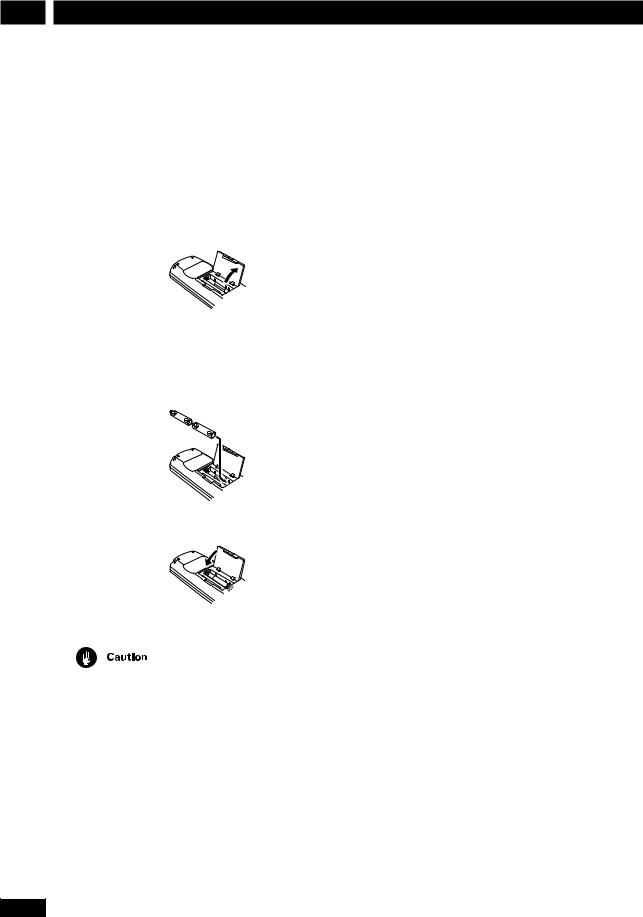
Putting the batteries in the remote control
1Open the battery compartment cover on the back of the remote control.
2Insert two AA/R6P batteries into the battery compartment following the indications (ª, ·) inside the compartment.
3 Close the cover.
•Remove the batteries if the remote is not going to be used for a month or more.
•Remove dead batteries promptly—they can leak and damage the unit.
6
• When disposing of used batteries, please comply with governmental regulations or environmental public institution’s rules that apply in your country or area.
Using the remote control
Keep in mind the following when using the remote control:
•Make sure that there are no obstacles between the remote control and the remote sensor on the unit.
•Use within 7 meters of the remote sensor and at an angle of less than 30º.
•Remote operation may become unreliable if strong sunlight or fluorescent light is shining on the unit’s remote sensor.
•Remote controllers for different devices can interfere with each other. Avoid using remotes for other equipment located nearby this unit.
•Replace the batteries when you notice the operating range of the remote starts to decrease.
Hints on installation
We want you to enjoy using this unit for years to come, so please bear in mind the following points when choosing a suitable location for it:
Do...
Use in a well-ventilated room.
Place on a solid, flat, level surface, such as a table, shelf or stereo rack.
Don’t...
Use in a place exposed to high temperatures or humidity, including near radiators and other heatgenerating appliances.
Place on a window sill or other place where the system will be exposed to direct sunlight.
Use in an excessively dusty or damp environment.
Place directly on top of an amplifier, or other component in your stereo system that becomes hot in use.
En
Before You Start
Use near a television or monitor as you may experience interference—especially if the television uses an indoor antenna.
Use in a kitchen or other room where the system may be exposed to smoke or steam.
Use on a thick rug or carpet, or cover with cloth— this may prevent proper cooling of the unit.
Place on an unstable surface, or one that is not large enough to support all four of the unit’s feet.
Avoiding problems with condensation
Condensation may form inside the system if it is brought into a warm room from outside, or if the temperature of the room rises quickly. Although the condensation won’t damage the system, it may temporarily impair its performance. For this reason you should leave it to adjust to the warmer temperature for about an hour before switching on and using.
Moving the system
If you need to move the system, first switch it off and unplug from the wall outlet. Never lift or move the unit during playback—discs rotate at a high speed and may be damaged.
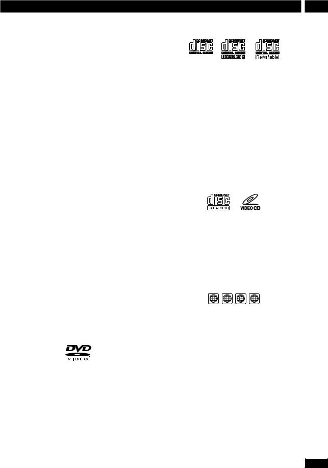
Discs compatible with this system
Any disc that displays one of the following logos should play in this system. Other formats, including DVD-RAM, DVD-ROM, DVD-Audio, CD-ROM, SACD and Photo CD will not play.
DVD Video compatibility:
•Single-sided or double-sided discs
•Single layer or dual layer discs
•Dolby Digital, DTS, MPEG or Linear PCM digital audio
•MPEG-2 digital video
DVD discs are generally divided into one or more titles. Titles may be further subdivided into chapters.
1
Audio CD compatibility:
•12cm or 8cm (5” or 3”) discs
•Linear PCM digital audio
•CD-Audio, CD-R* and CD-RW* formats CDs are divided into tracks.
* This system can play CD-R and CD-RW discs recorded with audio. However, depending on the condition of the player and the disc, you may find that not all discs will play successfully. (For example, if the disc is scratched or dirty, or if the player’s pickup lens is dirty.) Note that this unit cannot record onto recordable discs.
Video CD compatibility:
•12cm or 8cm (5” or 3”) discs
•MPEG-1 digital audio
•MPEG-1 digital video
Video CDs are divided into tracks.
DVD Video regions
2 3 4 ALL
All DVD Video discs carry a region mark on the case somewhere that indicates which region(s) of the world the disc is compatible with. Your DVD system also has a region mark, which you can find on the rear panel. Discs from incompatible regions will not play in this system. Discs marked ALL will play in any player.
7
En
2 Connecting Up
Before making or changing any rear panel connections, make sure that all the components are switched off and unplugged from the power supply.
Center
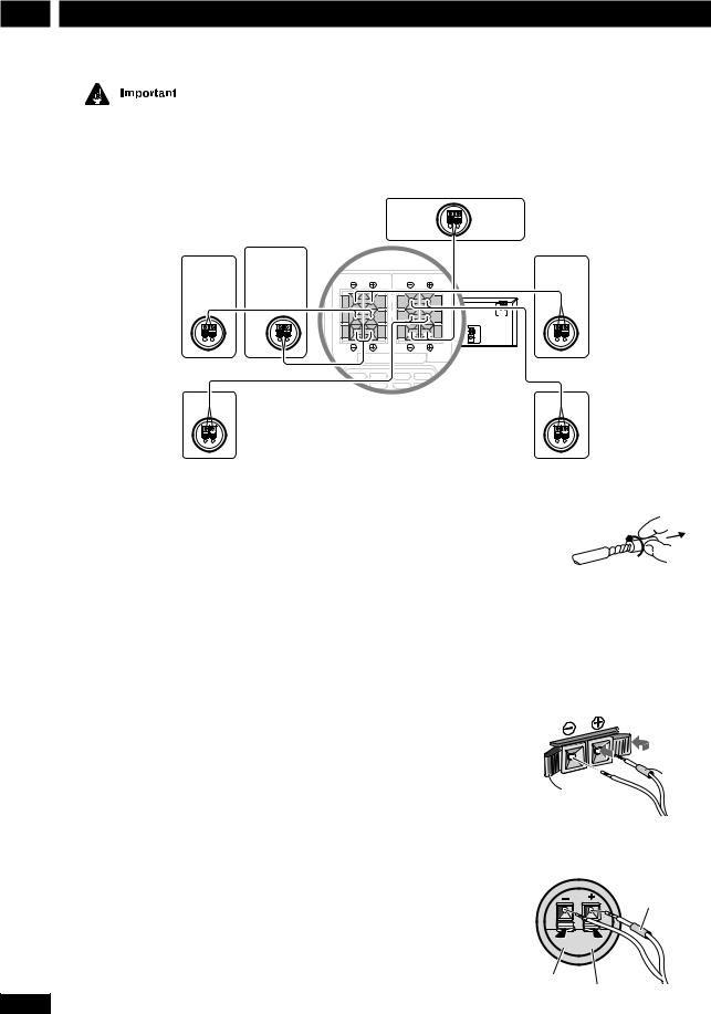
Connecting the speakers
Subwoofer
FRONT |
REAR |
L |
L |
L |
R |
R |
R |
|
SPEAKERS |
|
|
|
H |
|
|
1 |
SUB-
WOOFER SPEAKERS CENTER
Front R
AC INLET
Front L
Rear R
The speaker terminal tabs and supplied speaker cables are color-coded for simpler connection.
1Use the speaker cables with the red sleeves to connect the front speakers to the FRONT L and FRONT R terminals.
2Use the speaker cables with the blue sleeves to connect the rear speakers to the REAR L and REAR R terminals.
3Use the speaker cable with the grey sleeves to connect the subwoofer to the SUBWOOFER terminals.
4Use the speaker cable with the green sleeves to connect the center speaker to the CENTER terminals.
For proper sound, it’s important to connect the positive (colored) and negative (black) terminals for each speaker correctly.
Rear L
1Twist off the protective covers on the ends of the speaker
cable.
2Press the speaker terminal tabs to open and insert the wire with the colored sleeve into the colored terminal and the other wire into the black terminal.
3Release the speaker terminal tabs to secure the
speaker cable.
Colored sleeve
Black tab
4Connect the other end of the cable to the speaker in the same way.
Colored sleeve
Black tab
Colored tab
8
En
Connecting Up |
2 |
Do not connect any of the supplied speakers to any other amplifier. This may result in malfunction or fire.
This DVD receiver has been designed for best performance when connected to the supplied speakers. We do not, therefore, recommend that you connect and use other speakers with this system.
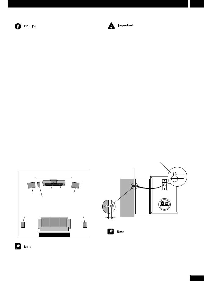
Placing the speakers
Where you put your speakers in the room has a big effect on the quality of the sound. The following guidelines should help you to get the best sound from your system.
•The subwoofer can be placed on the floor. Ideally, the other speakers should be at about ear-level when you’re listening to them. Putting the speakers on the floor (except the subwoofer), or mounting them very high on a wall is not recommended.
•For the best stereo effect, place the front speakers 2– 3m apart.
•The rear speakers should not be further away from your listening position than the front speakers.
•The center speaker should be as close as possible to the TV screen so that movie dialog is localized properly.
2-3 meters |
|
Center |
TV |
Front L |
Front R |
Subwoofer |
|
Rear L |
Rear R |
Your listening position |
|
If you install the center speaker on top of your TV, be sure to secure it with tape or by some other suitable means. An unsecured speaker may fall from the TV due to external shocks such as earthquakes, endangering those nearby or damaging the speaker.
The front and center speakers supplied with this system are magnetically shielded. However, placing them extremely close to a television may result in color distortion on the screen. If this happens, move the speakers a little further away and switch off the television for 15–30 minutes.
The rear speakers and subwoofer are not magnetically shielded, so they should not be placed near a TV or monitor.
Wall mounting the rear speaker system
Before mounting
• Remember that this speaker system is heavy and that its weight may cause the wood screw to work loose or the wall to fail to support it, in which case the speaker system may fall on the floor. This is extremely dangerous. Make absolutely sure that the wall is sturdy enough to support the weight of the speaker system. Do not mount it on plywood boards or soft-surface walls. The mounting screws are not included with this unit. Please find the correct screws for your application.
Wall-mounting bracket
3.5 mm  9.5 mm
Wood screw
Protrude:5-7mm
•If you are unsure of the qualities and strength of the walls, consult a professional for advice.
•PIONEER is not responsible for any accidents or damage that result from improper installation.
9
En
2 Connecting Up
Connecting to your TV
FRONT |
REAR |
L |
L |
COAX |
|
R |
R |
DIGITALR |
|
|
|
|
IN |
TV/ |
|
AC INLET |
|
|
VCR |
IN |
VOLTAGE |
SUB- |
CENTER |
|
SELECTOR |
|
WOOFER |
|
|
|
SPEAKERS |
|
|
|
|
|
240V |
|
DIGITAL |
COAX |
|
R L |
|
|
220- |
|
IN |
TV/ |
|
|
|
|
230V |
|
VIDEO |
VCR |
IN |
|
|
H |
110- |
|
|
|
|
|
AM |
127V |
|
|
VIDEO |
AUX |
|
|
IN |
LOOP |
|
1 |
OUT OUT |
IN |
|
ANTENNA |
|
||
1 |
|
|
|
|
FM |
|
|
|
S-VIDEO |
|
OUT |
AUX |
|
UNBAL |
|
|
OUT |
|
|
75Ω |
|
||
|
|
|
|
|
|
|
|
|
S-VIDEO |
|
|
|
OUT |
|
|
|
OUT |
|
|
|
|
|
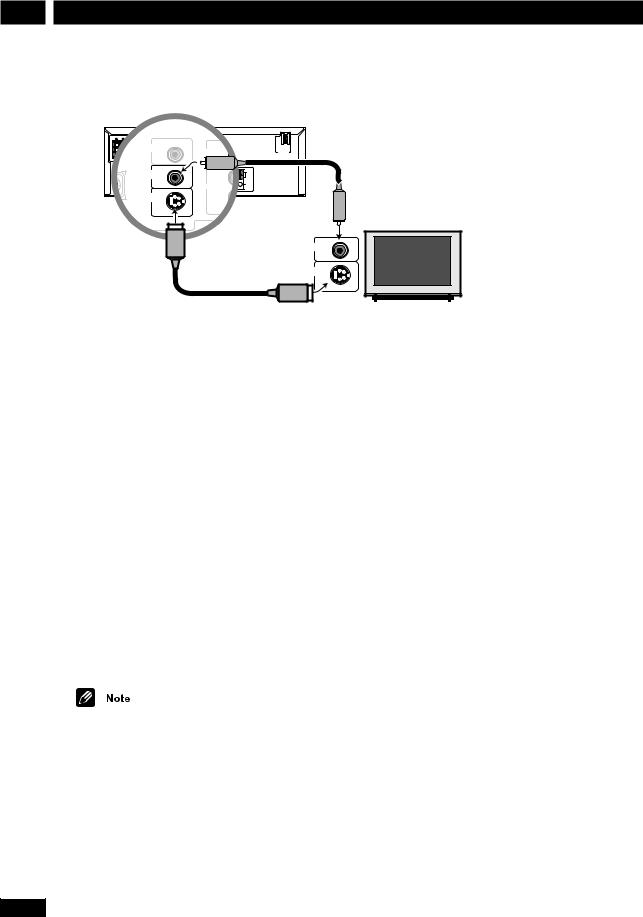
VIDEO
IN
Supplied video cord
S-VIDEO
IN
S-Video cord (not supplied)
1Use the supplied yellow video cord to connect the VIDEO OUT jack to a video input on your TV.
Alternatively, you can use an S-Video cable (not supplied) to connect the S-VIDEO OUT jack to an S- Video input on your TV. S-Video should give you better picture quality than using the standard VIDEO OUT.
• See S-Video Out on page 39 for how to change the S-Video setting between S1 and S2 format.
2Optionally: Use a stereo audio cord to connect the audio outs of your TV (or VCR) to the TV/VCR IN jacks.
This will enable you to hear the TV (or VCR) sound through this system.
• If you want to connect both your TV and VCR, use the TV/VCR IN jacks for one and the AUX IN jacks for the other.
Placing the main unit too close to your TV may cause interference, especially if you’re using an indoor antenna. If you notice interference, move the unit away from the TV.
Setting the TV System
The default setting of this player is AUTO, and unless you notice that the picture is distorted when playing some discs, you should leave it set to AUTO.
If you experience picture distortion with some discs, set the TV system to match your country or region.
1 Make sure that the system is in standby.
2Press SYSTEM SETUP.
The current TV system is shown in the display.
3Use 5 or ∞ to change the TV system.
Switch between auto, ntsc and pal.
4Press ENTER.
The system returns to standby power.
10
En
Connecting Up |
2 |
Connecting the supplied antennas
European model
FM wire
antenna
AM loop antenna
SPEAKERS
ANTENNA
H |
AC INLET |
SELECTORVOLTAGE |
|
AM |
240V |
ANTENNA LOOP |
220- |
|
230V |
||
H |
ANTENNA |
110- |
|
127V |
|
Ω |
FM |
H |
|
|
UNBAL |
|
75Ω |
Except European model
FM wire
antenna
AM loop antenna
SPEAKERS
ANTENNA
H |
AC INLET |
SELECTORVOLTAGE |
|
AM |
240V |
ANTENNA LOOP |
220- |
|
230V |
||
H |
ANTENNA |
110- |
|
127V |
|
Ω FM
H UNBAL
75Ω


 H
H
The supplied antennas provide a simple way to listen to AM and FM radio. If you find that reception quality is poor, an outdoor antenna should give you better sound quality—see Connecting external antennas on page 12 for more on how to do this.
fig. A |
fig. B |
fig. C |
AM loop antenna
1Pull off the protective shields of both AM antenna wires.
2Press the antenna terminal tabs to open and insert one wire into each terminal.
3Release the tabs to secure the AM antenna wires.
4Bend the stand in the direction indicated by the arrow (see fig. A below left).
5Clip the loop onto the stand (fig. B below left).
6Place the AM antenna on a flat surface and point in the direction giving the best reception.
Avoid placing near computers, television sets or other electrical appliances and do not let it come into contact with metal objects.
It’s also possible to fix the AM antenna to a wall. When installing on a wall or other surface, perform steps 4 and 5 after first securing the stand with screws (see fig. C below left). Before fixing, make sure that the reception is satisfactory.
FM wire antenna
•Connect the FM wire antenna to the FM UNBAL 75Ω terminals in the same way as
the AM loop antenna.
For best results, extend the FM antenna fully and fix to a wall or door frame. Don’t drape loosely or leave coiled up.
The signal earth (H) is designed to reduce noise that occurs when an antenna is connected. It is not an electrical safety earth.
11
En
2 Connecting Up
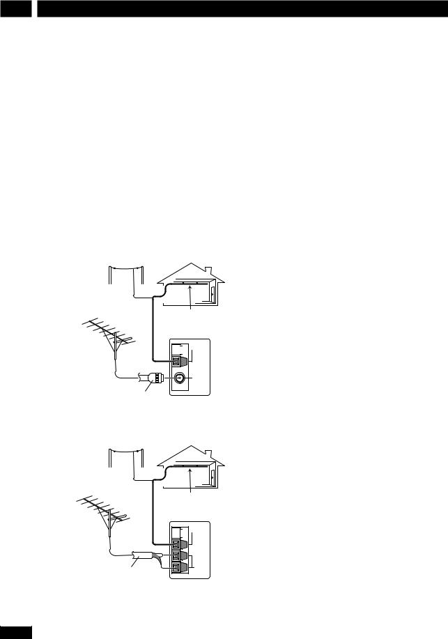
Connecting external antennas
External AM antenna
Use 5–6 meters of vinyl-insulated wire and set up either indoors or outdoors. Leave the supplied AM loop antenna connected.
External FM antenna
Except European model : Use 75Ω coaxial cable to hook up an external FM antenna. Do not leave the supplied FM wire antenna attached.
European model : Use 75Ω coaxial cable with a PAL connector to hook up an external FM antenna.
European model
Outdoor
AM antenna
Indoor
AM antenna


 H
H
AM
LOOP
ANTENNA
FM
UNBAL 75Ω
PAL connector
Except European model
Outdoor
AM antenna
Indoor
AM antenna


 H
H
AM
LOOP
ANTENNA
FM
UNBAL 75Ω
H
75 Ω coaxial cable
12
En
Connecting Up |
2 |
Connecting other components
FRONT |
|
REAR |
|
|
|
|
|
|
|
OAX |
|
|
R |
|
L |
|
|
L |
L |
L |
TV/ |
|
|
|
||
R |
R |
R |
|
|
|
|
|
|
|
|
|
VCR |
|
|
|
|
AC INLET |
|
|
|
|
IN |
|
|
|
VOLTAGE |
|
|
|
|
|
|
|
SELECTOR |
|
SUB- |
SPEAKERS |
CENTER |
|
|
|
|
|
240V |
WOOFER |
|
|
|
|
|
|||
|
|
|
DIGITAL |
COAX |
R |
L |
|
220- |
|
|
|
IN |
|
|
|
|
230V |
|
|
|
|
|
|
|
H |
110- |
|
|
|
OUT |
IN |
|
|
127V |
|
|
|
|
VIDEO |
|
|
|
|
|
|
|
|
1 |
|
|
|
H |
|
|
|
|
AUX |
|
|
|
|
|
|
|
|
VIDEO |
|
|
|
Ω |
|
|
|
|
S-OUT |
|
OUT |
|
|
|
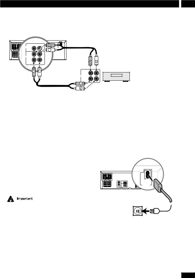
OUT
OUT (PLAY)
Analog
IN (REC)
Tape deck, VCR, MD recorder, etc.
1Use a stereo audio cable to connect the AUX IN jacks to the analog outputs of an external component.
This will allow you to play the component through this system.
2Use a stereo audio cable to connect the AUX OUT jacks to the analog inputs of an external component.
This will allow you to record from this system to an external tape/MD/CD recorder.
3Use a digital coaxial cable to connect the DIGITAL IN COAX jack to the digital output of an external component.
This will allow you to play a digital audio component (MD player, etc.) through this system.
The DIGITAL IN COAX jack should only be connected to a PCM audio output (32, 44.1 or 48kHz). These include CD, MD and DAT players and satellite receivers. Check the instructions that came with your other component for more details.
Connecting the power
Before connecting the power and switching on for the first time make sure that everything is connected properly (See page 3).
1Plug one end of the supplied power cord into the AC INLET.
2Plug the other end into a household power outlet.
SPEAKERS
AC INLET
VOLTAGE
SE ECTOR
13
En
3 Controls & Displays
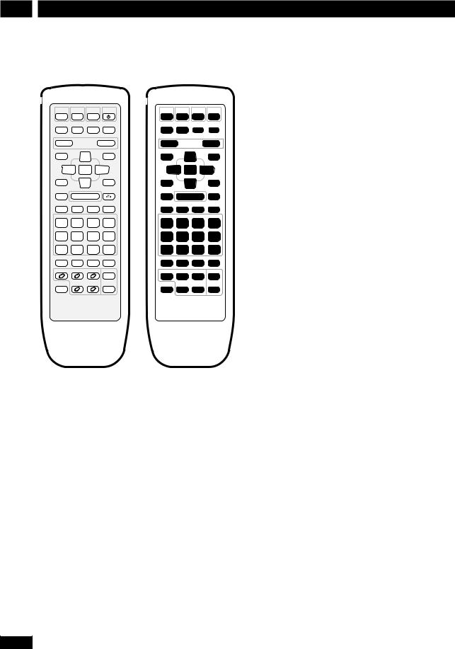
Remote control
DVD |
TUNER |
TV |
STANDBY |
|
|
|
|
/CD |
/BAND |
/AUX |
/ON |
|
|
|
|
|
|
|
|
1 |
2 |
3 |
4 |
MUTE |
TEST TONE SURROUND |
DSP |
|
|
|
|
|
CH LEVEL |
MODE |
|
|
|
|
||
|
|
|
|
5 |
6 |
7 |
8 |
— VOLUME |
+ |
9 |
|
|
10 |
||
DVD SETUP |
|
|
SYSTEM SETUP |
|
|
|
|
|
5 |
|
11 |
|
12 |
13 |
|
|
|
|
|
|
|||
2 ENTER |
3 |
14 |
|
15 |
16 |
||
TOP MENU |
∞ |
|
17 |
|
18 |
19 |
|
MENU |
SOUND |
|
|||||
|
|
|
RETURN |
20 |
|
21 |
22 |
7 |
6 |
|
|
||||
— PREV eSTEP/SLOW E |
NEXT + |
23 |
24 |
25 |
26 |
||
4 |
1 |
¡ |
¢ |
||||
CONDITION |
LAST MEMO |
SEARCH |
DVD DISP |
|
|
|
|
1 |
2 |
3 |
CLEAR |
27 |
28 |
29 |
30 |
ANGLE |
MONO |
SLEEP |
FL DIMMER |
|
|
|
|
4 |
5 |
6 |
>10 |
31 |
32 |
33 |
34 |
PROGRAM |
RANDOM |
REPEAT |
REP A—B |
|
|
|
|
7 |
8 |
9 |
10/0 |
35 |
36 |
37 |
38 |
CD MODE |
AUDIO |
SUBTITLE |
SYSTEM DISP |
|
|
|
|
|
|
|
|
39 |
40 |
41 |
42 |
DISC 1 |
DISC 2 |
DISC 3 |
DISC SKIP |
|
|
|
|
|
|
|
|
43 |
44 |
45 |
46 |
SHIFT |
DISC 4 |
DISC 5 |
OPEN/ |
|
|
|
|
CLOSE |
47 |
48 |
49 |
50 |
|||
|
|
|
0 |
||||
1DVD/CD Pages 19, 34
2 TUNER/BAND Pages 21-22, 34
3 TV/AUX Pages 22, 34
4STANDBY/ON Page 19
5 MUTE Silences/restores all sound.
6 TEST TONE/CH LEVEL Page 17
7 SURROUND MODE Pages 17, 24
8DSP Page 24
9 VOLUME – Lowers the volume.
10VOLUME + Raises the volume.
11DVD SETUP Pages 18, 38
12Cursor up Use for navigating menus and on-screen displays.
13SYSTEM SETUP Pages 16, 22, 34-37, 44
14Cursor left Use for navigating menus and on-screen displays.
14
15ENTER
16Cursor right Use for navigating menus and on-screen displays.
17MENU Page 20
TOP MENU Page 20
18Cursor down Use for navigating menus and on-screen displays.
19SOUND Page 24, 25
207 Page 19
213/8Page 19
22RETURN  Page 20
234 / –PREV Pages 19-20
241/ STEP/SLOW ePages 19-20
25¡/ STEP/SLOW EPages 19-20
26¢ / NEXT+ Pages 19-20
271 / CONDITION (SHIFT & 1) Page 30
282 / LAST MEMO (SHIFT & 2) Page 29
293 / SEARCH (SHIFT & 3) Page 26
30CLEAR Clears/cancels various functions
DVD DISP (SHIFT & CLEAR) Page 30
314 / ANGLE (SHIFT & 4) Page 26
325 / MONO (SHIFT & 5) Page 22
336 / SLEEP (SHIFT & 6) Page 35
34>10 Selects numbers over 10 Page 20
FL DIMMER (SHIFT & >10) Page 44
357 / PROGRAM (SHIFT & 7) Page 28
368 / RANDOM (SHIFT & 8) Page 28
379 / REPEAT (SHIFT & 9) Page 28
38REP A–B (SHIFT & 10/0) Page 29
10/0 Number button (10 and 0)
39CD MODE Page 29
40AUDIO Page 26
41SUBTITLE Page 26
42SYSTEM DISP Page 16
43DISC 1 Page 20
44DISC 2 Page 20
45DISC 3 Page 20
46DISC SKIP Pages 19, 21
47SHIFT Hold down to access secondary button functions
48DISC 4 Page 20
49DISC 5 Page 20
50OPEN/CLOSE 0Pages 19, 21
En
Controls & Displays |
3 |
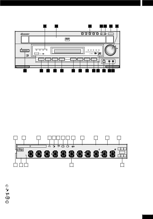
Front panel |
|
|
|
|
|
|
|
|
|
This illustration is not European model. |
|||||
|
|
|
|
|
|
|
|
|
|
|
|
|
|
|
|
|
1 |
|
2 |
|
|
|
|
|
3 |
|
|
4 |
5 |
6 |
7 |
|
|
|
|
|
|
|
|
|
|
|
|
DISC SKIP EXCHANGE |
0 OPEN/CLOSE |
||
|
|
|
|
|
|
1 |
2 |
3 |
|
4 |
5 |
|
|
|
|
|
|
|
|
|
VIDEO |
|
|
|
|
|
|
|
|
|
|
|
|
|
|
|
|
|
|
|
|
|
|
|
|
|
VOLUME |
DVD RECEIVER XV-HTD1 |
|
|
|
|
|
|
|
|
|
|
|
|
|
|
|
STANDBY/ON |
|
|
|
|
|
|
|
|
|
|
|
|
|
|
|
STANDBY |
CD ADVANCED |
DSP |
|
|
|
|
|
DISC 1 |
2 |
3 |
4 |
5 |
|
|
|
|
MODE THEATER |
|
|
|
|
|
|
|
|
|
|
|
|
|
|
|
Karaoke |
|
|
|
|
|
|
|
|
|
|
|
|
|
|
1 |
|
|
|
|
|
|
|
|
|
|
|
|
|
|
|
|
DVD/CD |
TUNER/BAND |
TV/AUX |
CD MODE |
7 |
3/8 |
|
4.1 |
|
¡.¢ |
|
|
|
|
|
|
|
|
|
|
|
|
|
|
|
|
|
|
MIC |
|
|
|
|
|
|
|
|
|
|
|
|
|
|
|
LEVEL |
|
|
|
|
|
|
|
|
|
|
|
|
|
|
|
|
MIC |
PHONES |
20 |
19 |
18 |
17 |
16 |
15 |
14 |
|
13 |
|
12 |
|
11 |
10 |
9 |
8 |
1 |
STANDBY indicator |
|
|
|
|
|
|
|
|
|
|
|
9 |
|
Mic input (Except European model) |
|||||||||||||
|
CD MODE indicator |
|
|
|
|
|
|
|
|
|
|
|
10 |
Mic volume (Except European model) |
||||||||||||||
|
ADVANCED THEATER indicator |
|
|
|
|
|
|
|
|
|
11 |
DISC indicators |
|
|
|
|
||||||||||||
|
DSP indicator |
|
|
|
|
|
|
|
|
|
|
|
12 |
¡• ¢ Pages 19-20 |
|
|
|
|
||||||||||
2 |
Disc tray |
|
|
|
|
|
|
|
|
|
|
|
|
|
13 |
4 • 1 Pages 19-20 |
|
|
||||||||||
3 |
Disc buttons Page 20 |
|
|
|
|
|
|
|
|
|
|
|
14 |
6 Page 19 |
|
|
|
|
|
|
||||||||
4 |
DISC SKIP Pages 19, 21 |
|
|
|
|
|
|
|
|
|
|
|
15 |
7 Page 19 |
|
|
|
|
|
|
||||||||
5 |
EXCHANGE Page 21 |
|
|
|
|
|
|
|
|
|
|
|
16 |
CD MODE Page 29 |
|
|
|
|
||||||||||
6 |
0OPEN/CLOSE Pages 19, 21 |
|
|
|
|
|
|
|
|
|
17 |
TV/AUX (/DIGITAL IN) Pages 22, 34 |
||||||||||||||||
7 |
VOLUME Turn to adjust the volume. |
|
|
|
|
|
|
|
|
|
18 |
TUNER/BAND Pages 21-22 |
|
|
||||||||||||||
8 |
PHONES Plug in a pair of headphones here. |
|
|
|
|
|
|
19 |
DVD/CD Pages 19, 34 |
|
|
|
|
|||||||||||||||
|
|
|
|
|
|
|
|
|
|
|
|
|
|
|
|
|
20 |
STANDBY/ON Page 19 |
|
|
||||||||
|
Display |
|
|
|
|
|
|
|
|
|
|
|
|
|
|
|
|
|
|
|
|
|
|
|
|
|
||
|
|
|
|
|
|
|
|
|
|
|
|
|
|
|
|
|
|
|
|
|
|
|
|
|
|
|
|
|
|
|
1 |
|
2 |
|
3 |
|
4 |
|
5 |
|
6 |
|
7 |
|
8 |
|
9 |
|
|
10 |
|
11 |
|
12 |
|
13 |
|
2DIGITAL |
2PRO LOGIC |
MIDNIGHT |
CONDITION |
ANGLE |
LAST MEMO |
||
|
|
|
|
|
L |
C |
R |
ALL DISCS |
|
|
|
|
|
LFE |
|
|
|
|
|
|
|
|
|
RANDOM |
|
|
|
|
Ls |
S |
Rs |
REPEAT |
|
|
|
|
|||
|
|
|
|
|
|
|
|
|
|
18 |
|
17 |
|
16 |
|
15 |
|
|
14 |
|
1 |
DTS pages 23, 46 |
|
|
11 |
CONDITION page 30 |
|||||||
2 |
2DIGITAL pages 23, 46 |
12 |
ANGLE page 26 |
|||||||||
3 |
2PRO LOGIC page 23 |
13 |
LAST MEMO page 29 |
|||||||||
4 |
Timer indicator page 34 |
14 |
Channel indicators Show which channels are available |
|||||||||
5 |
Sleep indicator page 35 |
|
|
on the current disc. |
||||||||
6 |
Tuned indicator page 21-22 |
15 |
Character display When playing discs : Left to right |
|||||||||
7 |
FM stereo indicator page 22 |
|
|
displays disc number, title, chapter/track, minutes, seconds. |
||||||||
8 |
FM mono indicator page 22 |
16 |
RANDOM page 28 |
|||||||||
9 |
RDS (European model only) Lights when in one of |
17 |
REPEAT page 28 |
|||||||||
|
the RDS display or search modes |
18 |
DISC | ALL DISCS Indicates the random or repeat |
|||||||||
10 |
MIDNIGHT page 25 |
|
|
mode ; page 28–29 |
||||||||
15
En
4 Setting Up
Switching on and setting the clock
This system has a built-in clock, which needs to be set to be able to use the timer features.
STANDBY /ON
SYSTEM SETUP
5
2ENTER 3
∞
SYSTEM DISP
1 Press to switch on.
2 Press SYSTEM SETUP.
3Press the 2 or 3 button until you see
TIMER in the display.
4 Press ENTER.
5Press 2 or 3 until you see CLOCK ADJ in the display.
6Press ENTER.
The display shows a clock, with the hour blinking.
7Use the 5 and ∞ buttons to set the hour, then press ENTER.
8Use the 5 and ∞ buttons to set the minute, then press ENTER.
The display blinks to indicate that the time has been set.
• Press SYSTEM DISP anytime to see the clock when the system is on or in standby.
Setting up for surround sound
You can use this system right out of the box for surround sound with just the default settings. However, for really great surround sound, we recommend that you spend a few minutes making some settings that match this system to your listening room. Unless you change the layout of your speakers or main listening position, you only need to make most of these settings once.
TEST TONE |
SURROUND |
/CH LEVEL |
MODE |
–VOLUME +
SYSTEM SETUP
5
2 ENTER 3
∞
SHIFT
Setting the speaker distances
1 Press SYSTEM SETUP.
2Press the 2 or 3 button until you see
FRT. SP in the display.
3Use the 5 and ∞ buttons to set the distance from your main listening position to the front speakers.
Ideally, your listening position should be equidistant from the two front speakers.
The default setting is 3m. You can adjust the range from 0.3m to 9.0m in steps of 0.3m.
16
En
 Loading...