


DVR-440HX-S
Table of contents
 Loading...
ORDER NO.
PIONEER CORPORATION 4-1, Meguro 1-chome, Meguro-ku, Tokyo 153-8654, Japan
PIONEER ELECTRONICS (USA) INC. P.O. Box 1760, Long Beach, CA 90801-1760, U.S.A.
PIONEER EUROPE NV Haven 1087, Keetberglaan 1, 9120 Melsele, Belgium
PIONEER ELECTRONICS ASIACENTRE PTE. LTD. 253 Alexandra Road, #04-01, Singapore 159936
PIONEER CORPORATION 2006
HDD/DVDOPEN/CLOSE
REC STANDBY/ON
ONE TOUCH
COPY
CH
STANDBY/ON
REC
+
–
A.TV/D.TVHELP
INPUT
SELECT
PAUSE
LIVE TV
PLTVDivXD.TVA.TV
S-VIDEO VIDEO L(MONO) R
AUDIO
INPUT 2
DVR-540HX-S
RRV3396
DVD RECORDER
DVR-540HX-S
DVR-440HX-S
THIS MANUAL IS APPLICABLE TO THE FOLLOWING MODEL(S) AND TYPE(S).
Model Type Power Requirement Region No.
Serial No.
Please confirm 3rd & 4th
alphabetical letters.
DVR-540HX-S WYXK5 AC 220 V to 240 V 2 &&UK######$$
DVR-540HX-S WVXK/5 AC 220 V to 240 V 2 &&UK######$$
DVR-440HX-S WVXK5 AC 220 V to 240 V 2 &&UK######$$
÷ When servicing this model, some service procedures may reset the customer settings
to the factory default settings. Make sure to explain this to the customer.
An HDD (Hard Disc Drive) is mounted in this product.
The HDD is a precision instrument very vulnerable to shock and electrostatic charges. Please read
"7.3 Cautions on Handling the HDD" in this manual and exercise sufficient caution when handling the
HDD itself, as well as the product with the HDD built in.
When an HDD becomes defective and inoperable, restoration of the user's data recorded on the HDD,
or copying of the user's recorded data to other media (such as a new HDD) is totally impossible.
Before servicing, OBTAIN THE USER'S PRIOR CONSENT to that effect.
The user must be made aware that all recorded data are deleted if the HDD is intialized.
For details, refer to "Important Check Points for Good Servicing" .
T-ZZV MAY 2006 printed in Japan
DVR-540HX-S
2
1234
1234
C
D
F
A
B
E
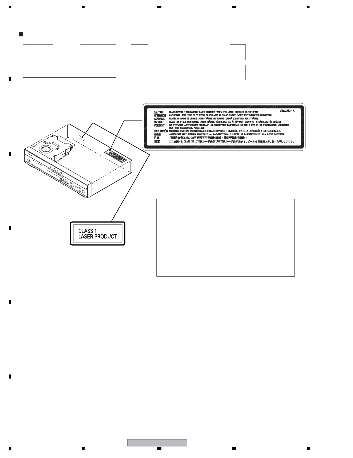
SAFETY INFORMATION
LABEL CHECK
IMPORTANT
THIS PIONEER APPARATUS CONTAINS
LASER OF CLASS 1.
SERVICING OPERATION OF THE APPARATUS
SHOULD BE DONE BY A SPECIALLY
INSTRUCTED PERSON.
CLAMP signals for detecting the loading state are detected
by the drive CPUs, and the design prevents laser diode
oscillation when the CLAMP signal turns OFF.
In normal operation, if no disc is clamped, the laser diode
oscillation is disabled.
However, the interlock does not always operate in the test
mode.
2. When the cover is opened, close viewing of the objective
lens with the naked eye will cause exposure to a Class 3A
laser beam.
Additional Laser Caution
1. The ON/OFF(ON:low level,OFF:high level) status of the
LASER DIODE CHARACTERISTICS
MAXIMUM OUTPUT POWER: 100 mW
WAVELENGTH: 654 - 662 nm
LASER DIODE CHARACTERISTICS
MAXIMUM OUTPUT POWER: 5 mW
WAVELENGTH: 770 - 810 nm
VRW2262
HDD/DVD
OPEN/CLOSE
R
E
C
S
T
A
N
D
B
Y
/
O
N
O
N
E
T
O
U
C
H
C
O
P
Y
CH
STANDBY/ON
REC
+
–
A
.
T
V
/
D
.
T
V
H
E
L
P
I
N
P
U
T
S
E
L
E
C
T
P
A
U
S
E
L
I
V
E
T
V
P
L
T
V
D
i
v
X
D
.
T
V
A
.
T
V
S
-
V
I
D
E
O
V
I
D
E
O
L
(
M
O
N
O
)
R
A
U
D
I
O
I
N
P
U
T
2
DVR-540HX-S
3
5678
56
7
8
C
D
F
A
B
E
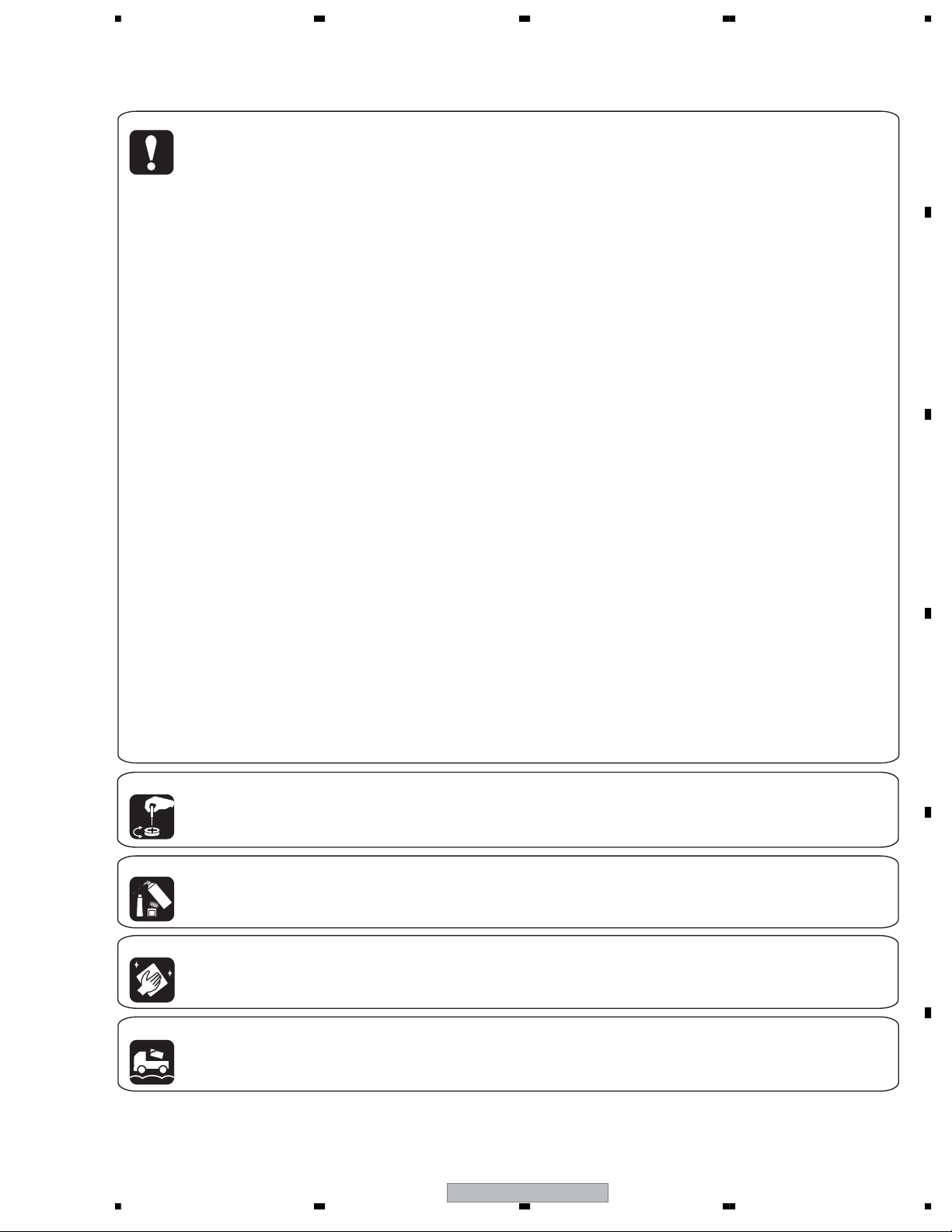
[Important Check Points for Good Servicing]
In this manual, procedures that must be performed during repairs are marked with the below symbol.
Please be sure to confirm and follow these procedures.
1. Product safety
Please conform to product regulations (such as safety and radiation regulations), and maintain a safe servicing environment by
following the safety instructions described in this manual.
1 Use specified parts for repair.
Use genuine parts. Be sure to use important parts for safety.
2 Do not perform modifications without proper instructions.
Please follow the specified safety methods when modification(addition/change of parts) is required due to interferences such as
radio/TV interference and foreign noise.
3 Make sure the soldering of repaired locations is properly performed.
When you solder while repairing, please be sure that there are no cold solder and other debris.
Soldering should be finished with the proper quantity. (Refer to the example)
4 Make sure the screws are tightly fastened.
Please be sure that all screws are fastened, and that there are no loose screws.
5 Make sure each connectors are correctly inserted.
Please be sure that all connectors are inserted, and that there are no imperfect insertion.
6 Make sure the wiring cables are set to their original state.
Please replace the wiring and cables to the original state after repairs.
In addition, be sure that there are no pinched wires, etc.
7 Make sure screws and soldering scraps do not remain inside the product.
Please check that neither solder debris nor screws remain inside the product.
8 There should be no semi-broken wires, scratches, melting, etc. on the coating of the power cord.
Damaged power cords may lead to fire accidents, so please be sure that there are no damages.
If you find a damaged power cord, please exchange it with a suitable one.
9 There should be no spark traces or similar marks on the power plug.
When spark traces or similar marks are found on the power supply plug, please check the connection and advise on secure
connections and suitable usage. Please exchange the power cord if necessary.
0 Safe environment should be secured during servicing.
When you perform repairs, please pay attention to static electricity, furniture, household articles, etc. in order to prevent injuries.
Please pay attention to your surroundings and repair safely.
2. Adjustments
To keep the original performance of the products, optimum adjustments and confirmation of characteristics within specification.
Adjustments should be performed in accordance with the procedures/instructions described in this manual.
4. Cleaning
For parts that require cleaning, such as optical pickups, tape deck heads, lenses and mirrors used in projection monitors, proper
cleaning should be performed to restore their performances.
3. Lubricants, Glues, and Replacement parts
Use grease and adhesives that are equal to the specified substance.
Make sure the proper amount is applied.
5. Shipping mode and Shipping screws
To protect products from damages or failures during transit, the shipping mode should be set or the shipping screws should be
installed before shipment. Please be sure to follow this method especially if it is specified in this manual.

DVR-540HX-S
4
1234
1234
C
D
F
A
B
E
CONTENTS
SAFETY INFORMATION..................................................................................................................................... 2
1. SPECIFICATIONS ............................................................................................................................................ 5
2. EXPLODED VIEWS AND PARTS LIST ............................................................................................................ 8
2.1 PACKING ................................................................................................................................................... 8
2.2 EXTERIOR SECTION.............................................................................................................................. 10
2.3 SERVICE LOADER MAIN........................................................................................................................ 12
2.4 FRONT PANEL SECTION ....................................................................................................................... 14
3. BLOCK DIAGRAM AND SCHEMATIC DIAGRAM..........................................................................................16
3.1 BLOCK DIAGRAM ................................................................................................................................... 16
3.1.1 OVERALL BLOCK DIAGRAM............................................................................................................ 16
3.2 OVERALL WIRING DIAGRAM................................................................................................................. 18
3.3 JACB ASSY (1/3)..................................................................................................................................... 20
3.4 JACB ASSY (2/3)..................................................................................................................................... 26
3.5 JACB ASSY (3/3)..................................................................................................................................... 32
3.6 TUNB ASSY ............................................................................................................................................. 34
3.7 DTBR ASSY (1/2) .................................................................................................................................... 36
3.8 DTBR ASSY (2/2) .................................................................................................................................... 38
3.9 FRJB, FLKY and PWSB ASSYS.............................................................................................................. 40
3.10 MAIN ASSY(1/3) .................................................................................................................................... 42
3.11 MAIN ASSY(2/3) .................................................................................................................................... 44
3.12 MAIN ASSY(3/3) .................................................................................................................................... 46
3.13 ATAB ASSY ............................................................................................................................................ 48
3.14 POWER SUPPLY UNIT.......................................................................................................................... 50
3.15 WAVE FORMS ....................................................................................................................................... 52
4. PCB CONNECTION DIAGRAM ..................................................................................................................... 59
4.1 JACB ASSY ............................................................................................................................................. 60
4.2 TUNB ASSY ............................................................................................................................................. 64
4.3 DTBR ASSY............................................................................................................................................. 66
4.4 FLKY and PWSB ASSYS ........................................................................................................................ 70
4.5 MAIN ASSY ............................................................................................................................................. 74
4.6 ATAB ASSY .............................................................................................................................................. 78
4.7 POWER SUPPLY UNIT............................................................................................................................ 80
5. PCB PARTS LIST ........................................................................................................................................... 82
6. ADJUSTMENT ............................................................................................................................................... 87
7. GENERAL INFORMATION ............................................................................................................................. 89
7.1 DIAGNOSIS ............................................................................................................................................. 89
7.1.1 MODEL SETTING.............................................................................................................................. 91
7.1.2 CPRM ID NUMBER AND DATA SETTING......................................................................................... 92
7.1.3 FIRMWARE DOWNLOADING METHOD........................................................................................... 96
7.1.4 VIDEO ADJUSTMENT FOR SPECIFIC AREA.................................................................................. 99
7.1.5 SERVICE MODE.............................................................................................................................. 103
7.1.6 EPG SERVICE MODE..................................................................................................................... 115
7.1.7 AGING MODE.................................................................................................................................. 117
7.1.8 HDD CHECK MODE........................................................................................................................ 119
7.1.9 DIAGNOSIS OF THE MAIN ASSY................................................................................................... 125
7.1.10 DIAGNOSIS OF THE DTBR ASSY................................................................................................ 126
7.1.11 NOTE ON REPLACEMENT OF THE SDRAM............................................................................... 127
7.1.12 SETUP SEQUENCE...................................................................................................................... 128
7.1.13 DISASSEMBLY .............................................................................................................................. 129
7.2 IC ........................................................................................................................................................... 135
7.3 CAUTIONS ON HANDLING THE HDD.................................................................................................. 150
7.4 DISC/CONTENT FORMAT .................................................................................................................... 152
8. PANEL FACILITIES ...................................................................................................................................... 155

DVR-540HX-S
5
5678
56
7
8
C
D
F
A
B
E
1. SPECIFICATIONS
. . . . . . . .
. . . . . . . . . . . . . . . . . . . . . . . . . . . . . .
. . . . . . . . . . . . . . . . . . . . . . . . . . . . . . . . . . . . . . . . .
. . . . . . . . . . . . . . . . . . . . . . . . .
. . . . . . .
. . . . . . . . . . . . . . . . . . . . . . . . . . .
. . . . . . . . . . . . . . . . . . . . . . . . . . . . .
. . . . . . . . . . . . . . . . . . . . . . . . . . . . .
. . . . . . . . . . . . . . . . . . . . . . . . . . . . . . . . .
. . . . . . . . . . . . . . . . . . . . . . . . . . . . . . . . . .
. . . . . . . . . . . . . . . . . . . . . . . . . . . . .
. . . . . . . . . . . . . . . . . . . . . . . . .
. . . . . . . . . . . . . . . . . . . . . .
. . . . . . . . . . . . . . . . . . . . . . .
. . . . . . . . . . . . . . . . .
. . . . . . . . . . . . . . . . .
. . . . . . . . . . . . . . . . . . . . . . . . .
. . . . . . . . . . . . . . . . . . . . . . . . . . .
. . . . . . . . . . . . . . . . . . . . . . .
. . . . . . . . . . . . . . . .
. . . . . . . . . . . . . . . . . . . .
. . . . . . . . . . . . . . . .
. . . . . . . . . . . . . . . . . . . . . . . .
. . . . . . . . . . . . . . . . . . . . . . . . . . . . . . . . .
. . . . . . . . . . . . . . . . . . . . . . . . . . .
. . . . . . . . . . . . . . . . . . . . . . .
. . . . . . . . . . . . . . . .
. . . . . . . . . . . . . . . . . . . .
. . . . . . . . . . . . . . . .
. . . . . . . . . . . . . . . . . . . . . . . .
. . . . . . . . .
. . . . . . . . . . . . . . . . . .
. . . . . . . . . . . . .
. . . . . . .
. . . . . . . . . . . . . . . . . . . . . . . . . . . . .
. . . . . . . . . . . . . . . . . . . . . . . . .
. . . . . . . . . . . . . . . .
. . . . . . . . . . . . . . . . . . . . . . . .
. . . . . . . . . . . . . . . . . . .
. . . . . . . . . . . . . . . . . . .
. . . . . . . . . . . . . .
. . . . . . . . . . . .
. . . . . . . . . . . . . . . . . . . .
. . . . . . . . . . . . .
. . . . . . . . . . . . . . . .
. . . . . . . . . . . . . . . . . . . . . . . . . . .
. . . . . . .
General
Power requirements 220 V to 240 V, 50 Hz / 60 Hz
Power consumption 48 W
Power consumption in standby mode 0.63 W
(Front panel display : off)
Weight 4.5 kg
Dimensions 420 mm (W) x 79 mm (H) x 318 mm (D)
Operating temperature +5 °C to +35 °C
Operating humidity 5 % to 85 %
(no condensation)
TV system PAL/SECAM/NTSC (external input only)
Readable discs
DVD-Video, DVD-RW, DVD-R, DVD+R, DVD+RW,
DVD-RAM, Video CD, Super VCD, CD, CD-R/-RW
(WMA, MP3, JPEG, CD-DA)
Recording discs and formats
DVD-R/-RW : VR mode and Video mode
DVD+R/+RW : +VR mode
DVD-RAM : VR mode
DVD-R DL : VR mode and Video mode
DVD+R DL : +VR mode
Video recording format
Sampling frequency 13.5 MHz
Compression format MPEG
Audio recording format
Sampling frequency 48 kHz
Compression format Dolby Digital or Linear PCM
(uncompressed)
Recording time
HDD (160 GB) (DVR-540HX-S)
Fine (XP) Approx. 34 h
Standard Play (SP) Approx. 68 h
Long Play (LP) Approx. 136 h
Extended Play (EP) Approx. 204 h
Super Long Play (SLP) Approx. 272 h
Super Extended Play (SEP) Approx. 340 h
Manual Mode (MN) Approx. 34 h to 455 h
HDD (80 GB) (DVR-440HX-S)
Fine (XP) Approx. 17 h
Standard Play (SP) Approx. 34 h
Long Play (LP) Approx. 68 h
Extended Play (EP) Approx. 102 h
Super Long Play (SLP) Approx. 136 h
Super Extended Play (SEP) Approx. 170 h
Manual Mode (MN) Approx. 17 h to 227 h
DVD-R/-RW, DVD+R/+RW, DVD-RAM
Fine (XP) Approx. 1 h
Standard Play (SP) Approx. 2 h
Long Play (LP) Approx. 4 h
Extended Play (EP) Approx. 6 h
Super Long Play (SLP) Approx. 8 h
Super Extended Play (SEP) Approx. 10 h
(DVD-R/-RW, DVD-RAM only)
Manual Mode (MN)
DVD-R/-RW/-RAM Approx. 1 h to 13 h
DVD+R/+RW Approx. 1 h to 8 h
DVD-R DL/DVD+R DL
Fine (XP) Approx. 1 h 51 m
Standard Play (SP) Approx. 3 h 35 m
Long Play (LP) Approx. 7 h 11 m
Extended Play (EP) Approx. 10 h 46 m
Super Long Play (SLP) Approx. 14 h 21 m
Super Extended Play (SEP) Approx. 17 h 57 m
(DVD-R DL only)
Manual Mode (MN)
DVD-R DL Approx. 1 h 51 m to 24 h
DVD+R DL Approx. 1 h 51 m to 14 h 21 m
Timer
Programs 1 month/32 programs
Clock Quartz lock (24-hour digital display)
Tuner (analog)
Receivable channels
Tuner (digital)
Receiving system DVB-T (2 K / 8 K COFDM)
Tuner VHF/UHF VHF band III (170 MHz to 230 MHz)
UHF band IV, V (470 MHz to 862 MHz)
Auto Channel Preset 999 ch, Auto Preset
Auto Label, Auto Sort
Audio Stereo MPEG layer I/II
This product’s digital tuner has been confirmed for use in
the following countries: Belgium, France, Germany, Italy,
Spain, UK.
VHF
(low)
VHF
(high)
Hyper
UHF
VHF
(low)
VHF
(high)
Hyper
UHF
Channel
E2 to E4
X to Z
E5 to E12
S1 to S20
M1 to M10
U1 to U10
S21 to S41
E21 to E69
Frequency
47 MHz to 89 MHz
104 MHz to 300 MHz
302 MHz to 470 MHz
470 MHz to 862 MHz
Channel
A to C
X to Z
D to J
11, 13
S1 to S20
S21 to S41
E21 to E69
Frequency
44 MHz to 89 MHz
104 MHz to 300 MHz
302 MHz to 470 MHz
470 MHz to 862 MHz
SECAM B/G
PAL B/G
PAL I
Channel
FB,FC1,FC
F1 to F6
B to Q
S21 to S41
21 to 69
Frequency
49 MHz to 65 MHz
104 MHz to 300 MHz
300 MHz to 470 MHz
470 MHz to 862 MHz
Channel
R1 to R5
R6 to R12
S1 to S20
S21 to S41
E21 to E69
Frequency
49 MHz to 94 MHz
104 MHz to 300 MHz
302 MHz to 470 MHz
470 MHz to 862 MHz
SECAM L
SECAM D/K
PAL D/K
STEREO
B/G - A2
I - NICAM
L - NICAM
B/G - NICAM
D/K - NICAM
Specifications

DVR-540HX-S
6
1234
1234
C
D
F
A
B
E
. . . . . . . . . . . . . . . . . .
. . . . . . . . . . . . . . . . . . . . . . . . . . . . . .
. . . . . . . . . . . . . . . . . . . . . . . . . . . . . . .
. . . . . . . . . . . . . . . .
. . . . . . . . . . . . . . . . . . . . . . . . . . . . .
. . . . . . . . . . . . . . . . . . . . . . . . . . . .
. . . . . . . . . . . . . . . . . . . . . . . . . . . . .
. . . . . . . . . . . . . . . . . . . . . . . .
. . . . . . . . . . . . . . . . . . . . . . . . . . . . . . . . . . . . .
. . . . . . . . . . . . . . . . . . . . . . . . . . . . . . . . . . . . . . .
. . . . . . . . . . . . . . . . . . . . . . . . . . . .
. . . . . . . . . . . . . . . . . . . . . . . . . . . . . . . . . .
. . . . . . . . . . . . . . . . . . . . . . . . . . . . . . . . . . . . .
. . . . . . . . . . . . . . . . . . . . . . . . . . . . .
. . . . . . . . . . . . . . . . . . . . . . . . . .
. . . . . . . . . .
. . . . . . .
. . . . . . . . . . . . . . . . . . . . . . . . . . . .
. . . . . . . . . . . . . . .
. . . . . . . . . . . . . . . . . . . . . . . . . . .
. . . . . . . . . . . . . . . . . . . . . . . . . .
. . . . . . . . . . . . . . . . . . . . . . . . . . . . .
. . . . . . . . . . . . . . . . . . . . . . . . . . . . . . . .
. . . . . . . . . . . . . .
. . . . . . . . . . . . . . .
. . . . . .
. . . . . . . . . . . . . . . .
. . . . . . . . . . . . . . . .
. . . .
. . . . . . . .
. . . . . .
. . . . .
. . . . . . . . . . . . . . . . . . . . . . . . . .
. . . . . . . . . . . . . . . . . . . . . . . . . . . . . . . . . . . . .
. . . . . . . . . . . . . . . . . . . . . . . . . . . . . . . . . . . . .
. . . . . . . . . . . . . . . . . . . . . . . . . . . . . . . . . . . . . . . . . . . . . . . .
. . . . . . . . . . . . . . . . . . . . . . . . . . . . . . . . . . . . . . . . . . . . . . .
. . . . . . . . . . . . . . . . . . . . . . . . . . . . . . . . . . . . . . . . . . . . . .
. . . . . . . . . . . . . . . . . . . . . . . . . . . . . . . . . . . . . . . . . . . . . . .
. . . . . . . . . . . . . . . . . . . . . . . . . . . . . . . . . . . . . .
. . . . . . . . . . . . . . . . . . . . . . . . . . . . . . . . . . . . . .
. . . . . . . . . . . . . . . . . . . . . . . . . . . . . . . . . . . . . . . . .
. . . . . . . . . . . . . . . . . . . . . . . . . . . . . . . . . . . . . . .
. . . . . . . . . . . . . . . . . . .
. . . . . . . . . . . . . . . . . . . . . . . . . . . .
. . . . . . . . . . . . . . . . . .
. . . . . . . . . . . . . . . . . . . . . . . . . . . . . . . . . .
. . . . . . . . . . . . . . . . . . . . . . . . . . . . . . . . . . . . . . . . . . .
. . . . . . . . . . . . . . . . . . . . . . . . .
. . . . . . . . . . . . . . . . . . . . . . . . . . .
. . . . . . . . . . . . . . . . . . . . . . . . . . . . . . . . . . . . . . . . .
. . . . . . . . . . . . . . . . . . . . . . . . . . . . . . . .
. . . . . . . . . . . . . . .
Input/Output
Antenna
75Ω IEC 169-2 connector for VHF/UHF in/out (analog)
75Ω IEC 169-2 connector for VHF/UHF in/out (digital)
Video input AV2 (Input1), Input 2 (front)
Input level 1 Vp-p (75Ω)
Jacks AV connector (Input 1), RCA jack (Input 2)
Video output AV1, Output
Output level 1 Vp-p (75Ω)
Jacks AV connector (AV1)
RCA jack (Output)
S-Video input AV2 (Input1), Input 2 (front)
Y (luminance) - Input level 1 Vp-p (75Ω)
C (colour) - Input leve 300 mVp-p (75Ω)
Jacks AV connector (Input 1), 4 pin mini DIN (Input 2)
S-Video output AV1, Output
Y (luminance) - Output level 1 Vp-p (75Ω)
C (colour) - Output level 300 mVp-p (75Ω)
Jacks AV connector (AV1), 4 pin mini DIN (Output)
Component video output
Output level Y : 1.0 Vp-p (75Ω)
PB, PR : 0.7 Vp-p (75Ω)
Jacks RCA jacks
RGB input AV2 (Input1)
Input level 0.7 Vp-p (75Ω)
Jacks AV connector (Input 1)
RGB output AV1
Output level 0.7 Vp-p (75Ω)
Jacks AV connector (AV1)
Audio input AV2 (input1), Input 2 (front) L/R
Input level
During audio input 2 V rms
(Input impedance: more than 22 kΩ)
Jacks AV connector (Input 1), RCA jacks (Input 2)
Audio output AV1, Output
During audio output 2 V rms
(Output impedance: less than 1.5 kΩ)
Jacks AV connector (AV1), RCA jacks (Output)
Control input Mini jack
Digital audio ouptut Coaxial
G-LINK™ Mini jack
AV Connectors (21-pin connector assignment)
AV connector input/output 21-pin connector
This connector provides the video and audio signals
for connection to a compatible colour TV or monitor.
PIN no. AV1(RGB)-TV / AV2(INPUT 1)
1 Audio 2/R out / Audio 2/R out
2– / Audio 2/R in
11 G out / G in
3 Audio 1/L out / Audio 1/L out
6– / Audio 1/L in
15 R or C out / R or C in
4 GND
17 GND
7B out / B in
19 Video out or Y out / Video out
20 – / Video in or Y in
8 Status
21 GND
Supplied accessories
Remote control 1
Dry cell batteries (AA/R6P) 2
Audio / Video cable (red/white/yellow) 1
G-LINK™ cable 1
RF antenna cable 2 (1.5 m and 30 cm)
Power cable 1
Operating Instructions
Warranty card 1
Note : The specifications and design of this product are
subject to change without notice, due to improvement.
This product includes FontAvenue
®
fonts licenced by
NEC corporation. FontAvenue is a registered trademark
of NEC Corporation.
DVR-540HX-S
7
5678
56
7
8
C
D
F
A
B
E
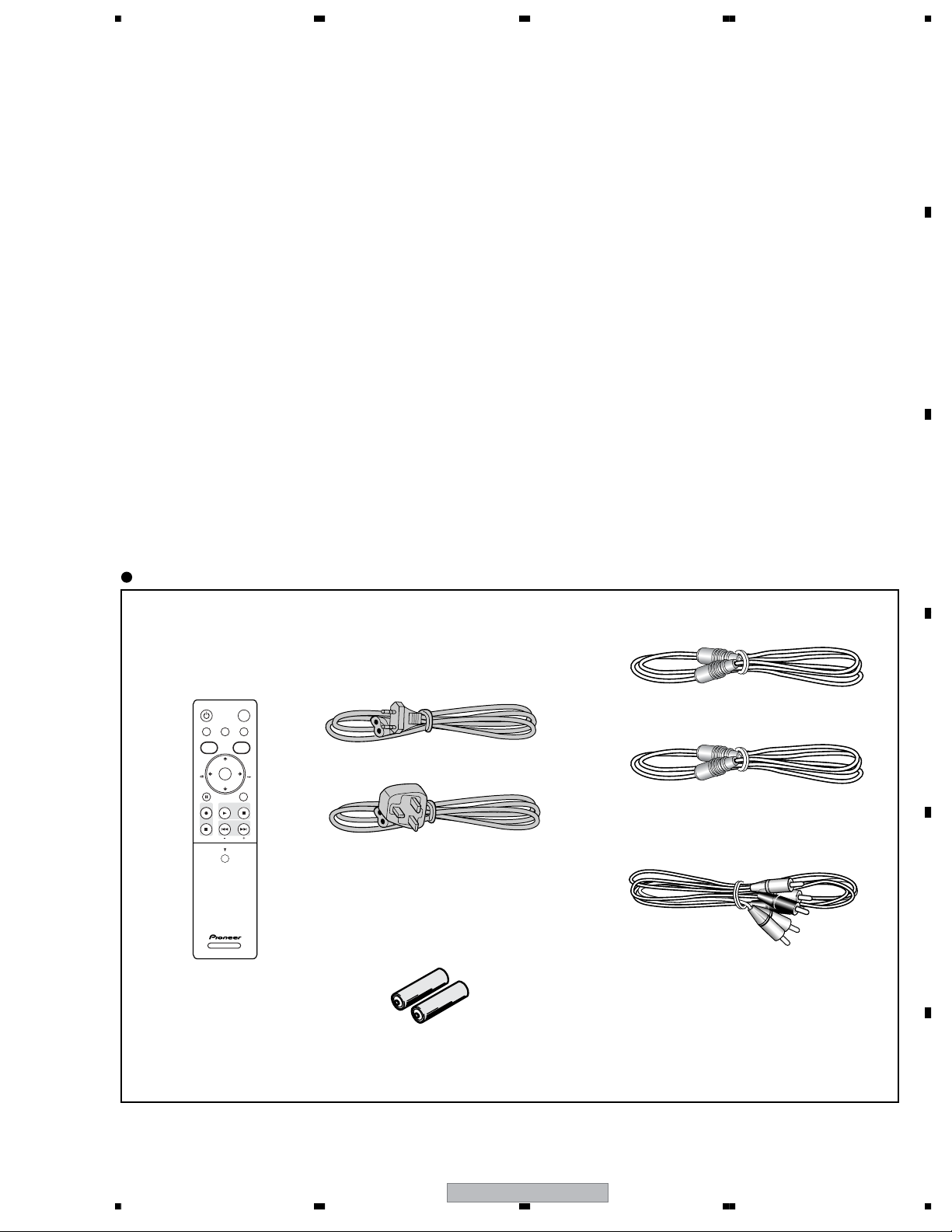
Accessories
• Remote control ×1
(VXX3092)
• RF antenna cable(PAL) ×1
(VDE1096) 30cm
• RF antenna cable(PAL) ×1
(VDE1075)
• Power cable ×1
(ADG1127 : WYXK5 types)
• Audio / Video cable(1.5m) ×1
(red/white/yellow)
(VDE1077)
• G-Link Cable (3m) ×1
(VDX1010)
• Dry cell batteries ×2
(AA/R6P)
DVD RECORDER
OPEN
STANDBY/ON
HOME MENU INFOPAUSE LIVE TV
ENTER
PREV NEXT
STOP REC
PLAYREC STOP
TOP MENU
DISC
NAVIGATOR
GUIDE
CM
SKIP
CM
BACK
PAUSE RETURN/EDIT
CHANNEL
HDD/DVD
(ADG7077 : WVXK/5, WVXK5 types)
1.5m
DVR-540HX-S
8
1234
1234
C
D
F
A
B
E
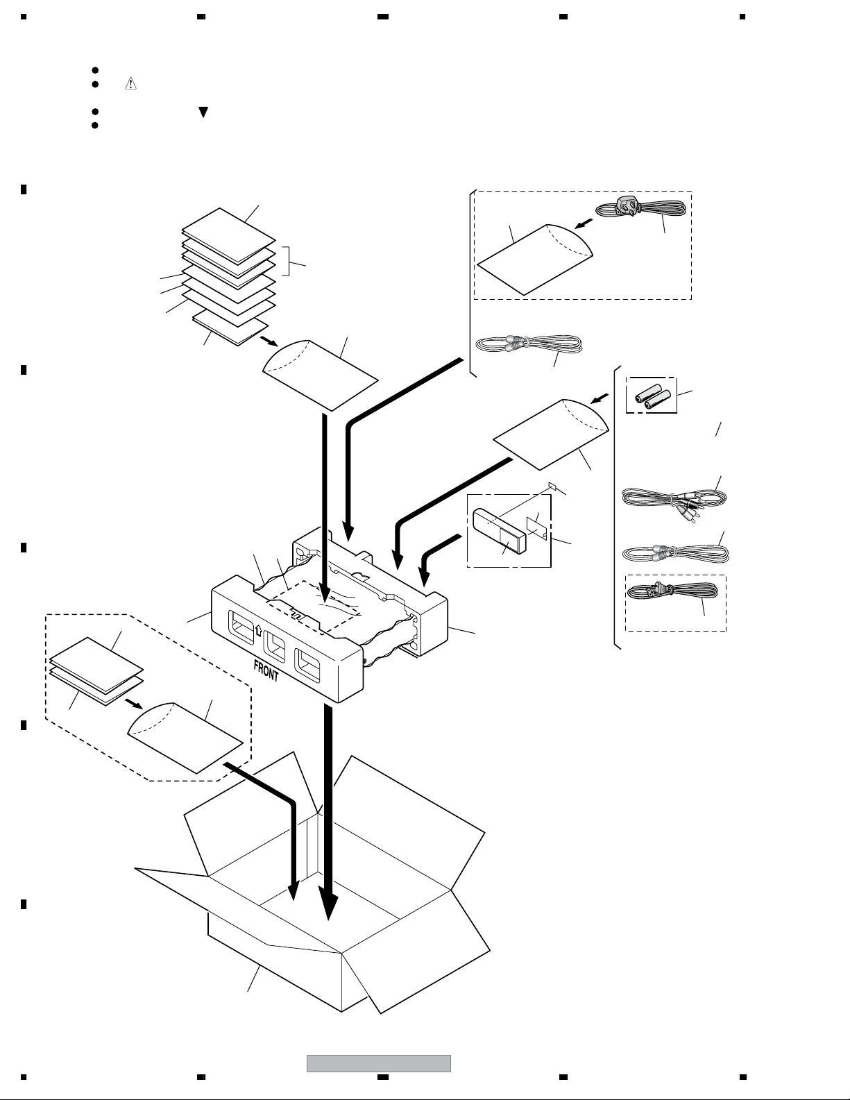
2. EXPLODED VIEWS AND PARTS LIST
2.1 PACKING
Parts marked by "NSP" are generally unavailable because they are not in our Master Spare Parts List.
The mark found on some component parts indicates the importance of the safety factor of the part.
Therefore, when replacing, be sure to use parts of identical designation.
Screws adjacent to mark on product are used for disassembly.
For the applying amount of lubricants or glue, follow the instructions in this manual.
(In the case of no amount instructions, apply as you think it appropriate.)
NOTES:
23
25
24
19
19
WYXK5 only
for WYXK5
for WVXK/5 and WVXK5
5
9
8
3
6
7
19
26
17
22
2
1
1
1
4
15
16
19
10
(WYXK5 only)
(WVXK/5 and WVXK5 only)
18
11
12 to 14
28
27
DVR-540HX-S
9
5678
56
7
8
C
D
F
A
B
E
(1) PACKING SECTION PARTS LIST
(2) CONTRAST TABLE
DVR-540HX-S/WYXK5, WVXK/5 and DVR-440HX-S/WVXK5 are constructed the same except for the following:
Mark
No. Description Part No.
>
1Power Cord See Contrast table (2)
2 RF Antenna Cable (PAL) VDE1075
3Audio/Video Cable (1.5m) VDE1077
4 RF Antenna Cable (PAL) VDE1096
5 Remote Control Unit VXX3092
6 Battery Cover VZN1004
7Top Cover VZN1009
NSP 8 Dry Cell Battery (R6P, AA) VEM1010
9 WEEE Label VRW2231
NSP 10 Warranty Card ARY7065
11 Operating Instructions (English) See Contrast table (2)
12 Operating Instructions (French) See Contrast table (2)
13 Operating Instructions
(German)
See Contrast table (2)
14 Operating Instructions (Italian) See Contrast table (2)
15 Operating Instructions
(Spanish)
See Contrast table (2)
16 Operating Instructions (Dutch) See Contrast table (2)
NSP 17 HDD Caution 8L B VRR1046
NSP 18 HDD Caution 8L VRR1047
19 Polyethylene Bag B5 VHL1051
20 • • • • • • •
21 • • • • • • •
22 G-Link Cable VDX1010
23 Front Pad VHA1408
24 Rear Pad VHA1409
25 Packing Case See Contrast table (2)
26 Mirror Sheet VHL1107
27 PLTV Caution VRR1068
28 DTV Time Caution VRR1069
Mark No. Symbol and Description
DVR-540HX-S
/WYXK5
DVR-540HX-S
/WVXK/5
DVR-440HX-S
/WVXK5
>
1Power Cord ADG1127 ADG7077 ADG7077
11 Operating Instructions (English) Not used VRB1439 VRB1439
12 Operating Instructions (French) VRC1334 Not used Not used
13 Operating Instructions (German) VRC1335 Not used Not used
14 Operating Instructions (Italian) VRC1336 Not used Not used
15 Operating Instructions (Spanish) VRC1337 Not used Not used
16 Operating Instructions (Dutch) VRC1338 Not used Not used
25 Packing Case VHG2712 VHG2754 VHG2713
DVR-540HX-S
10
1234
1234
C
D
F
A
B
E
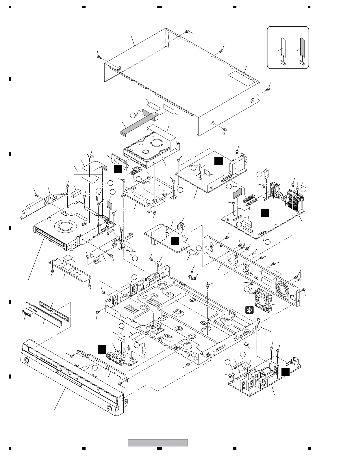
2.2 EXTERIOR SECTION
A
A
B
C
D
D
E
E
F
F
G
H
I
I
J
J
K
K
H
G
C
B
B
CONTACT SIDE
NON-CONTACT
SIDE
D
C
A
H
I
1
2
4
14
18
20
22
24
25
26
23
17
10
32
19
21
8
11
38
44
44
44
44
44
42
42
42
42
42
42
42
42
42
42
42
42
42
42
42
42
42
44
44
44
44
44
44
44
44
44
43
43
43
46
43
41
42
46
46
46
13
27
34
39
39
39
39
39
40
33
29
30
41
41
39
31
35
37
36
32
28
45
12
16
9
6
5
7
3
15
Refer to
"2.4 FRONT PANEL SECTION".
Refer to
"2.3 SERVICE LOADER MAIN".
Cleaning paper
GED-008

DVR-540HX-S
11
5678
56
7
8
C
D
F
A
B
E
(1) EXTERIOR SECTION PARTS LIST
(2) CONTRAST TABLE
DVR-540HX-S/WYXK5, WVXK/5 and DVR-440HX-S/WVXK5 are constructed the same except for the following:
Mark
No. Description Part No.
1JACB Assy VWV2230
2 ATAB Assy VWV2231
3 FRJB Assy VWV2232
4 DTBR Assy VWV2228
5 TUNB Assy VWV2229
NSP 6 Service LOADER MAIN VXU1002
>
7POWER SUPPLY Unit VWR1403
8 HDD See Contrast table (2)
9 Housing Assy (4P) VKP2357
10 Connector Assy (13P) PF13PP-S42
11 Flexible Cable (40P) VDA2136
12 Flexible Cable (10P) VDA2137
13 Flexible Cable (35P) VDA2138
14 Flexible Cable (19P) VDA2141
15 Flexible Cable (26P) VDA2140
16 Ferrite Core VTH1057
17 DC Fan Motor 60 VXM1125
18 PCB Support AEC1215
19 Rubber Foot VEB1349
20 Rear Panel See Contrast table (2)
NSP 21 Chassis VNB1055
NSP 22 PCB Stay VNE2399
NSP 23 Bridge VNE2429
24 Earth Plate TU VBK1156
25 Earth Spring VBK1161
26 Radiation Sheet (Silicone) VEB1360
27 Rubber Spacer VEB1378
NSP 28 HDD Stay VNE2423
29 Writer Stay L VNE2433
30 Writer Stay R VNE2434
31 Heatsink VNH1077
NSP 32 Binder (BK-1) ZCA-BK1
33 Gasket 30 x 10T VEC2522
34 Aluminum Tape 150 x 25 VEF1061
35 Pioneer Name Plate VAM1148
36 Tray Sheet VEC2500
37 Tray Panel VNK5910
38 Bonnet Case S VXX3169
NSP 39 Tape ZTA-156A-19
40 Laser Caution Label VRW2262
41 Screw AMZ30P040FTC
42 Screw BBZ30P060FTC
43 Screw BPZ30P080FTC
44 Screw BSZ30P040FTC
45 #6-32 Screw DBA1125
46 Screw PBZ30P080FTC
Mark
No. Description Part No.
Mark No. Symbol and Description
DVR-540HX-S
/WYXK5
DVR-540HX-S
/WVXK/5
DVR-440HX-S
/WVXK5
8 HDD 160G ST3160022RS VXF1086 VXF1086 Not used
8 HDD 80G ST380012R SV Not used Not used VXF1084
20 Rear Panel VNA2864 VNA2864 VNA2904
DVR-540HX-S
12
1234
1234
C
D
F
A
B
E
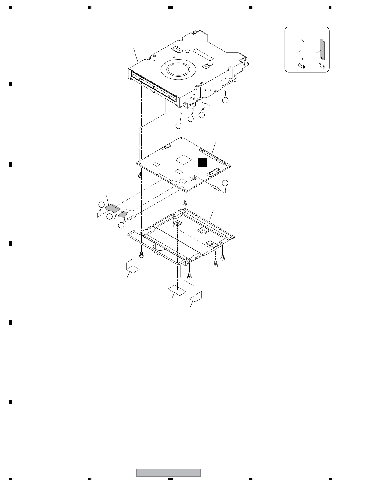
2.3 SERVICE LOADER MAIN
SERVICE LOADER MAIN PARTS LIST
D
D
C
C
B
B
A
A
CONTACT SIDE
NON-CONTACT
SIDE
G
Reuse (*) marked
parts when exachanging
Service LOADER
Assy.
(*)
(*)
(*)
(*)
(*)
(*)
(*)
• Silicon Sheet R9B
(DEB1726) x3
• Case Screw S
(DBA1250) x2
• Frontboard Screw
R7C
(DBA1220) x2
1
5
3
2
5
5
4
Mark
No. Description Part No.
1 MAIN Assy (for service) VXX3159
2LOADER Assy (for service) VXX3156
3Low Case U11 DNC1761
4 FFC U11 DDX1208
NSP 5 Tape ZTA-156A-19
DVR-540HX-S
14
1234
1234
C
D
F
A
B
E
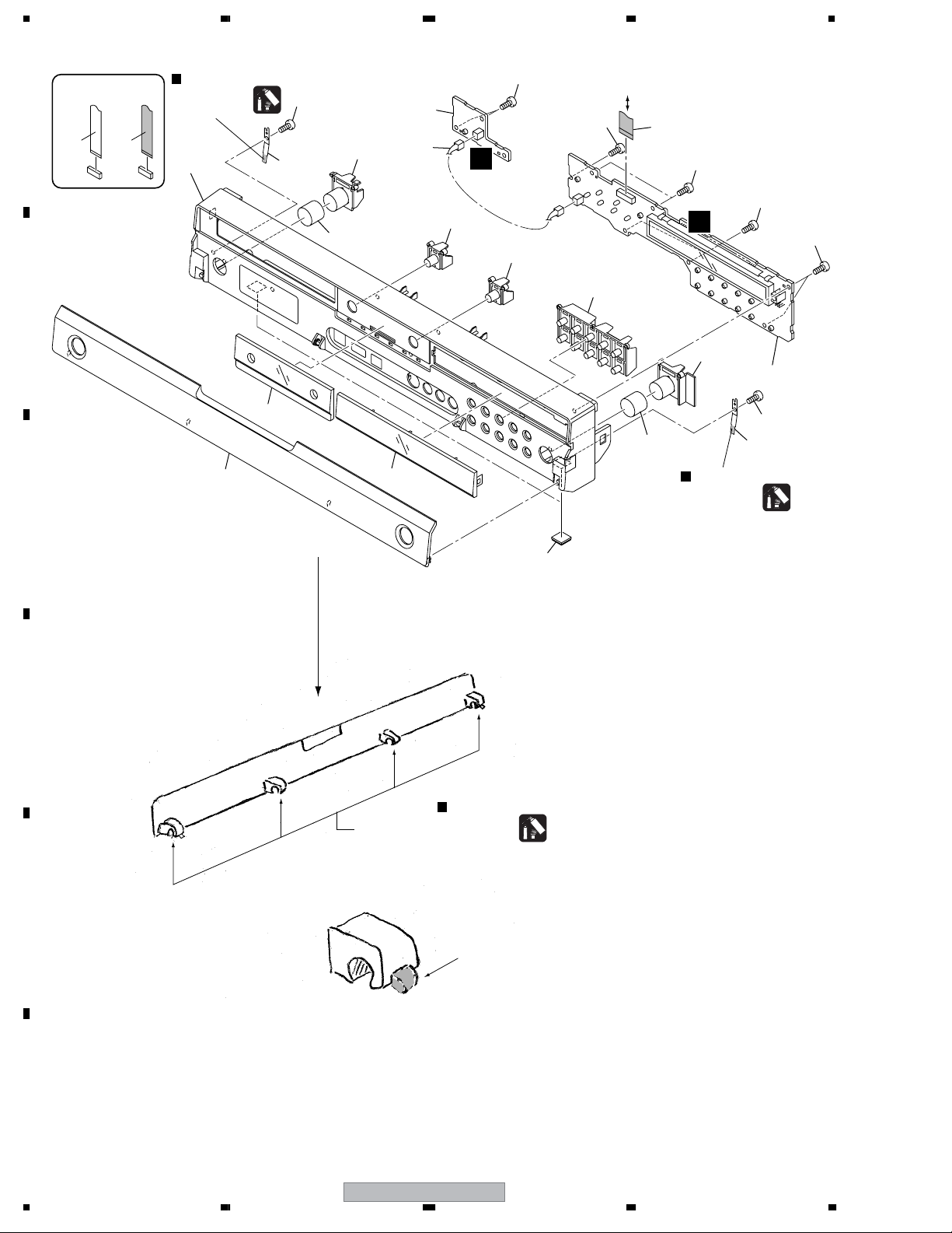
2.4 FRONT PANEL SECTION
FRJB
CN302
CONTACT SIDE
NON-CONTACT
SIDE
E
F
15
15
5
3
4
7
11
15
15
1
2
5
15
15
15
12
9
10
8
(1/4)
8
(2/4)
8
(3/4)
8
(4/4)
14
13
6
Hanarl
GEM1041
Lubricant
Hanarl
GEM1041
Lubricant
Hanarl
GEM1041
Lubricant
Door Shaft
to Door Shaft
Paste lubricant hanarl (GEM1041)
to salient points of both side of the
door.

DVR-540HX-S
15
5678
56
7
8
C
D
F
A
B
E
(1) FRONT PANEL SECTION PARTS LIST
(2) CONTRAST TABLE
DVR-540HX-S/WYXK5, WVXK/5 and DVR-440HX-S/WVXK5 are constructed the same except for the following:
Mark
No. Description Part No.
1 FLKY Assy VWG2571
2 PWSB Assy VWG2572
3 Flexible Cable (14P) VDA2139
4 Housing Assy (2P) VKP2382
5 Door Spring VBK1159
6 Rubber Foot VEB1349
7 Main Key VNK5937
8Key Base VNK5938
9Key Top P VNK5939
10 Key Top R VNK5940
11 Center Lens VNK5941
12 Front Panel VNK5951
13 FL Lens PTD See Contrast table (2)
14 Door PTD See Contrast table (2)
15 Screw BPZ30P080FTC
Mark No. Symbol and Description
DVR-540HX-S
/WYXK5
DVR-540HX-S
/WVXK/5
DVR-440HX-S
/WVXK5
13 FL Lens PTD VXA2742 VXA2742 VXA2798
14 Door PTD VXA2769 VXA2770 VXA2770
DVR-540HX-S
16
1234
1234
C
D
F
A
B
E
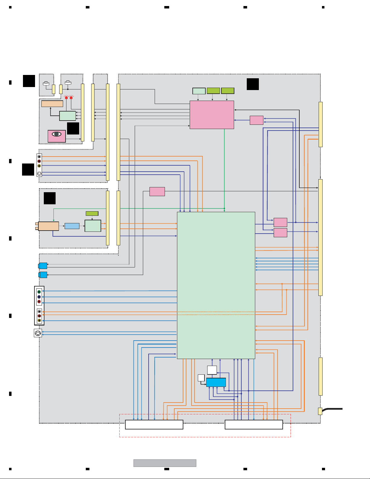
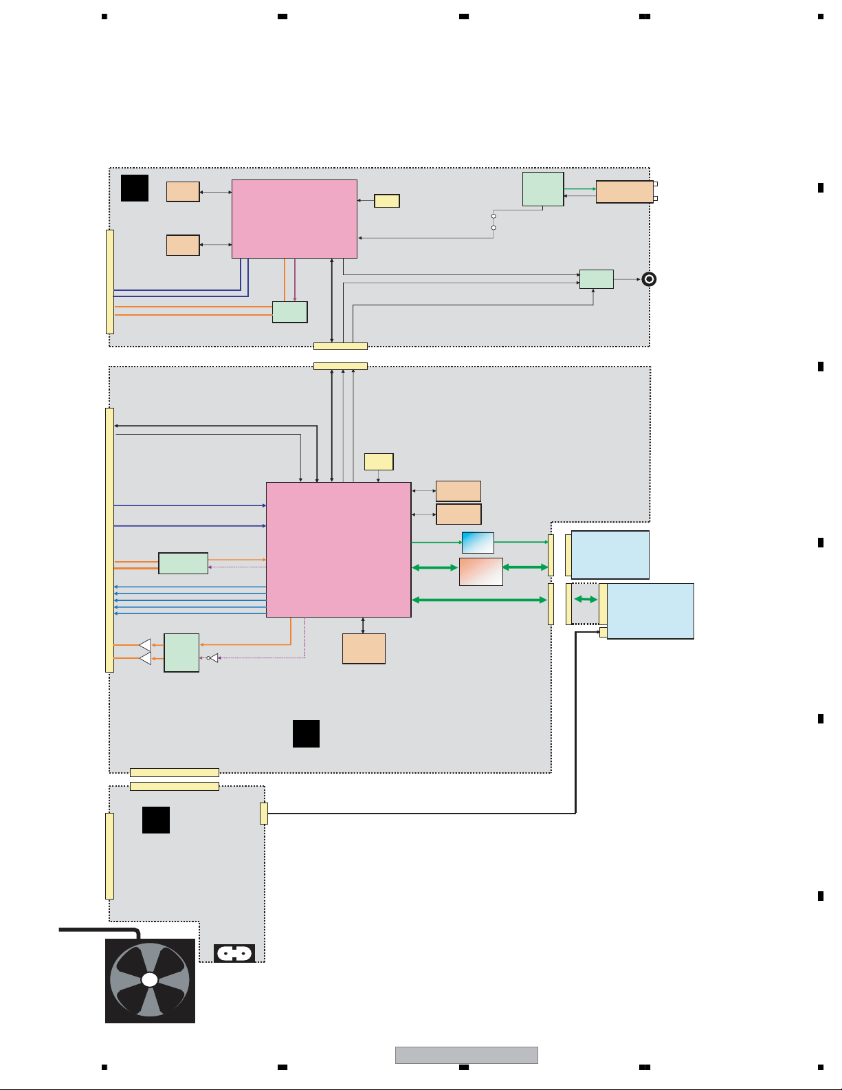
3. BLOCK DIAGRAM AND SCHEMATIC DIAGRAM
3.1 BLOCK DIAGRAM
3.1.1 OVERALL BLOCK DIAGRAM
HA118326
(Renesas)
Audio/Video SW&Driver
CVBS : 5in-1out,
Y&C : 3in-1out
Include
Y/C MIX,
RGB/YCbCr SW & MUTE,
SCART SW.
Without
Audio Electronic Volume
Connecting idea(25 Apr):
L1in:AV1(CVBS),Digi-TU(Y/C)
L2in:Line2
L3in:AV2(V/Y),(RGB→YC)
Icc(5V+9V):
Icc(5V+9V):
104mA(Min)
104mA(Min)
130mA(Typ)
130mA(Typ)
156mA(Max)
156mA(Max)
SCL/SDA
15MHz
RESET IC
FLSTB
V/Y to MAIN
32k
L toMAIN
R toMAIN
AR Out
AL Out
G Out
B Out
R/C Out
C Out
Y Out
R/C
C toMAIN
TU_RIN (Ana-TU)
TU_RIN (Ana-TU)
AR
AL
VV/Y AL
AR
VV/Y
BG
BR/C G
AV2 (from STB)
AV1 (to TV)
TU_VIN (Ana-TU)
TU_VIN (Ana-TU)
FLCLK
FLDATA
TEXTV
FL DRIVER
PT6315
FL TUBE
IR
SEL_IR
DTU_CIN(Digi-TU)
DTU_YIN (Digi-TU)
Tuner Control µCON
LC87F05J2A
RGB → Y/C
CONVERT
Cb/B Out
Cr/R Out
Y/G Out
AV1_V/YIN(AV1)
AV1_LIN(AV1)
AV1_RIN(AV1)
DTU_LIN(Digi-TU)
DTU_LIN(Digi-TU)
DTU_RIN(Digi-TU)
DTU_RIN(Digi-TU)
R/C IN
G IN
B IN
RGB_CIN
AV2_V/YIN(AV2)
AV2_LIN(AV2)
AV2_RIN(AV2)
AR
AL
AL
AR
45
46
44
16
30 74 73 72 71 100 1
49
48 50
12
22
90
89
94
93
76
77
53
52
51
57
55
59
61
79
80
18
86
87
43/42
C Out
Y Out
36
34
Y
C
COMPONENT
OUT
Cb Out
Cb Out
Cr Out
Cr Out
Y Out
Y Out
40
38
39
CY
Cb
Cr
OUTPUT
V(YC MIX) Out
V(YC MIX) Out
32
V
AL
AR
V2
V2
Y2
Y2
C2
C2
1479
R2
R2
L2
L2
9291
G-Link
SR in
IR
SEL_IR
SCL/SDA
SIF
VHF/UHF Tuner
4.5~6.7MHz
SIF BPF
18.432M
Multi
Sound
DECODER
MSP3417
TU_LIN (Ana-TU)
TU_LIN (Ana-TU)
Y2
C2
INPUT2
V2
L2
R2
Key
LED
Key Matrix
AV1_V/YOUT(AV1)
AV1_LOUT
AV1_ROUT
AV2_LOUT
AV2_ROUT
RGB_YIN
AV2_V/YOUT(AV2)
84
85
13
19 2620
71115 13
19 2620
71115
S OUT
BLASTER IR
µCON
PDF015A-K
VIDEO
SW
MM1503XN
VIDEO
SW
MM1501XN
4.43
MHz
IR Receiver
IN
OUT
VIDEO
SW
MM1503XN
FRJB
SW
for
Line23
A
JACB ASSY
B
TUNB ASSY
D
FRJB
ASSY
F
PWSB ASSY
E
FLKY
ASSY
DVR-540HX-S
17
5678
56
7
8
C
D
F
A
B
E
EMMA2RFE
DDR SDRAM
512Mbit
DDR SDRAM
512Mbit
Y
C
Y/G
Cb/B
Cr/R
SW
AMCK : 33/36M
ADCCLKO
COAXIAL
HDD
80GB (440HX)
160GB (540HX)
ATAB
DAC
PCM1742
L
R
Euro Digita
Terrestrial
Tuner
EMMMA2LL
SPDIFI
27MHz
LRCKI/BCKI/ADATAI
OFDM DEM IC
STV0361
SDRAM
256Mbit
Flash
32Mbit
A/D
PCM1802
27MHz
MPEG2-TS
SCL/SDA
AGC
DAC
PCM1742
LRCKO
BCKO
ADATAO
UART/(RESET)
LRCKO
BCKO
ADATAO
AMCK
GPIO
Optical Signal SW
SPDIFI
FAN
LOADER
TXDGL
RXDGL
IN
OUT
DRV IC
BD799
RF IC
UPC3345GC
-YEB
Flash
64Mbit
C
DTBR ASSY
G
MAIN ASSY
I
POWER SUPPLY
UNIT
DVR-540HX-S
18
1234
1234
C
D
F
A
B
E
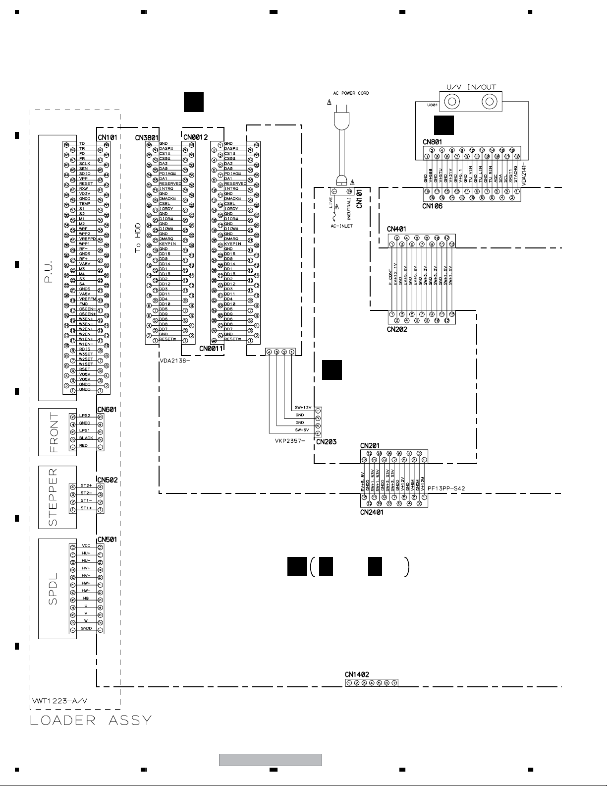
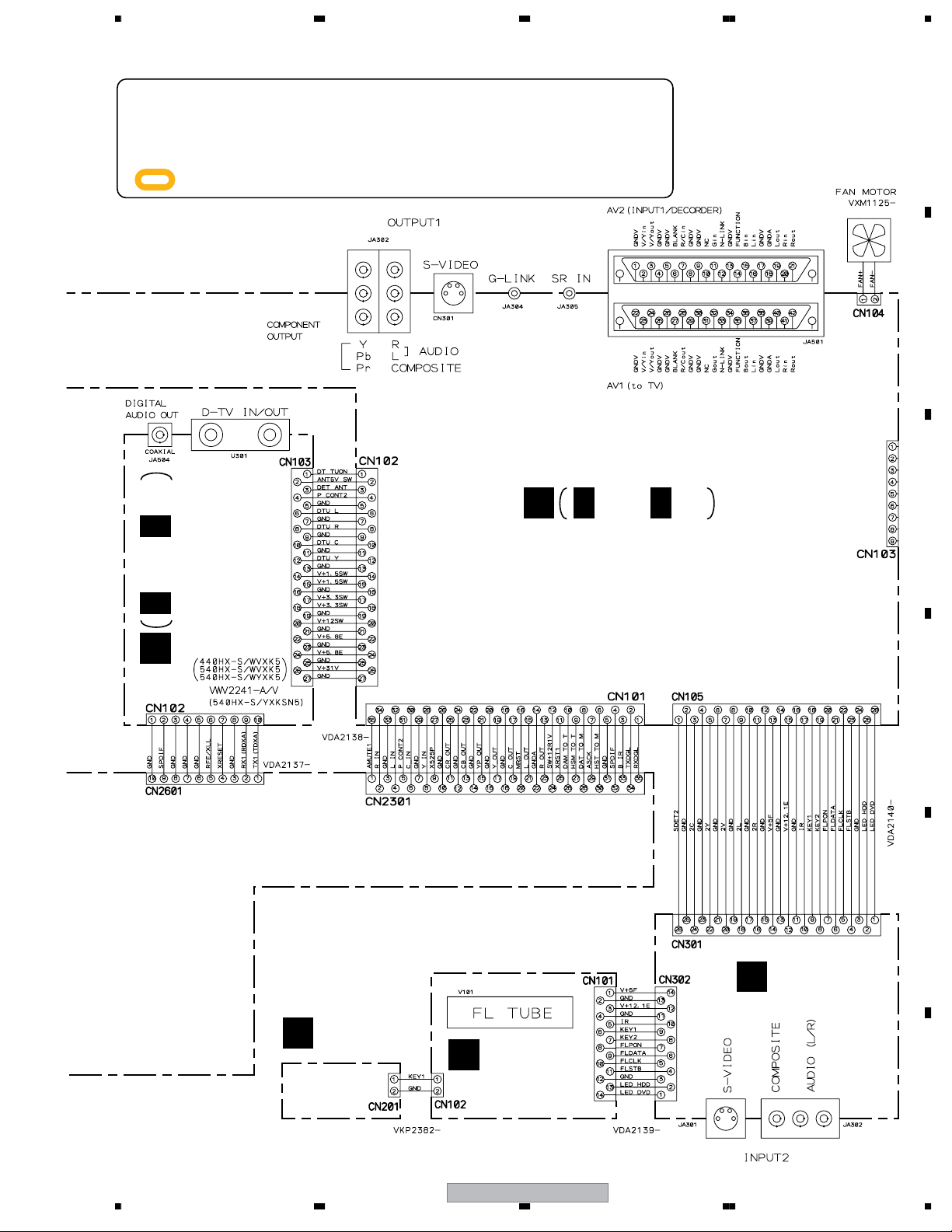
3.2 OVERALL WIRING DIAGRAM
H
ATAB ASSY
(VWV2231)
HDD (160GB : DVR-540HX-S)
(80GB : DVR-440HX-S)
I
POWER SUPPLY UNIT
(VWR1403)
B
TUNB ASSY
(VWV2229)
MAIN ASSY (VXX3159)
G 1/3– G 3/3
G
DVR-540HX-S
19
5678
56
7
8
C
D
F
A
B
E
F
PWSB ASSY
(VWG2572)
E
FLKY ASSY
(VWG2571)
D
FRJB ASSY
(VWV2232)
JACB ASSY (VWV2230)
A 1/3– A 3/3
A
C 1/2– C 2/2
C
DTBR ASSY
(VWV2228)
÷
When ordering service parts, be sure to refer to "EXPLODED VIEWS and PARTS
LIST" or "PCB PARTS LIST".
÷
The > mark found on some component parts indicates the importance of the safety
factor of the part. Therefore, when replacing, be sure to use parts of identical
designation.
÷
: The power supply is shown with the marked box.
DVR-540HX-S
20
1234
1234
C
D
F
A
B
E
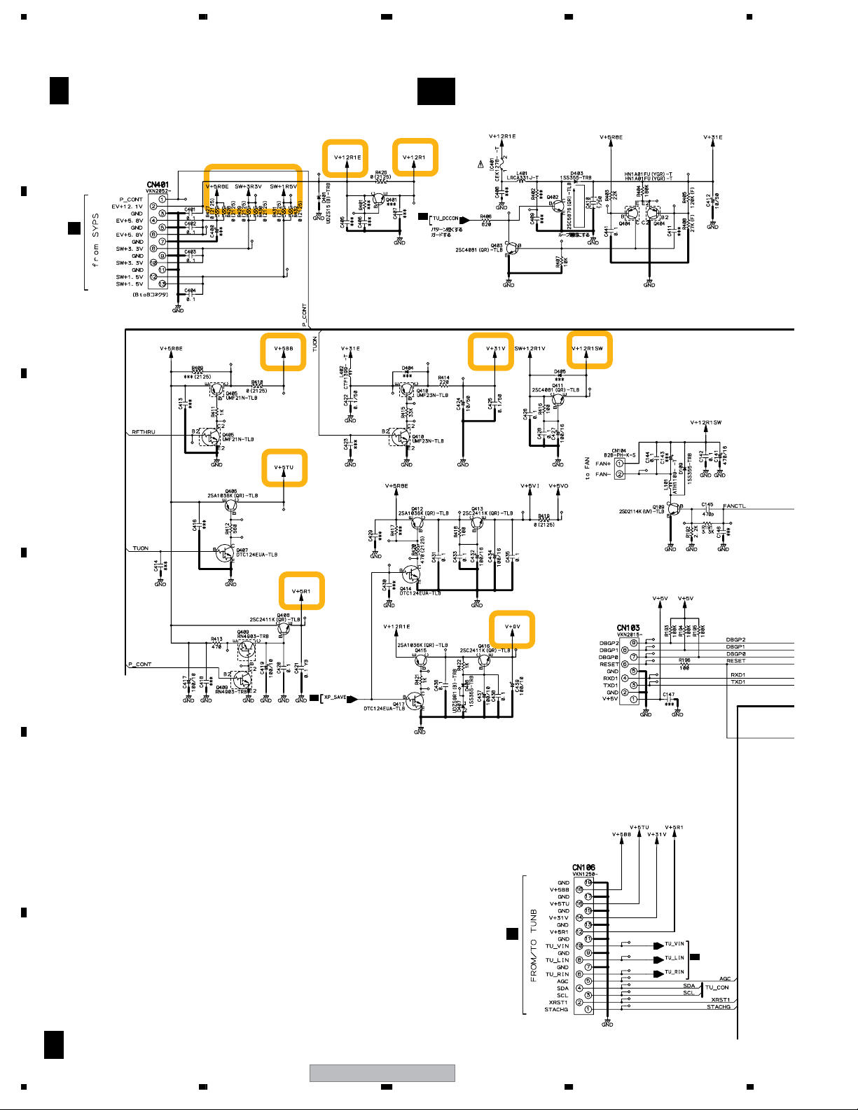
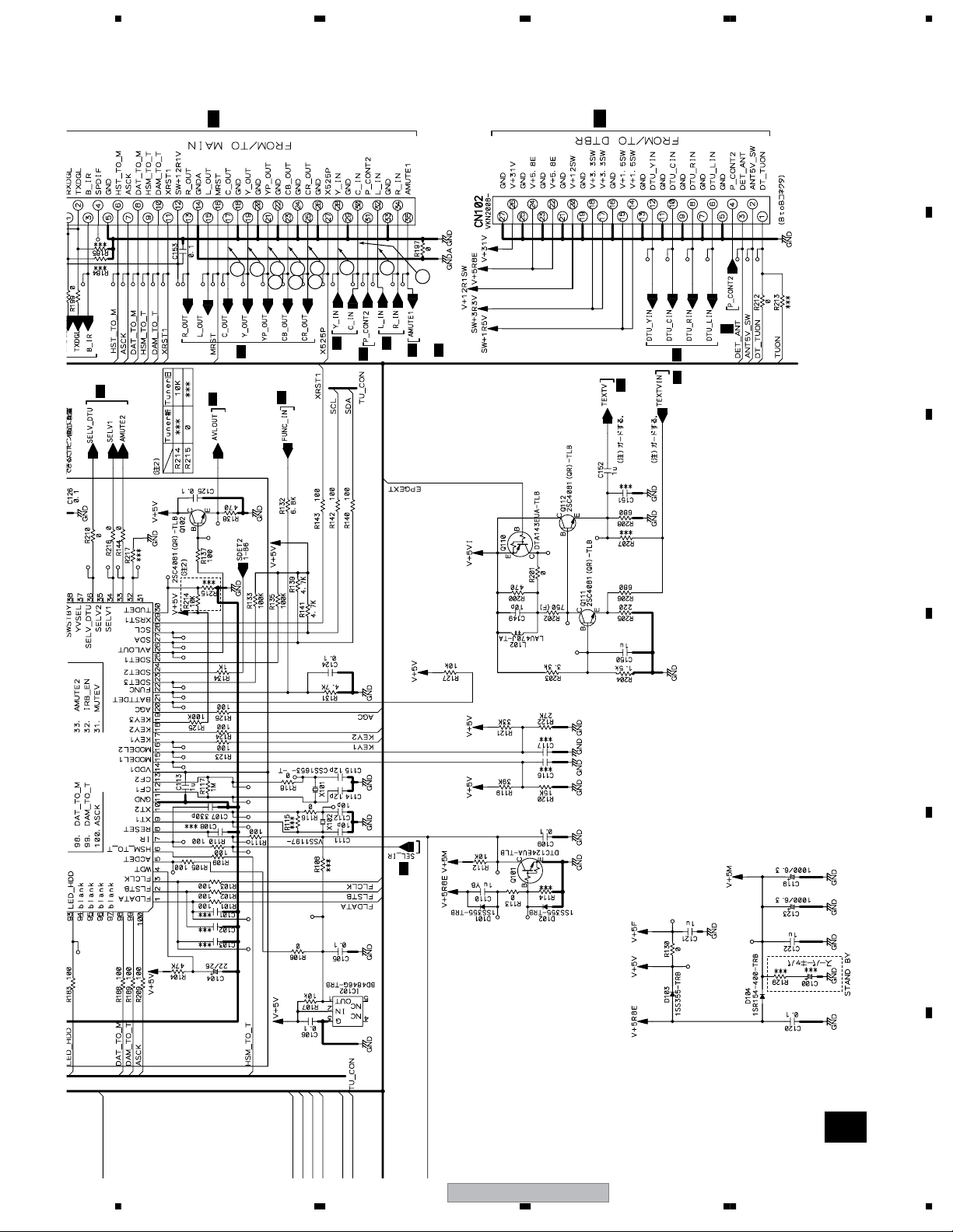
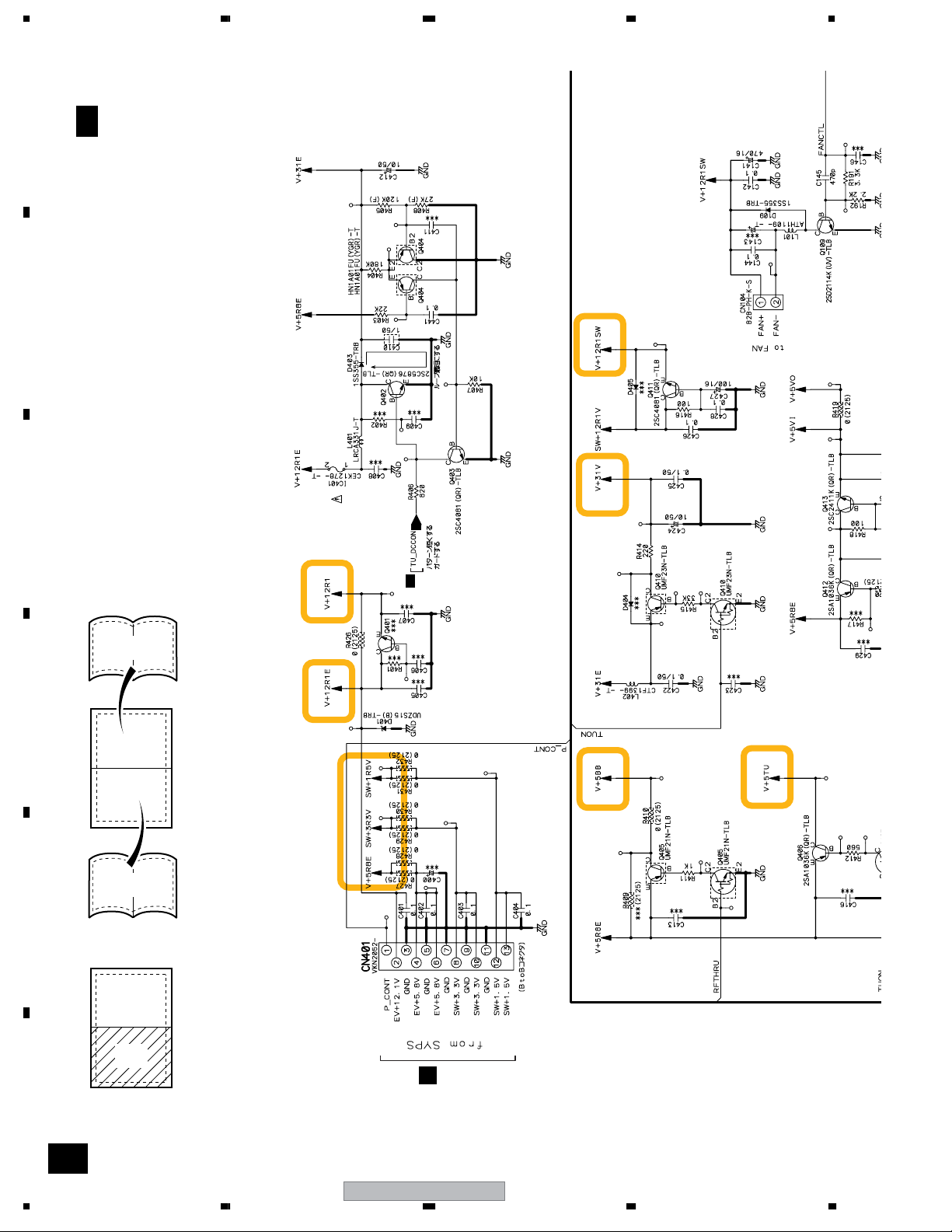
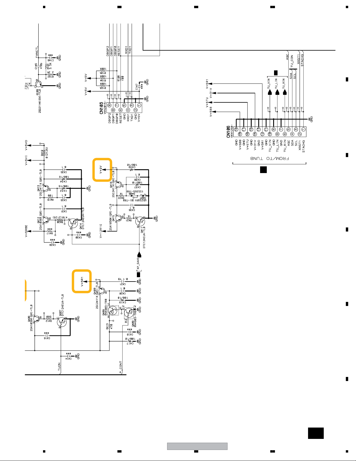
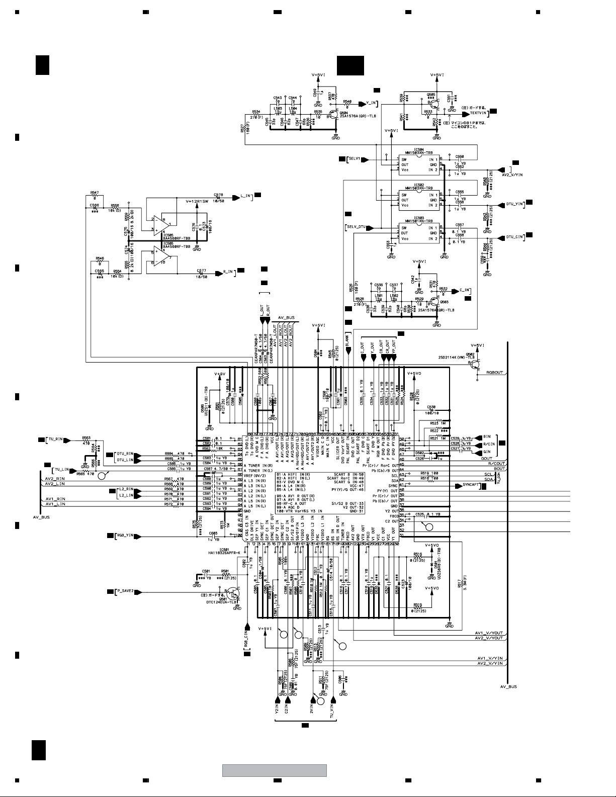
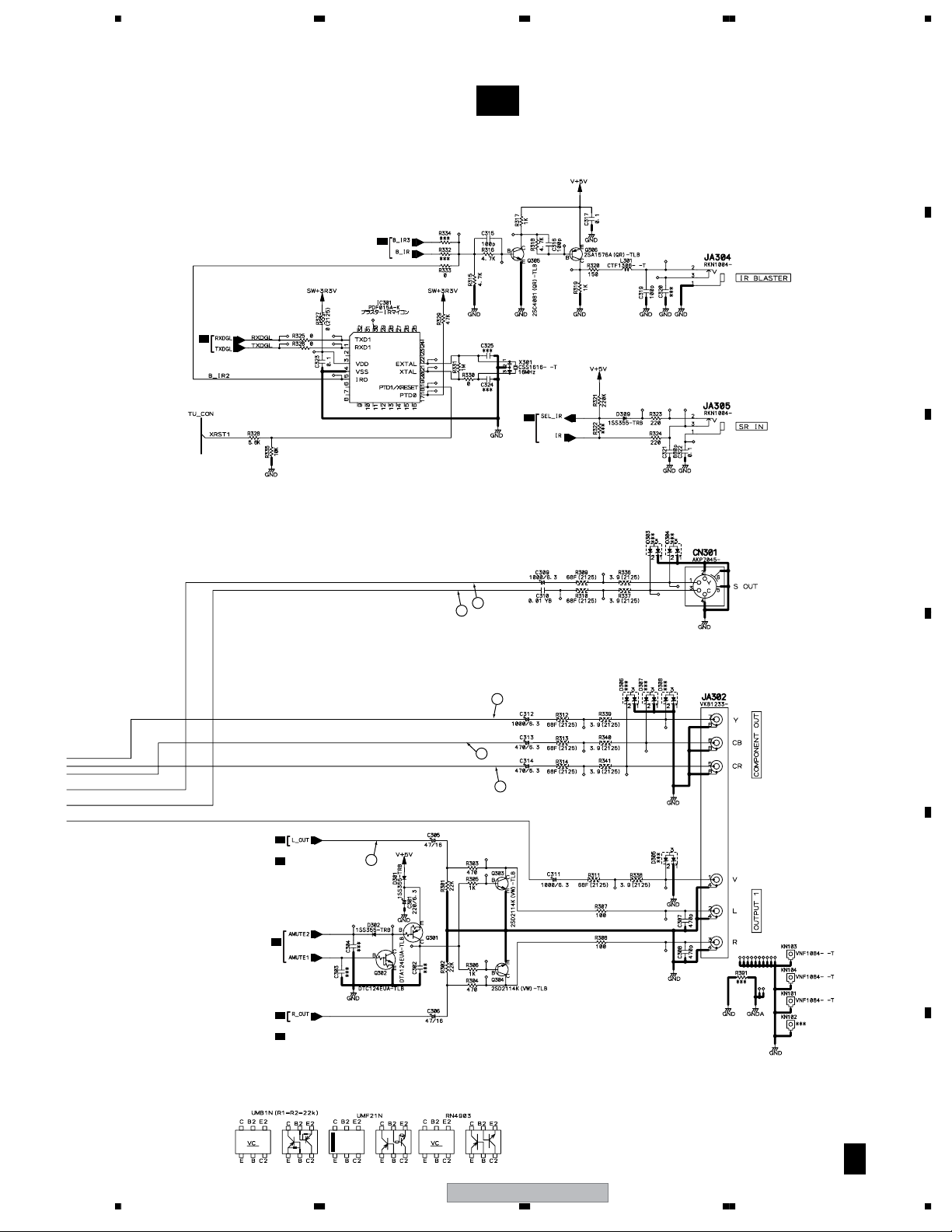
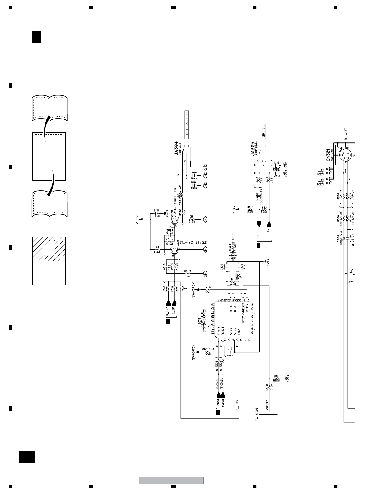
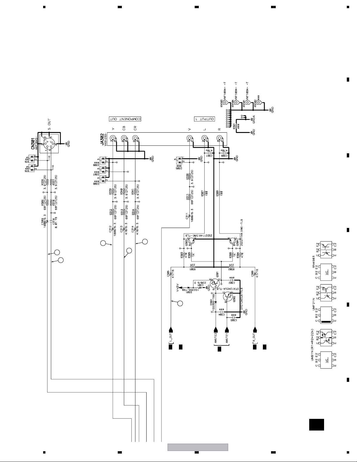
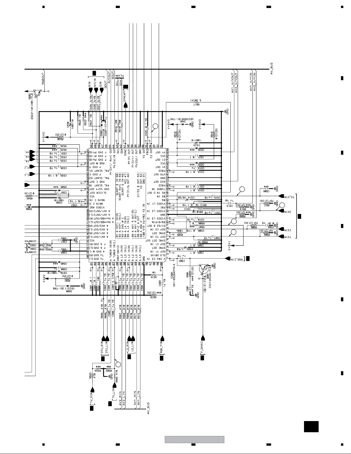
3.3 JACB ASSY (1/3)
CN202
I
CN801
B
A 2/3
A 1/3
A 1/3
A 1/3
A-b
A 1/3
JACB ASSY (VWV2230)
DVR-540HX-S
21
5678
56
7
8
C
D
F
A
B
E
CN301
D
A 2/3
A 1/3
A 2/3
A 2/3 A 2/3
A 2/3
A 1/3
A 1/3, A 2/3
A 2/3
A 2/3
A 1/3
A 2/3
A 1/3
A 3/3
A 3/3
A 2/3
A 3/3
A 3/3
A 2/3A 1/3
A 3/3
A 1/3
A 1/3, A 2/3
A 1/3
A 1/3
A 2/3
A 1/3
A 2/3, A 3/3
A
1/3
A 2/3
1/2
CN103
C
3/2
CN2301
G
23
20
19
12
15
11
14
10
8
9
13
A-a
A 1/3
DVR-540HX-S
22
1234
1234
C
D
F
A
B
E
A-a
A-b
A-a
Large size
SCH diagram
CN301
D
A 1/3
A-a 1/3
JACB ASSY (VWV2230)
A 2/3
A 1/3
A 2/3
A 2/3
A 3/3
A 2/3
A 3/3
A 2/3A 1/3
A 3/3
A 1/3
A 1/3, A 2/3
A 1/3
A 1/3
A 2/3
A 1/3
A 2/3, A 3/3
A
1/3
DVR-540HX-S
23
5678
56
7
8
C
D
F
A
B
E
A-a 1/3
A 2/3
A 2/3
A 1/3
A 1/3, A 2/3
A 2/3
A 2/3
A 1/3
A 2/3
A 1/3
A 3/3
A 2/3
A 3/3
A 2/3
1/2
CN103
C
3/2
CN2301
G
23
20
19
12
15
11
14
10
8
9
13
DVR-540HX-S
24
1234
1234
C
D
F
A
B
E
A-a
A-b
A-b
Large size
SCH diagram
CN202
I
A-b 1/3
A 1/3
JACB ASSY (VWV2230)
A 1/3
DVR-540HX-S
25
5678
56
7
8
C
D
F
A
B
E
CN801
B
A-b 1/3
A 2/3
A 1/3
DVR-540HX-S
26
1234
1234
C
D
F
A
B
E
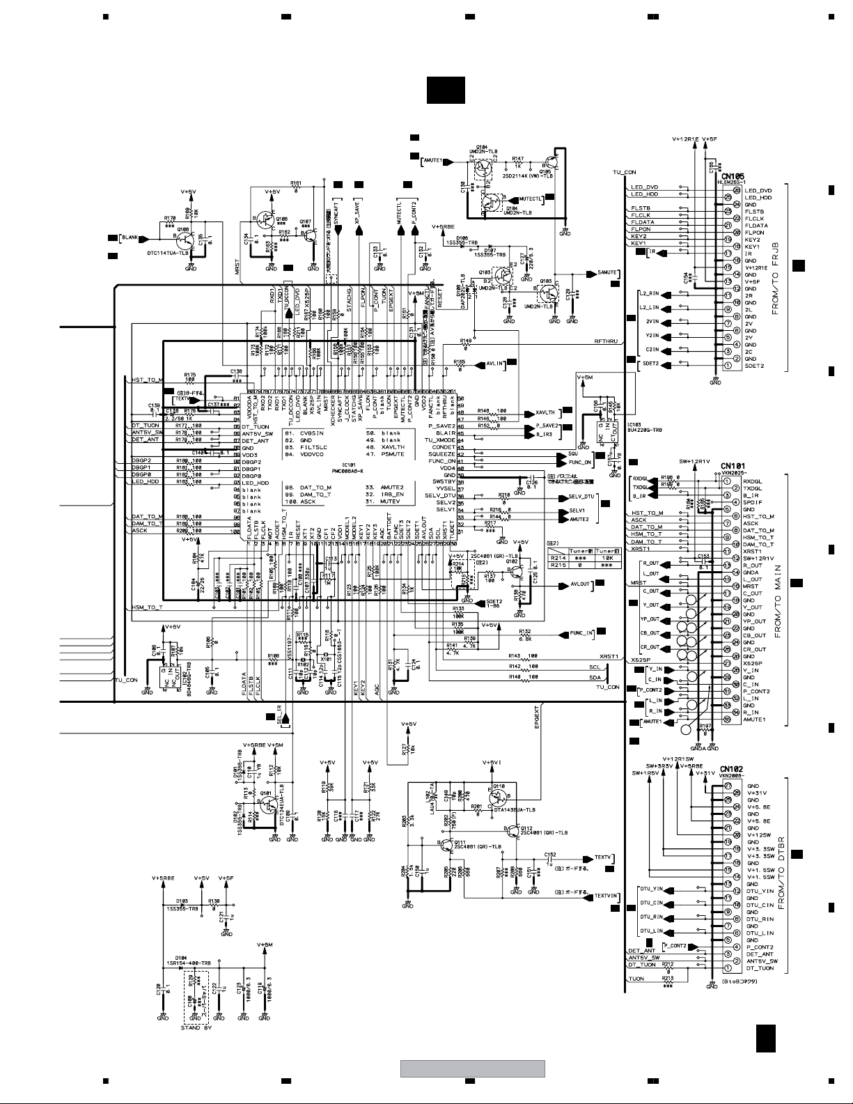
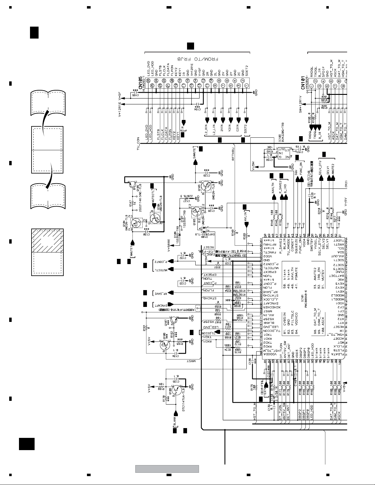
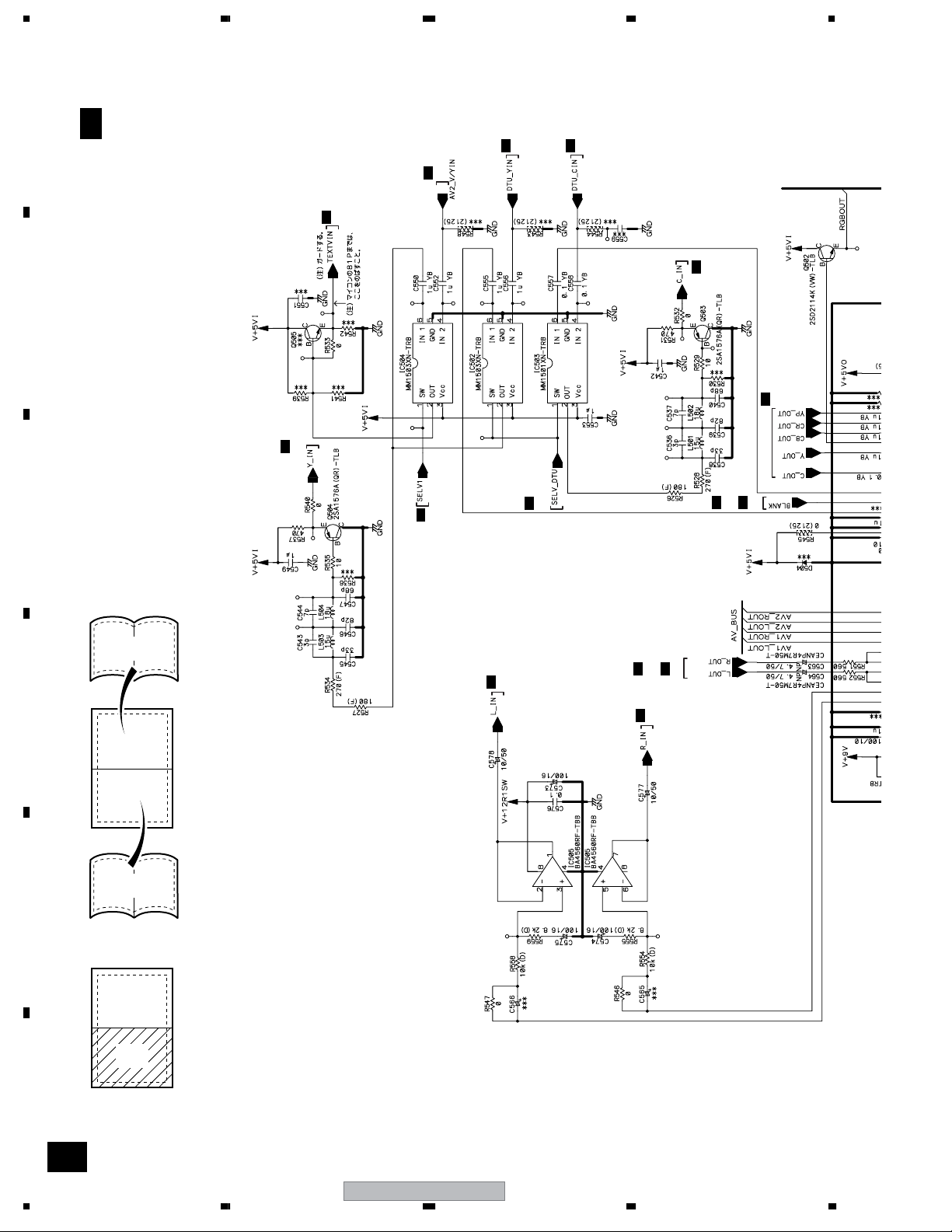
3.4 JACB ASSY (2/3)
A 3/3
A 1/3
A 1/3
A 3/3
A 1/3
A 3/3
A 1/3
A 1/3
A 1/3
A 1/3
A 1/3, A 2/3
A 1/3
A 1/3
A 1/3
A 3/3
A 1/3 A 1/3
A 1/3
A 1/3
A 1/3, A 3/3
A 1/3
A 1/3
A 1/3
21
17
18
1
3
16
A 2/3
A-d
A 2/3
JACB ASSY (VWV2230)
DVR-540HX-S
27
5678
56
7
8
C
D
F
A
B
E
A 1/3
A 1/3
A 1/3, A 2/3
A 1/3
A 1/3, A 2/2
A 1/3
5
2
4
7
22
6
A-c
A 2/3
DVR-540HX-S
28
1234
1234
C
D
F
A
B
E
A-c
A-d
A-c
Large size
SCH diagram
A 2/3
JACB ASSY (VWV2230)
A 1/3
A 1/3
A 1/3
2
A-c 2/3
DVR-540HX-S
29
5678
56
7
8
C
D
F
A
B
E
A 1/3, A 2/3
A 1/3
A 1/3, A 2/2
5
2
4
7
22
6
A-c 2/3
DVR-540HX-S
30
1234
1234
C
D
F
A
B
E
A-c
A-d
A-d
Large size
SCH diagram
A 2/3
JACB ASSY (VWV2230)
A 1/3, A 2/3
A 1/3
A 1/3
A 1/3
A 3/3
A 1/3 A 1/3
A 1/3
A 1/3
A 1/3, A 3/3
A 1/3
A 1/3
A 1/3
A-d 2/3
DVR-540HX-S
31
5678
56
7
8
C
D
F
A
B
E
A 3/3
A 1/3
A 1/3
A 3/3
A 1/3
A 3/3
A 1/3
A 1/3
A 1/3
A 1/3
21
17
18
1
3
16
A-d 2/3
Loading...