


 Loading...
ORDER NO.
RRV2959
DV-470-S
DVD PLAYER
DV-470-S
DV-470-K
THIS MANUAL IS APPLICABLE TO THE FOLLOWING MODEL(S) AND TYPE(S).
|
|
|
|
|
|
|
|
|
|
Serial No. |
Model |
Type |
Power Requirement |
Region No. |
Confirm 3rd & 4th |
||||||
|
|
|
|
|
|
|
|
|
|
alphabetical letters. |
|
|
|
|
|
|
|
|
|
|
|
DV-470-S |
WYXCN |
AC220-240V |
2 |
&&TE######$$ |
||||||
|
|
|
|
|
|
|
|
|
|
|
DV-470-S |
WYXCN/FG |
AC220-240V |
2 |
&&TE######$$ |
||||||
|
|
|
|
|
|
|
|
|
|
|
DV-470-S |
WVXCN |
AC220-240V |
2 |
&&TE######$$ |
||||||
|
|
|
|
|
|
|
|
|
|
|
DV-470-K |
WYXCN |
AC220-240V |
2 |
&&TE######$$ |
||||||
|
|
|
|
|
|
|
|
|
|
|
DV-470-K |
WYXCN/FG |
AC220-240V |
2 |
&&TE######$$ |
||||||
|
|
|
|
|
|
|
|
|
|
|
|
|
|
|
|
|
|
|
|
|
|
|
|
|
|
|
|
|
|
|
|
|
|
|
|
|
|
|
|
|
|
|
|
|
|
|
|
|
|
|
|
|
|
|
|
|
|
|
|
|
|
|
|
|
|
For details, refer to "Important symbols for good services".
PIONEER CORPORATION 4-1, Meguro 1-chome, Meguro-ku, Tokyo 153-8654, Japan
PIONEER ELECTRONICS (USA) INC. P.O. Box 1760, Long Beach, CA 90801-1760, U.S.A.
PIONEER EUROPE NV Haven 1087, Keetberglaan 1, 9120 Melsele, Belgium
PIONEER ELECTRONICS ASIACENTRE PTE. LTD. 253 Alexandra Road, #04-01, Singapore 159936
 PIONEER CORPORATION 2004
T-ZZE JUNE 2004 printed in Japan

1 |
2 |
3 |
4 |
SAFETY INFORMATION
A
This service manual is intended for qualified service technicians ; it is not meant for the casual do-it-yourselfer. Qualified technicians have the necessary test equipment and tools, and have been trainedto properly and safely repair complex products such as those covered by this manual.Improperly performed repairs can adversely affect the safety and reliability of the product and mayvoid the warranty. If you are not qualified to perform the repair of this product properly and safely, youshould not risk trying to do so and refer the repair to a qualified service technician.
WARNING !
BTHE AEL (ACCESSIBLE EMISSION LEVEL) OF THE LASER POWER OUTPUT IS LESS THAN CLASS 1 BUT THE LASER COMPONENT IS CAPABLE OF EMITTING RADIATION EXCEEDING THE LIMIT FOR CLASS 1.
A SPECIALLY INSTRUCTED PERSON SHOULD DO SERVICING OPERATION OF THE APPARATUS.
LASER DIODE CHARACTERISTICS
FOR DVD : MAXIMUM OUTPUT POWER : 5 mW
WAVELENGTH : 650 nm
FOR CD : MAXIMUM OUTPUT POWER : 5 mW
WAVELENGTH : 780 nm
C
LABEL CHECK
D
(Printed on the Rear Panel)
E
F
Additional Laser Caution
1.Laser Interlock Mechanism
•Loading switch (S101 on the LOAB Assy) is used for interlock mechanism of the laser.
When this switch turned ON in SW2 (CLOSE) side (OPEN signal is 0V and CLOSE signal is 3.5V), a laser becomes the status which can completely oscillation.
Furthermore, the laser completely oscillates in the disc judgment and disc playback.
When player is power ON state and laser diode is not completely oscillating, 780nm laser diode is always oscillating by half power.
•Laser diode is driving with Q7 (650nm LD) and Q8 (780nm LD)
on the DVDM Assy.
Therefore, when short-circuit between the emitter and collector of these transistors or the base voltage is supplied for transistors turn on, the laser oscillates. (failure mode)
• In the test mode , there is the mode that the laser oscillates except for the disc judgment and playback. LD ON mode in the test mode oscillates with the laser forcibly.
The interlock mechanism mentioned above becomes invalid in this mode.
2.When the cover is open, close viewing through the objective lens with the naked eye will cause exposure to the laser beam.
: See page 47.
2 |
DV-470-S |
1 |
2 |
3 |
4 |

5 |
6 |
7 |
8 |
[ Important symbols for good services ]
In this manual, the symbols shown-below indicate that adjustments, settings or cleaning should be made securely. When you find the procedures bearing any of the symbols, be sure to fulfill them:
1. Product safety
You should conform to the regulations governing the product (safety, radio and noise, and other regulations), and should keep the safety during servicing by following the safety instructions described in this manual.
2. Adjustments
To keep the original performances of the product, optimum adjustments or specification confirmation is indispensable.
In accordance with the procedures or instructions described in this manual, adjustments should be performed.
3. Cleaning
For optical pickups, tape-deck heads, lenses and mirrors used in projection monitors, and other parts requiring cleaning, proper cleaning should be performed to restore their performances.
4. Shipping mode and shipping screws
A
B
To protect the product from damages or failures that may be caused during transit, the shipping mode should be set or the shipping screws should be installed before shipping out in accordance with this manual, if necessary.
5. Lubricants, glues, and replacement parts
Appropriately applying grease or glue can maintain the product performances. But improper lubrication or applying
 glue may lead to failures or troubles in the product. By following the instructions in this manual, be sure to apply the
 prescribed grease or glue to proper portions by the appropriate amount.For replacement parts or tools, the prescribed ones should be used.
C
D
E
F
|
|
|
|
|
|
3 |
|
|
|
DV-470-S |
7 |
||
|
|
|
|
|||
5 |
6 |
|
|
|
8 |
|
|
1 |
2 |
3 |
4 |
|
CONTENTS |
|
|
|
|
SAFETY INFORMATION ..................................................................................................................................... |
|
|
2 |
|
1. SPECIFICATIONS ............................................................................................................................................ |
|
|
5 |
A |
2. EXPLODED VIEWS AND PARTS LIST ............................................................................................................ |
|
|
6 |
2.1 PACKING |
|
|
6 |
|
|
|
|
||
|
2.2 EXTERIOR SECTION................................................................................................................................ |
|
|
8 |
|
2.3 FRONT PANEL SECTION ....................................................................................................................... |
|
|
10 |
|
2.4 04 LOADER ASSY................................................................................................................................... |
|
|
12 |
|
3. BLOCK DIAGRAM AND SCHEMATIC DIAGRAM .......................................................................................... |
|
14 |
|
|
3.1 BLOCK DIAGRAM ................................................................................................................................... |
|
|
14 |
|
3.1.1 SIGNAL ROUTE BLOCK DIAGRAM ................................................................................................. |
|
14 |
|
|
3.1.2 POWER SUPPLY BLOCK DIAGRAM................................................................................................ |
|
16 |
|
|
3.2 WAVEFORMS .......................................................................................................................................... |
|
|
18 |
|
3.3 LOAB ASSY and OVERALL WIRING DIAGRAM..................................................................................... |
|
20 |
|
|
3.4 DVDM ASSY (1/3).................................................................................................................................... |
|
|
22 |
B |
3.5 DVDM ASSY (2/3).................................................................................................................................... |
|
|
24 |
|
3.6 DVDM ASSY (3/3).................................................................................................................................... |
|
|
26 |
|
3.7 JCKB ASSY ............................................................................................................................................. |
|
|
28 |
|
3.8 FLKY and PWSB ASSYS ........................................................................................................................ |
|
|
30 |
|
3.9 POWER SUPPLY UNIT............................................................................................................................ |
|
|
32 |
|
4. PCB CONNECTION DIAGRAM ..................................................................................................................... |
|
|
33 |
|
4.1 LOAB ASSY ............................................................................................................................................. |
|
|
33 |
|
4.2 DVDM ASSY ............................................................................................................................................ |
|
|
34 |
|
4.3 FLKY and PWSB ASSYS ........................................................................................................................ |
|
|
38 |
|
4.4 POWER SUPPLY UNIT............................................................................................................................ |
|
|
40 |
|
4.5 JCKB ASSY ............................................................................................................................................. |
|
|
42 |
C |
5. PCB PARTS LIST ........................................................................................................................................... |
|
|
43 |
6. ADJUSTMENT ............................................................................................................................................... |
|
|
45 |
|
|
6.1 ADJUSTMENT ITEMS AND LOCATION ................................................................................................. |
|
45 |
|
|
6.2 JIGS AND MEASURING INSTRUMENTS............................................................................................... |
|
45 |
|
|
6.3 NECESSARY ADJUSTMENT POINTS ................................................................................................... |
|
46 |
|
|
6.4 TEST MODE ............................................................................................................................................ |
|
|
47 |
|
6.5 MECHANISM ADJUSTMENT .................................................................................................................. |
|
|
48 |
|
7. GENERAL INFORMATION ............................................................................................................................. |
|
|
50 |
|
7.1 DIAGNOSIS ............................................................................................................................................. |
|
|
50 |
|
7.1.1 TEST MODE ...................................................................................................................................... |
|
|
50 |
|
7.1.2 DISPLAY SPECIFICATION OF THE TEST MODE............................................................................ |
|
51 |
|
|
7.1.3 FUNCTIONAL SPECIFICATION OF THE SHORTCUT KEY ............................................................ |
|
52 |
|
D |
7.1.4 SPECIFICATION OF MODEL INFORMATION DISPLAY .................................................................. |
|
53 |
|
7.1.5 FUNCTIONAL SPECIFICATION OF THE SERVICE MODE |
|
54 |
||
|
|
|||
|
7.1.6 METHOD FOR DIAGNOSING DEGRADATION OF THE LDS ON THE PICKUP ASSY |
.................. 55 |
||
|
7.1.7 TROUBLE SHOOTING ...................................................................................................................... |
|
|
56 |
|
7.1.8 ID NUMBER AND ID DATA SETTING ............................................................................................... |
|
59 |
|
|
7.1.9 SEQUENCE AFTER POWER ON..................................................................................................... |
|
62 |
|
|
7.1.10 DISASSEMBLY................................................................................................................................ |
|
|
63 |
|
7.2 IC ............................................................................................................................................................. |
|
|
71 |
|
7.3 DISC / CONTENT FORMAT PLAYBACK COMPATIBILITY ..................................................................... |
|
82 |
|
|
7.4 CLEANING............................................................................................................................................... |
|
|
84 |
|
8. PANEL FACILITIES ........................................................................................................................................ |
|
|
85 |
E
F
4 |
DV-470-S |
1 |
2 |
3 |
4 |

5 |
6 |
7 |
8 |
1. SPECIFICATIONS
A
B
C
D
E
F
|
|
|
|
|
|
5 |
|
|
|
DV-470-S |
7 |
||
|
|
|
|
|||
5 |
6 |
|
|
|
8 |
|

|
1 |
|
2 |
3 |
4 |
2. EXPLODED VIEWS AND PARTS LIST |
|
||||
NOTES: |
Parts marked by "NSP" are generally unavailable because they are not in our Master Spare Parts List. |
|
|||
|
The |
mark found on some component parts indicates the importance of the safety factor of the part. |
|
||
A |
Therefore, when replacing, be sure to use parts of identical designation. |
|
|
||
|
Screws adjacent to |
mark on product are used for disassembly. |
|
|
|
|
For the applying amount of lubricants or glue, follow the instructions in this manual. |
|
|||
|
(In the case of no amount instructions, apply as you think it appropriate.) |
|
|||
2.1 PACKING |
|
|
|
||
|
|
|
|
|
For WVXCN type |
|
|
|
|
|
5 |
|
|
|
|
3 |
|
B |
|
|
|
4 |
2 |
|
|
|
|
||
|
|
|
|
12 |
|
|
|
|
|
1 |
|
|
|
18 |
C |
|
|
6 |
|
For WYXCN and WYXCN/FG types |
|
|
5 |
|
|
2 |
7-10 |
|
12 |
|
|
|
"Operating Instructions" |
12 |
3 |
|
||
|
|
|
D |
|
4 |
|
1 |
|
|
|
|
|
15 |
|
14 |
|
16 |
E
17
F
6 |
DV-470-S |
1 |
2 |
3 |
4 |

|
5 |
6 |
PACKING parts List |
|
|
Mark No. |
Description |
Part No. |
> 1 |
Power Cable |
See Contrast table(2) |
2 |
Audio/Video Cable |
VDE1078 |
3 |
Remote Control |
VXX2913 |
4 |
Battery Cover |
VNK4997 |
NSP 5 |
Dry Cell Battery (AA,R6P) |
VEM1010 |
NSP 6 |
Warranty Card |
ARY7065 |
7 |
Operating Instructions (English) See Contrast table(2) |
|
8 |
Operating Instructions |
See Contrast table(2) |
|
(English/Italian) |
|
9 |
Operating Instructions |
See Contrast table(2) |
|
(French/German) |
|
|
7 |
8 |
|
Mark No. |
Description |
Part No. |
|
10 |
Operating Instructions |
See Contrast table(2) |
|
|
(Spanish/Dutch) |
A |
|
11 |
• • • • • |
||
|
|||
12 |
Polyethylene bag B5 |
VHL1051 |
|
13 |
• • • • • |
|
|
14 |
Polyethylene Bag |
VHL1076 |
|
15 |
Pad L |
VHA1358 |
|
16 |
Pad R |
VHA1359 |
|
17 |
Packing Case |
See Contrast table(2) |
|
18 |
Accessory Box |
See Contrast table(2) |
B
(2) CONTRAST TABLE
DV-470-S/WYXCN, WYXCN/FG, WVXCN, DV-470-K/WYXCN and WYXCN/FG are constructed the same except for the following:
Mark |
No. |
Symbol and Description |
DV-470-S/ |
DV-470-S/ |
DV-470-S/ |
DV-470-K/ |
DV-470-K/ |
|
WYXCN |
WYXCN/FG |
WVXCN |
WYXCN |
WYXCN/FG |
||||
|
|
|
||||||
|
|
|
|
|
|
|
|
|
> |
1 |
Power cable |
ADG1154 |
ADG1154 |
ADG1156 |
ADG1154 |
ADG1154 |
|
|
7 |
Operating Instructions (English) |
Not used |
Not used |
VRB1346 |
Not used |
Not used |
|
|
8 |
Operating Instructions |
VRD1195 |
Not used |
Not used |
VRD1195 |
Not used |
|
|
|
(English/Italian) |
|
|
|
|
|
|
|
9 |
Operating Instructions |
VRD1196 |
VRD1196 |
Not used |
VRD1196 |
VRD1196 |
|
|
|
(French/German) |
|
|
|
|
|
|
|
10 |
Operating Instructions |
VRD1197 |
Not used |
Not used |
VRD1197 |
Not used |
|
|
|
(Spanish/Dutch) |
|
|
|
|
|
|
|
17 |
Packing Case |
VHG2540 |
VHG2542 |
VHG2541 |
VHG2543 |
VHG2544 |
|
|
18 |
Accessory Box |
Not used |
Not used |
VHC1114 |
Not used |
Not used |
C
D
E
F
|
|
|
|
|
|
7 |
|
|
|
DV-470-S |
7 |
||
|
|
|
|
|||
5 |
6 |
|
|
|
8 |
|

|
1 |
2 |
3 |
4 |
|
2.2 EXTERIOR SECTION |
|
|
|
|
|
|
|
19 |
A |
NON-CONTACT |
|
|
|
|
|
|
|
|
|
SIDE |
|
|
20 |
|
|
|
|
|
|
|
|
|
21 |
|
CONTACT SIDE |
|
|
|
18
25
21
Refer to
"2.4 04 LOADER ASSY". 4
|
24 |
B |
24 |
21 |
7
|
|
|
E |
|
|
|
|
|
|
|
C |
D |
|
|
|
|
|
|
|
B |
|
|
|
|
|
|
|
|
|
|
|
|
|
|
25 |
|
9 |
|
|
|
|
|
|
|
C |
|
|
9 |
|
|
|
|
|
9 |
|
|
|
|
|
|
|
|
|
|
|
|
|
F |
|
|
|
|
|
|
22 |
|
|
|
|
|
|
|
9 |
G |
|
|
|
|
|
|
|
|
6 |
|
|
|
||
|
|
|
|
|
E |
G |
|
|
|
|
|
|
|
|
|
||
|
|
|
|
|
|
C |
21 |
|
|
5 |
|
|
|
|
|
||
|
F |
|
|
|
D |
|
|
|
|
|
|
|
|
|
B |
|
|
|
|
|
|
|
|
21 |
|
|
22 |
3 |
|
|
|
|
|
|
|
|
|
|
|
2 |
|
B |
|
|
|
|
|
|
C |
|
21 |
||
|
|
F |
|
|
|
|||
|
|
23 |
|
|
|
|
||
D |
|
|
|
|
|
|
||
|
|
21 |
|
|
A |
|
|
|
|
|
|
|
|
|
|
||
|
|
|
|
|
|
|
1 |
|
|
|
|
16 |
|
|
8 |
|
|
|
|
|
|
|
|
|
||
|
|
|
|
|
|
22 |
|
|
|
|
|
|
|
|
22 |
|
|
|
|
|
|
|
|
|
22 |
|
|
|
|
10 |
|
|
|
|
22 |
|
|
|
|
|
|
|
|
|
|
|
|
|
|
|
21 |
|
|
E |
|
|
|
|
|
|
|
|
|
A |
|
12 |
14 |
|
13 |
||
11 |
||
F |
Refer to "2.3 FRONT PANEL SECTION". |
8 |
DV-470-S |
1 |
2 |
3 |
4 |

|
5 |
6 |
|
7 |
8 |
|
EXTERIOR SECTION parts List |
|
|
|
|
|
|
Mark No. |
Description |
Part No. |
Mark No. |
Description |
Part No. |
|
1 |
DVDM Assy |
VWS1585 |
14 |
Rubber Foot |
VEB1349 |
|
2 |
JCKB Assy |
VWV1995 |
15 |
• • • • • |
|
A |
> 3 |
POWER SUPPLY Unit |
VWR1377 |
|
|
|
|
NSP 4 |
04 LOADER Assy |
VWT1210 |
16 |
Rear Sheet |
See Contrast table(2) |
|
5 |
Connector Assy (13P) |
VKP2320 |
17 |
• • • • • |
|
|
|
|
|
18 |
Bonnet |
See Contrast table(2) |
|
6 |
Flexible Cable (17P) |
VDA1994 |
19 |
WY label |
VRW2138 |
|
7 |
Connector Assy (5P) |
VKP2324 |
20 |
Caution Label |
VRW1872 |
|
8 |
Flexible Cable (15P) |
VDA1991 |
|
|
|
|
9 |
Adapter 2 |
VNL1967 |
21 |
Screw |
BBZ30P060FNI |
|
10 |
Binder |
VEC2414 |
22 |
Screw |
BBZ30P080FNI |
|
|
|
|
23 |
Screw |
PPZ30P080FNI |
|
11 |
Tray Panel |
See Contrast table(2) |
24 |
Screw |
BBZ30P100FNI |
B |
12 |
DVD A/V Badge |
See Contrast table(2) |
25 |
Screw |
See Contrast table(2) |
|
NSP 13 |
Base Chassis |
VNA2693 |
|
|
|
|
(2) CONTRAST TABLE
DV-470-S/WYXCN, WYXCN/FG, WVXCN, DV-470-K/WYXCN and WYXCN/FG are constructed the same except for the following:
Mark |
No. |
Symbol and Description |
DV-470-S/ |
DV-470-S/ |
DV-470-S/ |
DV-470-K/ |
DV-470-K/ |
|
WYXCN |
WYXCN/FG |
WVXCN |
WYXCN |
WYXCN/FG |
||||
|
|
|
||||||
|
|
|
|
|
|
|
|
|
|
11 |
Tray Panel |
VNK5411 |
VNK5411 |
VNK5411 |
VNK5413 |
VNK5413 |
|
|
12 |
DVD A/V Badge |
VAM1135 |
VAM1135 |
VAM1135 |
VAM1120 |
VAM1120 |
|
|
16 |
Rear Sheet |
VRW2135 |
VRW2135 |
VRW2135 |
VRW2136 |
VRW2136 |
|
|
18 |
Bonnet |
VNA2677 |
VNA2677 |
VNA2677 |
VNA2678 |
VNA2678 |
|
|
25 |
Screw |
BBZ30P060FNI |
BBZ30P060FNI |
BBZ30P060FNI |
BBZ30P060FBN |
BBZ30P060FBN |
C
D
E
F
|
|
|
|
|
|
9 |
|
|
|
DV-470-S |
7 |
||
|
|
|
|
|||
5 |
6 |
|
|
|
8 |
|

1 |
2 |
2.3 FRONT PANEL SECTION
11
2
A
E
8-1/3
7
B
6
4
C |
5 |
D
E
3 |
4 |
11
10
11
11
11
1 |
10 |
|
|
D |
11 |
11
11
11
8-3/3
8-2/3
7
NON-CONTACT SIDE
CONTACT SIDE
3
4
F
10 |
DV-470-S |
1 |
2 |
3 |
4 |
|
5 |
6 |
|
7 |
8 |
|
FRONT PANEL SECTION parts List |
|
|
|
|
||
Mark No. |
Description |
Part No. |
Mark No. |
Description |
Part No. |
|
1 |
FLKY Assy |
VWG2511 |
7 |
Key Top |
See Contrast table(2) |
|
2 |
PWSB Assy |
VWG2482 |
8 |
Main Key |
See Contrast table(2) |
A |
3 |
Front Panel |
See Contrast table(2) |
9 |
• • • • • |
|
|
4 |
Rubber Foot |
VEB1349 |
10 |
FP Angle |
VNE2332 |
|
5 |
FL Lens |
VNK5414 |
|
|
|
|
|
|
|
11 |
Screw |
PPZ30P080FNI |
|
6 |
Pioneer Name Plate |
See Contrast table(2) |
|
|
|
|
(2) CONTRAST TABLE
DV-470-S/WYXCN, WYXCN/FG, WVXCN, DV-470-K/WYXCN and WYXCN/FG are constructed the same except for the following:
Mark |
No. |
Symbol and Description |
DV-470-S/ |
DV-470-S/ |
DV-470-S/ |
DV-470-K/ |
DV-470-K/ |
|
WYXCN |
WYXCN/FG |
WVXCN |
WYXCN |
WYXCN/FG |
||||
|
|
|
||||||
|
|
|
|
|
|
|
|
|
|
3 |
Front Panel |
VNK5610 |
VNK5610 |
VNK5610 |
VNK5611 |
VNK5611 |
|
|
6 |
Pioneer Name Plate |
VAM1129 |
VAM1129 |
VAM1129 |
VAM1130 |
VAM1130 |
|
|
7 |
Key Top |
VNK5410 |
VNK5410 |
VNK5410 |
VNK5409 |
VNK5409 |
|
|
8 |
Main Key |
VNK5404 |
VNK5404 |
VNK5404 |
VNK5406 |
VNK5406 |
B
C
D
E
F
|
|
|
|
|
|
11 |
|
|
|
DV-470-S |
7 |
||
|
|
|
|
|||
5 |
6 |
|
|
|
8 |
|

1 |
2 |
3 |
4 |
2.4 04 LOADER ASSY
|
Note : |
8 |
|
A |
Refer to |
|
|
" Application of Lubricant". |
25 |
||
|
8
Daifree
GEM1036
8
B |
|
12 |
|
Lubricating Oil |
|
GYA1001 |
|
13 |
|
23 |
|
|
17 |
16 |
4 |
|
|
22 |
|
C |
|
|
21 |
15 |
|
To |
7 |
A |
|
||
DVDM CN103 |
|
|
14 |
|
11 |
|
|
|
D |
|
|
9 |
|
A 1 |
22 |
|
|
2
6
8
To DVDM CN101 (Pickup)
To DVDM CN104 (Stepping Motor)
To DVDM CN102 (Spindle Motor)
|
|
18 |
3 |
24 |
20 |
A |
|
22 |
5 |
|
|
|
19 |
|
22
10
Lubricating Oil
GYA1001
04 LOADER ASSY parts List
|
Mark No. |
Description |
Part No. |
Mark No. |
Description |
Part No. |
|
NSP 1 |
LOAB Assy |
VWG2346 |
16 |
Drive Gear |
VNL1923 |
|
2 |
Traverse Mecha. Assy-S |
DXX2536 |
17 |
SW Lever |
VNL1925 |
|
3 |
Loading Motor Assy |
VXX2912 |
18 |
Clamper Plate 04 |
VNE2342 |
|
4 |
Motor Pulley |
PNW1634 |
19 |
Bridge 04 |
VNE2343 |
E |
NSP 5 |
Motor |
VXM1107 |
20 |
Clamper 04 |
VNL1969 |
|
6 |
Flexible Cable (24P) |
VDA1990 |
21 |
Screw |
JGZ17P028FNI |
|
7 |
Connector Assy 2P |
VKP2325 |
22 |
Screw |
VBA1093 |
|
8 |
Floating Rubber |
VEB1351 |
23 |
Tray |
VNL1920 |
|
9 |
Belt |
VEB1358 |
24 |
Clamp Magnet |
VMG1029 |
|
10 |
Stabilizer |
VNE2253 |
25 |
03 SD Pickup Assy-S |
OXX8005 |
|
11 |
Loading Base |
VNL1917 |
|
|
|
|
12 |
Float Base 04 |
VNL1968 |
|
|
|
|
13 |
Drive Cam |
VNL1919 |
|
|
|
F |
14 |
Gear Pulley |
VNL1921 |
|
|
|
|
|
|
|
|||
|
15 |
Loading Gear |
VNL1922 |
|
|
|
12 |
DV-470-S |
1 |
2 |
3 |
4 |

5 |
6 |
7 |
8 |
|
|
Application of Lubricant |
|
|
|
||
|
|
|
|
A |
|
|
|
Lubricating Oil |
|
|
|
|
|
GYA1001 |
|
|
|
|
|
Around the shaft |
|
|
|
|
No. 11 |
|
|
|
|
|
Loading Base |
|
|
|
|
|
|
|
|
B |
|
|
|
Lubricating Oil |
|
|
|
|
|
GYA1001 |
|
|
|
|
|
Lubricating Oil |
Lubricating Oil |
|
|
Lubricating Oil |
No. 13 |
GYA1001 |
GYA1001 |
C |
|
Inner side of a ditch |
Inner side of a ditch |
||||
GYA1001 |
Drive Cam |
||||
|
|
|
|||
Lubricating Oil |
Lubricating Oil |
|
No. 13 |
|
|
|
Drive Cam |
|
|||
GYA1001 |
GYA1001 |
|
|
||
|
|
|
|||
Front View |
|
Rear View |
|
|
|
|
|
|
|
D |
|
No. 23 |
Daifree |
No. 23 |
Daifree |
|
|
GEM1036 |
|
||||
GEM1036 |
|
||||
Tray |
Tray |
Concave of unevenness |
|
||
Concave of unevenness |
|
||||
|
|
|
|
||
|
|
|
|
E |
|
|
|
Inner side of a ditch |
|
||
|
|
Daifree |
|
|
|
|
|
GEM1036 |
|
|
|
Top View |
|
Bottom View |
Side of the rib |
|
|
|
Concave of unevenness |
|
|
||
|
|
|
|
||
|
Daifree |
|
Daifree |
|
|
|
|
GEM1036 |
|
||
|
GEM1036 |
|
F |
||
|
|
|
|||
|
|
|
|
||
|
|
DV-470-S |
|
13 |
|
|
|
|
|
||
5 |
6 |
7 |
8 |
|
|

1 |
2 |
3 |
4 |
3. BLOCK DIAGRAM AND SCHEMATIC DIAGRAM
3.1 BLOCK DIAGRAM
3.1.1 SIGNAL ROUTE BLOCK DIAGRAM
A |
|
|
|
|
|
|
|
|
|
|
|
|
|
|
|
|
|
|
|
|
|
|
B DVDM ASSY |
|
|
ı1/3 |
IC204 |
|
|
||||
|
|
|
|
|
|
|
|
|
|
|
||||||
|
|
|
|
|
|
|
|
|
BR24L16FV-W |
|
|
|||||
|
|
|
|
|
|
|
|
|
EEPROM |
|
|
|||||
|
|
|
|
|
|
|
|
|
|
|
|
|
6 |
5 |
|
|
|
|
|
|
|
|
|
|
|
|
|
|
|
SCL |
SDA |
|
|
|
|
|
|
|
|
|
|
|
|
|
|
|
102 |
103 |
225 |
ASPDIF |
|
|
|
|
|
|
|
|
|
|
|
|
|
|
|
||
|
|
|
|
|
|
|
|
|
|
|
|
|
|
|
|
|
|
|
CN1013 |
|
|
|
|
|
ı1/3 |
|
|
|
|
||||
|
|
|
|
|
CN101 |
|
|
|
|
|
|
|
|
|
|
|
|
SPINDLE |
OEIC |
|
(24P) |
(24P) |
|
|
|
|
|
|
|
|
|
|
|
|
|
|
B3 |
|
D |
|
|
|
|
|
|
|
|
|
||
|
MOTOR |
|
|
22 |
3 |
|
5 |
|
|
|
|
|
|
|
||
|
|
|
B4 |
A |
|
|
|
|
|
|
|
|
||||
|
|
|
|
21 |
4 |
|
4 |
|
IC201 |
|
|
|
|
|||
|
|
|
|
|
E |
|
|
|
|
|
|
|||||
|
|
|
|
19 |
C |
6 |
|
18 |
|
MT1389EE-L1 |
|
|
|
|
||
|
|
|
|
|
|
|
|
|
|
|
|
|||||
|
|
|
|
17 |
A |
8 |
F |
|
19 |
|
DVD IC |
|
|
|
|
|
B |
|
|
|
|
B |
|
|
|
|
|
|
|
|
|||
|
|
|
16 |
B1 |
9 |
|
3 |
|
|
|
|
|
|
|
||
|
|
|
B2 |
C |
|
|
|
|
|
|
|
|
||||
|
|
|
|
15 |
10 |
|
2 |
|
|
|
|
|
|
|
||
|
|
|
|
|
Q8 |
|
|
|
|
|
|
|
|
|||
|
|
|
|
|
LD(780) |
|
|
|
|
|
|
|
|
|
|
|
|
|
|
|
9 |
16 |
LD2 |
|
22 |
|
|
|
|
|
|
|
|
|
|
|
|
7 |
LD(650) |
18 |
LD1 |
|
23 |
|
|
|
|
|
|
|
|
|
03 SD |
|
|
|
|
|
|
|
|
|
|
|
|||
|
|
|
|
|
|
Q7 |
|
|
|
|
|
|
|
|
ASDAT0 |
|
|
PICKUP |
|
|
|
|
|
|
|
|
|
|
|
217 |
|||
|
|
|
|
|
|
|
|
|
|
|
|
|
||||
|
|
|
T DRV |
|
T+ |
|
|
|
|
|
|
|
|
|||
|
ASSY-S |
|
4 |
21 |
31 |
ı1/3 |
2 |
|
|
|
|
|
|
|||
|
|
|
|
3 |
T RTN |
22 |
T- |
30 |
|
4 |
|
|
|
|
|
|
|
|
|
|
2 |
F DRV |
23 |
F+ |
34 |
|
1 |
PWMOUT1 |
40 |
|
|
|
|
|
|
|
|
F RTN |
F- |
|
|
|
|
|
|
|||||
|
|
|
|
1 |
24 |
35 |
|
2 |
FMSO |
38 |
|
|
|
|
||
|
|
|
|
|
|
|
|
|
|
|
|
|
|
|
||
|
|
|
|
|
CN102 |
|
|
|
24 |
FG |
47 |
|
|
196 |
S_C |
|
|
|
|
|
|
|
(12P) |
|
|
IC101 |
|
|
|
|
|||
|
|
|
|
|
|
|
HU+ |
|
26 |
DMSO |
37 |
|
|
|
CVBS |
|
|
|
|
|
|
U+ |
2 |
21 |
M63018FP |
|
|
198 |
|||||
|
|
|
|
|
|
|
|
|
||||||||
|
|
|
|
|
HU- |
|
|
|
|
|||||||
|
|
|
|
|
U- |
3 |
20 |
FTS DRIVER |
27 |
FOSO |
42 |
|
|
|
|
|
|
|
|
|
|
HV+ |
• Focus |
|
|
|
S_Y |
||||||
C |
|
|
|
|
V+ |
4 |
19 |
|
TRSO |
|
|
|
194 |
|||
|
|
|
|
HV- |
• Tracking |
28 |
41 |
|
|
|
||||||
|
|
|
|
|
5 |
18 |
|
|
|
|
|
|||||
|
|
|
|
|
V- |
|
• Stepper |
|
TROPEN |
|
|
|
200 |
G/Y |
||
|
|
|
|
|
W+ |
6 |
HW+ |
17 |
• Spindle |
40 |
39 |
|
|
|
||
|
|
|
|
|
HW- |
• Loading Drive |
|
|
|
|
|
|
|
|||
|
|
|
|
|
|
|
|
|
|
|
|
|
|
B/Cb |
||
|
|
|
|
|
W- |
7 |
16 |
• FG Detection |
|
|
|
|
|
202 |
||
|
|
|
|
|
|
|
3 |
|
|
|
||||||
|
|
|
|
|
|
|
U |
|
|
|
|
|
|
|
||
|
|
|
|
|
U |
9 |
14 |
|
|
|
|
|
|
R/Cr |
||
|
|
|
|
|
V |
|
|
|
|
|
|
203 |
||||
|
|
|
|
|
|
10 |
13 |
|
|
|
|
|
|
|||
|
|
|
|
|
V |
|
|
|
|
|
|
|
||||
|
|
|
|
|
W |
|
|
|
|
|
|
|
|
|||
|
|
|
|
|
W |
11 |
12 |
|
|
|
|
|
|
|
|
|
|
|
|
|
|
|
|
|
|
|
|
|
|
|
|||
|
|
|
|
|
CN104 |
5 |
|
|
|
|
|
|
|
|
|
|
|
STEPPING |
M |
ST2- |
1 |
ST2- |
6 |
|
|
|
|
|
|
|
|
||
|
|
|
|
|
|
|
|
|
|
|
||||||
|
MOTOR |
ST2+ |
2 |
ST2+ |
5 |
|
|
|
|
|
|
|
|
|||
|
|
|
|
|
TRIN |
|
|
|
|
|
||||||
|
|
|
|
|
ST1+ |
3 |
ST1+ |
9 |
|
|
49 |
|
|
|
|
|
|
|
|
|
|
ST1- |
4 |
ST1- |
10 |
|
|
TROUT |
|
|
|
|
|
|
|
|
|
|
|
|
|
|
48 |
|
|
|
|
|||
|
|
|
|
|
|
|
|
|
|
|
|
|
|
|
||
|
|
|
|
|
|
|
|
|
|
|
|
|
|
|
|
|
D |
CN602 |
CN601 |
CN103 |
|
|
|
|
|
|
|
|
|
|
|||
|
2 |
|
1 |
|
LOAD- |
1 |
LOAD- |
36 |
|
|
|
|
|
|
|
|
|
|
|
|
|
|
|
|
|
|
|
|
|
||||
– |
M + 1 |
|
2 |
LOAD+ |
2 |
LOAD+ |
37 |
|
|
|
|
|
|
|
|
|
LOADING |
S101 |
3 |
|
SW2 |
3 |
TRIN |
|
|
|
|
IC203 |
|
|
|
|
|
|
|
|
|
|
|
|
|
|
|
|||||||
|
V+3D |
V+3D |
|
|
|
|
|
|
|
|
|
|||||
MOTOR |
|
4 |
4 |
|
|
|
|
FLASH ROM |
|
|
|
|
||||
ASSY |
|
|
|
|
|
|
|
|
|
|
|
|
||||
|
5 |
|
SW1 |
5 |
TROUT |
|
|
|
|
|
|
|
|
|
||
|
|
|
|
|
|
|
|
|
|
|
|
|
||||
|
|
|
|
|
|
|
|
|
|
ı1/3 |
|
|
|
|
||
|
|
|
|
|
|
|
|
|
|
|
|
|
|
|
|
|
A LOAB ASSY |
|
|
|
|
|
|
|
|
|
|
|
|||||
E |
|
|
|
|
|
|
|
|
|
|
|
|
|
|
|
|
E POWERUNIT SUPPLY
CN2 |
CN301 |
(13P) |
(13P) |
CN1 |
|
LIVE |
|
AC IN |
|
F |
|
NEUTRAL |
|
14 |
DV-470-S |
1 |
2 |
3 |
4 |

5 |
6 |
7 |
8 |
|
|
|
|
|
JA901 |
|
|
Refer to "3.2 WAVEFORMS". |
|
|
|
|
|
|
|
|
DVDM Assy : 2 – @ |
||
|
|
|
|
|
|
OPTICAL |
|
DIGITAL |
|
|
|
|
|
|
|
|
|||
|
Q901 |
|
AUDIO |
JCKB Assy : 1 – 2 |
|||||
|
|
|
|
|
|
COAXIAL |
|
OUT |
|
|
|
|
|
|
|
|
|
||
|
|
|
|
|
|
|
|
|
|
|
|
|
|
AUDIO LPF & AMP |
|
|
|
|
|
|
|
|
|
||
|
IC501 PCM1742KE |
|
|
|
|
|
|
|
|
|
|
|
|||
10 AUDIO DAC (L, R) |
|
IC502-1/2 |
|
JA501 |
|
|
|
|
|
||||||
|
16 |
|
7 |
VOUTL |
2 |
8 BA4560F |
|
|
|
|
|
|
|||
11 14 |
1 |
ı3/3 |
|
3 |
1 |
|
|
L |
|
|
|
|
|
|
|
|
|
ı3/3 |
|
|
AUDIO |
|
|
|
|
||||||
ASDAT0 |
2 |
|
|
VOUTR |
6 |
|
|
|
|
|
|
|
|||
|
8 |
7 |
|
|
|
|
|
|
|
||||||
|
|
|
|
5 |
|
|
|
OUT (2 ch) |
|
|
|
|
|||
15 |
3 |
|
|
|
IC502-2/2 |
|
|
R |
|
|
|
|
|
||
|
|
|
|
|
|
|
|
|
|
|
|||||
|
|
|
IC401 |
|
|
|
L |
|
|
|
|
|
|
||
12 13 |
|
|
|
|
|
AUDIO |
|
|
|
|
|||||
|
|
MM1623BF |
|
|
|
|
|
OUT (2 ch) |
|
|
|
|
|||
|
|
VIDEO DRIVE AMP |
|
|
|
|
|
|
|
|
|||||
|
|
|
|
|
R |
|
|
|
|
|
|||||
|
S_C |
2 C IN ı2/3 C OUT 26 |
|
|
|
JA401 |
|
|
|
|
|
||||
|
|
|
|
|
|
|
6 |
|
|
|
|
|
|
||
|
CVBS |
4 V IN |
|
V OUT |
23 |
|
|
COMPOSITE |
|
|
|
|
|||
|
|
|
|
|
|
|
|
|
|||||||
|
|
|
|
|
|
|
|
|
VIDEO |
|
|
|
|
||
|
S_Y |
6 Y IN |
|
Y OUT |
21 |
|
|
|
OUTPUT |
|
|
|
|
||
|
|
|
|
7 |
|
|
|
|
|
|
|
|
|||
|
G/Y |
10CY IN |
|
CY OUT |
20 |
|
|
Y |
|
|
|
|
|
||
|
|
|
8 |
|
|
|
|
|
|
||||||
|
B/Cb |
12 Cb IN |
|
Cb OUT |
18 |
|
|
|
|
COMPONENT |
|
|
|
|
|
|
|
|
9 |
|
PB |
VIDEO |
|
|
|
|
|||||
|
R/Cr |
14 Cr IN |
|
Cr OUT |
16 |
|
|
PR |
OUTPUT |
|
|
|
|
||
|
|
|
|
|
|
|
|
|
|
||||||
|
|
|
|
|
|
|
CN451 |
|
|
CN901 |
|
JA902 |
|
|
|
|
|
|
|
|
|
|
(17P) |
|
|
|
|
|
|
||
|
|
|
|
|
|
|
FRONT L |
13 |
|
AUD.L |
(17P) |
|
(21P) |
L OUT |
|
|
|
|
ı2/3 |
|
|
|
5 |
|
3 |
|
|||||
|
|
|
|
|
FRONT R |
15 |
|
AUD.R |
3 |
|
1 |
R OUT |
|
||
|
|
|
|
|
|
|
|
|
|
|
|
||||
|
|
2 C IN |
|
C OUT 15 |
|
|
11 |
|
B/Pb |
7 |
|
7 |
B |
AV CONNECTOR |
|
|
|
4 V IN |
|
V OUT 13 |
|
|
9 |
|
G/Py |
9 |
|
11 |
G |
||
|
|
|
|
|
|
IC471 MM1505XN |
|
|
|
|
|
|
|
(RGB)-TV/AV |
|
|
|
|
|
|
|
|
|
|
|
|
|
|
RECEIVER |
||
|
|
|
|
Y OUT |
|
|
|
|
|
|
|
|
|
|
|
|
|
6 Y IN |
|
10 |
4 |
H |
|
|
|
|
|
|
|
|
|
|
|
|
|
|
|
R/C/Pr |
|
|
|
|
|
||||
|
|
|
|
|
|
|
2 |
7 |
|
11 |
|
15 |
R/C |
|
|
|
|
|
IC451 |
|
6 |
|
|
|
|
||||||
|
|
|
|
L |
|
|
|
|
|
19 |
V/Y |
|
|||
|
|
|
|
|
|
|
|
|
|
|
|
|
|||
|
|
|
|
|
|
|
|
|
|
C |
|
|
|
||
|
|
|
|
|
|
|
|
1 |
|
17 |
|
|
|
|
|
|
|
|
|
|
|
IC472 MM1507XN |
|
|
|
|
|
|
|||
|
|
|
|
|
|
|
|
|
|
|
|
|
|
||
|
|
|
|
|
|
4 |
H |
|
|
|
|
|
|
|
|
|
|
|
|
|
|
2 |
5 |
|
V/Y |
13 |
|
|
|
|
|
|
|
|
|
|
|
|
|
|
|
|
|
||||
|
|
|
|
|
|
6 |
|
|
|
|
|
|
|||
|
|
|
|
|
|
L |
|
|
|
|
1 |
Y |
CN941 |
|
|
|
|
|
|
|
|
|
|
3 |
|
Y |
15 |
S VIDEO |
|||
|
|
|
|
|
|
|
|
|
|
|
C |
||||
|
|
|
|
|
|
|
|
|
|
|
|
|
OUT |
|
|
|
|
|
|
|
|
|
|
|
|
|
|
|
|
|
|
2
|
|
|
|
|
C |
|
|
|
|
|
|
JCKB ASSY |
|
|
|
|
Remote |
|
|
|
|
|
|
Sensor |
|
|
|
|
|
|
Unit |
|
|
|
|
17 |
SEL IR |
CN102 |
CN103 |
|
|
IC101 PE5374B |
|
|
|
|
|
|
|
KEY0 |
|
KEY0 |
|
|
|
FL CONTROL |
22 |
|
|
|
||
|
|
|
|
|
||
MICROCOMPUTER |
20,21 |
KEY1, KEY2 |
|
|
|
|
|
|
|
|
|
|
|
V101 |
D FLKY ASSY |
E |
PWSB ASSY |
|
||
FL TUBE |
|
|
||||
|
|
|
DV-470-S |
|
15 |
|
|
|
|
7 |
|
||
5 |
|
6 |
|
|
8 |
|
A
B
C
D
E
F

1 |
|
|
2 |
3 |
|
|
4 |
|
3.1.2 POWER SUPPLY BLOCK DIAGRAM |
|
|
|
|
|
|||
A |
|
|
|
|
|
|
|
|
|
|
|
B DVDM ASSY |
|
ı1/3 |
IC204 |
|
V+3 |
|
|
|
|
|
|
|||
|
|
|
|
|
8 |
|
||
|
|
|
|
|
EEPROM |
|
||
|
|
|
|
|
|
BR24L16FV-W |
V+3D |
|
|
|
|
|
|
|
|
|
|
|
|
|
|
|
|
|
V+3D |
|
CN1013 |
|
|
ı1/3 |
|
|
46,65,73,80, |
|
|
(24P) |
CN101 |
|
|
|
108,127,141, |
|
||
|
(24P) |
V+5S |
|
|
|
155,167,182, |
|
|
SPINDLE OEIC |
|
|
|
|
|
|
204,212 |
|
MOTOR |
VCC |
|
|
|
|
|
|
|
2 |
2 |
|
IC201 |
|
|
|
|
|
|
|
|
|
|
|
|||
|
|
|
|
MT1389EE-L1 |
|
|
189,195, |
V+3V |
|
|
|
|
DVD IC |
|
|
199 |
|
B |
|
|
|
|
|
|
|
V+3RF |
|
|
|
|
|
|
|
24,234,239, |
|
|
|
|
|
|
|
|
244,256 |
|
|
03 SD |
|
|
|
|
|
|
|
|
|
|
|
|
|
PICKUP |
|
|
|
|
|
|
|
|
|
|
|
|
|
ASSY-S |
|
|
|
ı1/3 |
|
|
|
|
|
|
|
|
|
|
|
|
CN102 |
V+5S |
|
|
|
|
|
|
|
|
|
|
|
|
|
(12P) |
IC101 |
|
|
|
|
|
|
|
|
|
|
|
|
|
V+1R8 |
|
|
|
|
|
||
|
|
|
|
V+5S |
1 |
M63018FP |
|
|
|
|
|
||
|
|
|
|
|
|
|
|
|
|
|
|||
|
|
|
|
|
|
FTS DRIVER |
|
|
52,97,122, |
|
|
|
|
|
|
|
|
|
|
• Focus |
|
|
|
|
|
|
|
|
|
|
|
|
|
|
|
152,173,221 |
|
|
|
||
C |
|
|
|
|
|
• Tracking |
|
|
|
|
228 |
||
|
|
|
|
|
|
|
|
|
|
|
|||
|
|
|
|
|
|
• Stepper |
|
|
|
|
|
|
X201 |
|
|
|
|
|
|
• Spindle |
|
|
|
|
|
|
|
|
|
|
|
|
|
|
|
|
|
|
|
27MHz |
|
|
|
|
|
|
|
• Loading Drive |
|
|
|
|
|
|
|
|
|
|
|
|
|
|
|
|
|
|
|
229 |
|
|
|
|
|
|
|
• FG Detection |
|
|
|
|
|
|
|
|
|
|
|
|
|
|
|
|
|
|
|
|
|
|
|
|
|
CN104 |
|
|
|
|
|
|
|
|
|
|
STEPPING |
M |
ST2- |
1 |
|
V+6 |
|
|
|
|
|
|
|
|
|
|
|
|
|
|
|
|
|||||
|
MOTOR |
|
ST2+ |
|
|
|
|
|
|
|
|||
|
|
|
2 |
|
3,22, |
|
|
|
|
|
|
||
|
|
|
|
ST1+ |
3 |
|
|
|
|
|
|
|
|
|
|
|
|
ST1- |
|
|
32,39 |
|
|
|
|
|
|
|
|
|
|
4 |
|
|
|
|
|
|
|
|
|
|
|
|
|
|
|
|
|
|
|
|
|
|
|
D |
CN602 |
CN601 |
CN103 |
|
|
|
|
|
|
|
|
||
|
2 |
|
1 |
LOAD- |
1 |
|
|
|
|
|
|
|
|
|
|
|
|
|
|
|
|
|
|
|
|||
– |
M + 1 |
|
2 |
LOAD+ |
2 |
V+3D |
|
|
|
|
|
|
|
|
S101 |
|
SW2 |
|
|
|
|
IC203 |
|
|
IC202 |
||
|
3 |
3 |
|
|
|
|
|
|
|||||
LOADING |
|
|
|
|
|
|
|
||||||
|
V+3D |
|
|
|
|
|
|
K4S641632H-TC75-K |
|||||
MOTOR |
|
4 |
4 |
|
|
|
|
|
|
||||
|
|
|
|
FLASH ROM |
64M SDRAM |
||||||||
ASSY |
|
|
|
|
|
||||||||
|
5 |
SW1 |
5 |
|
|
|
|
12 |
37 |
|
1,3,9,14, |
||
|
|
|
|
|
|
|
|
||||||
|
|
|
|
|
|
|
ı1/3 |
|
|||||
|
|
|
|
|
|
|
|
|
|
|
ı1/3 |
27,43,49 |
|
|
|
|
|
|
|
|
|
|
|
|
|
||
|
|
|
|
|
|
|
|
|
V+3 |
|
|
|
|
A LOAB ASSY |
|
|
|
|
V+3D |
|
V+3D |
||||||
|
|
|
|
|
|
||||||||
|
|
|
|
|
|
|
|
|
|||||
|
|
|
|
|
|
|
V+3 V+6 |
V+12 |
IC801 |
V+5A V+5S V+5V |
V+1R8 |
|
|
|
|
|
|
|
|
|
NJM78M05FA |
|
|
|
|
||
|
|
|
|
|
|
|
|
|
|
|
|
|
|
|
|
|
|
|
|
|
|
|
5V REG. |
|
|
|
|
E |
|
|
|
|
|
|
|
|
|
|
|
|
|
|
|
|
|
|
|
|
|
|
IC311 |
|
|
|
|
|
|
|
|
|
|
|
|
|
PQ1M505M2ZPQ |
|
|
||
|
|
|
|
|
|
|
|
|
5V REG. |
|
|
|
|
E UNITPOWER SUPPLY |
|
V+6B |
|
CN201 |
|
||
|
|
|
|
|
|
||
|
|
|
IC321 |
|
(15P) |
|
|
|
|
|
BA00BC0WT |
|
|
|
|
|
CN2 |
|
1.8V REG. |
|
|
|
|
|
CN301 |
|
|
|
|
||
|
(13P) |
(13P) |
|
|
|
|
|
|
-28V |
13 |
|
|
4 |
-28V |
|
|
13 |
|
|
|
|||
CN1 |
FL DC+ |
12 |
|
|
6 |
FL DC+ |
|
12 |
|
|
|
||||
LIVE |
FL DC- |
11 |
|
|
2 |
FL DC- |
|
|
11 |
|
V+3E |
|
|||
|
EV+4V |
8 |
|
5 |
V+3E |
||
AC IN |
8 |
|
|
|
|||
SW+3.3V |
7 |
IC341 |
IC205 |
8 |
RESET |
||
|
|||||||
F |
7 |
S-L2980A33MC-C6S |
PST3228 |
|
|||
EV+6V(A) |
5 |
|
|
||||
NEUTRAL |
5 |
3V REG. |
RESET |
|
|
||
|
EV+6V(B) |
4 |
|
|
|
|
|
|
4 |
V+4E |
|
|
|
||
|
SW+12V |
2 |
|
|
|
||
|
2 |
|
|
|
|
||
16 |
|
DV-470-S |
|
|
|
|
|
1 |
2 |
3 |
4 |

5 |
6 |
7 |
8 |
JA901
V+3 |
V+5A |
|
|
|
|
|
|
|
|
|
|
AUDIO LPF & AMP |
|||
|
IC501 PCM1742KE |
|
|
|
IC502-1/2 |
||||||||
|
AUDIO DAC (L, R) |
|
|
|
|||||||||
|
|
|
|
|
|
|
|
|
|
2 |
|
8 BA4560F |
|
|
|
|
|
|
|
|
|
|
|
||||
|
|
|
|
|
|
|
|
|
|
|
|||
|
|
5 |
|
ı3/3 |
6 |
|
3 |
|
1 |
||||
|
|
|
|
|
ı3/3 |
||||||||
|
|
|
|
|
6 |
|
|||||||
|
|
|
|
|
|
|
|
|
|
7 |
|||
|
|
|
|
|
|
|
|
|
|
5 |
|||
|
|
|
|
|
|
|
|
|
|
|
IC502-2/2 |
||
|
|
|
|
|
|
|
IC401 |
|
|
|
|||
|
|
|
|
|
|
|
|
|
|
|
|||
|
|
|
|
|
|
MM1623BF |
|
|
|
|
|||
|
|
|
|
|
VIDEO DRIVE AMP |
|
|
||||||
V+5V |
|
|
ı2/3 |
|
|
|
|
||||||
|
|
|
|
|
|
|
|
|
|||||
|
|
|
|
|
1,3, |
|
|
|
|
|
|
|
|
|
|
|
|
|
|
|
|
|
|
|
|
||
|
|
|
|
|
5,28 |
|
|
|
|
|
|
|
|
|
|
|
|
|
|
|
|
|
|
|
|
|
|
ı2/3
V+5V
1,5,  14,16
14,16
IC451
MM1566AJ
VIDEO DRIVE AMP
V+12 |
OPTICAL |
DIGITAL |
|
||
|
AUDIO |
|
|
|
|
|
COAXIAL |
OUT |
JA501
L |
|
AUDIO |
|
|
|
R |
|
OUT (2 ch) |
|
|
|
L |
|
AUDIO |
|
||
|
|
|
R |
|
OUT (2 ch) |
|
|
|
|
|
JA401
COMPOSITE
VIDEO
OUTPUT
Y
COMPONENT
PB VIDEO
OUTPUT
PR
CN451 |
|
CN901 |
(17P) |
|
|
|
|
(17P) |
V+5V |
|
V+5 |
|
|
|
16 |
V+5 |
2 |
|
IC471 MM1505XN
H |
3 |
4 |
2 |
|
6 L 
IC472 MM1507XN
H 3
4
2
6 L 
JA902
(21P)
L OUT
R OUT
B
AV CONNECTOR
G(RGB)-TV/AV RECEIVER
R/C
V/Y
CN941
S VIDEO
OUT
A
B
C
D
|
|
|
|
|
|
|
|
C |
|
|
|
|
|
|
|
|
|
JCKB ASSY |
E |
|
|
|
|
|
|
|
|
|
|
|
|
|
|
|
V+3E |
|
|
|
|
|
CN101 |
V+3E |
|
|
|
|
|
|
|
|
(15P) |
|
|
|
|
|
|
|
|
|
|
1 |
24 |
25 |
59 |
CN102 |
CN103 |
|
|
|
|
|
|
|
|
|
|
||
|
|
IC101 PE5374B |
3 |
|
|
|
|||
|
|
X101 |
|
|
|
||||
-28V |
|
-28V |
FL CONTROL |
|
|
|
|||
12 |
5MHz |
|
|
|
|||||
|
|
|
|
|
|
||||
FL DC+ |
60 MICROCOMPUTER |
4 |
|
|
|
||||
10 |
|
|
|
|
|
|
|
|
|
FL DC- |
|
6 |
|
|
|
|
|
|
|
14 |
|
|
|
|
|
|
|
||
+3.3V |
|
RESET |
|
|
|
|
|
||
|
|
|
|
|
|
|
|||
11 |
|
|
|
|
|
|
|
|
|
RESET |
|
|
|
|
|
|
|
|
|
8 |
|
|
|
|
|
|
|
|
|
|
1,2 |
|
|
34,35 |
|
E |
|
F |
|
|
|
|
|
D FLKY ASSY |
PWSB ASSY |
||||
|
|
|
|
V101 |
|
||||
|
|
|
FL TUBE |
|
|
||||
|
|
|
|
|
|
DV-470-S |
|
|
17 |
|
|
|
|
|
|
|
7 |
|
|
|
5 |
|
|
|
|
6 |
|
8 |
|

1 |
2 |
3 |
4 |
3.2 WAVEFORMS
Note : The encircled numbers denote measuring point in the schematic diagram.
A |
B DVDM ASSY |
|
|
||
|
Measurement condition ; |
|
|
||
|
No. 2 to 9 |
: reference A1 (DVD), T2-chp 19, Color-bar |
|
||
|
No. 10 to 15 : reference A1 (DVD), T2-chp 1 |
|
|
||
|
|
|
2 |
IC101-pin 24 [FG] |
|
|
|
|
V: 1V/div. H: 5msec/div. |
|
|
|
|
|
|
GND |
|
B |
|
|
|
|
|
|
3 |
IC201-pin 39 [TROPENPWM] |
|
|
|
|
V: 1V/div. H: 5 sec/div. |
|
|
||
|
|
|
[Tray stops] |
[Tray is opening] |
[Tray is closing] |
|
|
|
GND |
GND |
GND |
C |
|
|
|
|
|
|
4 |
Foot of R201 (IC201-pin 37) [DMSO] |
|
|
|
|
V: 1V/div. H: 10 sec/div. |
V: 1V/div. H: 10 sec/div. |
V: 1V/div. H: 2sec/div. |
||
|
|
|
[DMSO_OPEN] |
[DMSO_PLAY] |
[DMS~3] |
|
|
|
|
|
Tray : |
|
|
|
|
|
opening |
|
|
|
GND |
GND |
GND |
|
|
|
|
|
PLAY |
D |
|
|
|
|
|
|
|
|
|
|
|
|
|
|
|
|
|
|
OPEN KEY ON : |
|
|
|
|
|
|
|
|
|
|
|
|
|
|||||
|
|
|
|
OPEN KEY ON |
|
PLAY KEY ON : |
|
|
|
|||||||||
|
|
|
|
|
|
|
|
|
|
|||||||||
|
|
The condition which braking is worn in a turn of disc. |
|
|
|
|
|
|
|
|
starting a turn of disc |
|
|
|
||||
|
|
|
|
|
|
|
|
|
|
|
|
|
|
|
|
|
|
|
|
|
|
|
|
|
|
|
|
|
|
|
Braking a turn of disc |
|
|
|
|
||
|
|
|
|
|
|
|
|
|
|
|
|
|
|
|
|
|
|
|
|
|
5 |
CN102-pin 11, 10, 9 (IC101-pin 14, 13, 12) |
7 |
JA401 [Component Video Out-Y] |
|
|
|
|
|
|
|
|
|
|
|||
|
|
[SPINDLE (WVU)] |
V: 1V/div. H: 10 sec/div. |
|
|
|
|
|
|
|
|
|
|
|||||
|
|
|
V: 2V/div. H: 2msec/div. |
|
|
|
|
|
|
|
|
|
|
|
|
|||
|
|
|
|
|
|
|
8 |
JA401 [Component Video Out-PB] |
|
|
|
|
|
|
|
|
|
|
|
|
|
|
|
|
|
V: 2V/div. H: 10 sec/div. |
|
|
|
|
|
|
|
|
|
|
|
|
|
|
|
|
|
|
|
|
7 |
|
|
|
|
|
|
|
|
|
|
|
|
|
|
|
|
9 |
JA401 [Component Video Out-PR] |
|
|
|
|
|
|
|
|
|
|
|
|
|
|
|
|
|
V: 2V/div. H: 10 sec/div. |
|
|
|
|
|
|
|
|
|
GND |
|
|
|
|
|
|
GND |
|
|
8 |
|
|
|
|
|
|
|
|||
|
|
|
|
|
|
|
|
|
|
|
|
|
|
|||||
|
|
|
|
|
|
|
|
|
|
|
|
|
|
|
||||
E |
|
|
|
|
|
9 |
|
|
|
|
|
|
|
GND |
||||
|
|
|
|
|
|
|
|
|
|
|
|
|
|
|||||
|
|
|
|
|
|
|
|
|
|
|
|
|
|
|||||
|
|
|
|
|
|
|
|
|
|
|
|
|
|
|
|
|
||
|
|
|
|
|
|
|
|
|
|
|
|
|
|
|
|
|
|
GND |
|
|
|
|
|
|
|
|
|
|
|
|
|
|
|
|
|
|
|
|
|
|
|
|
|
|
|
|
|
|
|
|
||||||
|
|
6 |
JA401 [Composite Video Out] |
10 |
IC501-pin 16 [PCMCK] |
11 |
IC501-pin 1 [PCMBCK] |
|||||||||||
|
|
V: 1V/div. H: 10 sec/div. |
V: 100mV/div. H: 20nsec/div. fs=48kHz |
V: 2V/div. H: 200nsec/div. |
||||||||||||||
GND |
|
GND |
|
F
 GND
GND
18 |
DV-470-S |
1 |
2 |
3 |
4 |

|
5 |
|
|
|
6 |
7 |
12 |
IC501-pin 3 [PCMLRCK] |
|
|
13 |
IC501-pin 3 |
[PCMLRCK] |
|
|
|||||
V: 2V/div. H: 5 sec/div. |
|
|
V: 2V/div. H: 500nsec/div. |
|||
|
|
|
|
14 |
IC501-pin 1 |
[PCMBCK] |
|
|
|
|
V: 2V/div. H: 500nsec/div. |
||
|
|
|
|
|
|
13 |
|
|
|
|
15 |
IC501-pin 2 |
[PCMDATA] |
|
|
|
|
V: 2V/div. H: 500sec/div. |
||
|
|
|
GND |
|
|
14 |
|
|
|
|
|
||
|
|
|
|
|
|
15 |
|
|
|
|
|
|
|
C JCKB ASSY
Measurement condition :
reference A1 (DVD), T2-chp 19, Color-bar
1 |
CN941 [S Video Out-Y] |
V: 1V/div. H: 10 sec/div. |
|
2 |
CN941 [S Video Out-C] |
V: 1V/div. H: 10 sec/div. |
1
GND2
2
 GND1
GND1
DV-470-S
5 |
6 |
|
|
|
7 |
8
A
 GND
GND
 GND
GND
 GND
GND
B
C
D
E
F
19
8

1 |
2 |
3 |
4 |
3.3 LOAB ASSY and OVERALL WIRING DIAGRAM
A |
|
C |
JCKB ASSY |
(VWV1995) |
|
B |
|
F |
|
AC IN
C
D
E
|
POWER SUPPLY UNIT |
|
||
|
(VWR1377) |
|
||
|
|
|
STEPPING |
|
|
|
|
MOTOR |
|
|
|
|
03 SD PICKUP ASSY-S (OXX8005) |
|
|
|
|
|
(RF) |
|
|
|
|
(RF) |
|
|
|
|
(RF) |
|
|
|
|
(RF) |
|
|
|
|
(RF) |
|
|
|
|
(RF) |
|
|
ASSY-S |
|
|
|
|
MECHA. |
|
(T) |
|
|
|
|
(T) |
|
|
|
INNER |
(F) |
|
|
|
|
(F) |
|
|
|
SPINDLE |
|
|
|
TRAVERSE |
MOTOR |
|
ASSY |
(VWT1210) |
(DXX2536) |
|
|
LOADER04 |
|
LOAB ASSY |
|
|
|
|
A (VWG2346) |
S101 |
|
|
|
VSK1011 |
||
|
|
LOADING MOTOR |
|
|
|
|
|
ASSY |
|
|
|
|
(VXX2912) |
|
|
|
|
|
|
|
PWSB ASSY |
|
|
|
|
|
|
|
|
|
|
|
|
|
|
E |
|
|
|
|
|
|
|
|
||
F |
|
|
(VWG2482) |
|
|||
|
|
|
|
|
|
|
|
|
A |
|
|
|
|
|
|
20 |
|
|
|
|
|
|
|
|
|
DV-470-S |
|
||||
|
|
|
|
|
|
|
|
1 |
2 |
3 |
4 |
5 6 7 8
÷ When ordering service parts, be sure to refer to "EXPLODED VIEWS and PARTS LIST" or |
|
"PCB PARTS LIST". |
A |
÷The > mark found on some component parts indicates the importance of the safety factor of the part. Therefore, when replacing, be sure to use parts of identical designation.
÷: The power supply is shown with the marked box.
(RF)
: RF SIGNAL ROUTE
(F) : FOCUS SERVO LOOP LINE
(T) : TRACKING SERVO LOOP LINE
|
|
|
B |
|
|
|
C |
|
DVDM ASSY |
|
|
|
B (VWS1585) |
|
|
|
B 1/3 : DVD IC BLOCK |
|
|
|
B 2/3 : POWER and VIDEO BLOCK |
|
D |
|
B 3/3 : AUDIO BLOCK |
|
|
|
|
|
E |
|
FLKY ASSY |
|
|
|
D (VWG2511) |
|
F |
|
DV-470-S |
|
21 |
|
7 |
|
|
5 |
6 |
8 |

1 |
2 |
3 |
3.4 DVDM ASSY (1/3)
B 1/3 DVDM ASSY (VWS1585)
A
|
CN1013 |
|
B |
ASSY-S |
|
03 SD PICKUP |
||
|
||
C |
MOTORSPINDLE |
|
|
||
D |
CN601 |
|
A |
||
|
||
|
STEPPING MOTOR |
|
E |
|
F
B 1/3
22

 (RF)
(RF)  (RF)
(RF)

 (RF)
(RF)
(RF)
(RF)

 (RF)
(RF)
 (T)
(T)
(T)
 (F)
(F)
(F)
 5
5
Focus, Tracking,
Stepping, Spindle
and Loading Driver
LD Driver for CD
LD Driver for DVD
(F) |
(F) |
(T) |
(T) |
2
DV-470-S
4
(RF) 
(RF)
(RF)
(RF)
(RF) (RF)
4
3
VYW2197
1 |
2 |
3 |
4 |

5 |
6 |
|
7 |
|
|
8 |
|
|
|
|
|
|
|
B 2/3 |
|
|
|
|
|
(R/CR) |
(B/CB) |
(G/Y) |
(V) |
(SC) |
(SY) |
A |
|
B 3/3 |
|
|
|
|
|
|
|
|
|
(B/CB) |
(G/Y) |
|
|
|
|
|
|
(D) |
(R/CR) |
|
(V) |
|
|
|
|
|
|
|
|
|
|
|||
|
|
|
|
|
(SC) |
|
|
|
|
|
|
|
|
|
(SY) |
|
|
|
(AD) |
|
|
|
|
|
|
|
|
(D) |
|
|
|
|
|
|
|
|
|
|
|
|
|
|
|
B |
|
|
|
|
|
|
B 2/3 |
|
|
|
|
|
|
|
|
B 3/3 |
|
|
|
|
|
|
|
|
|
|
C |
|
DVD IC |
|
|
|
|
|
|
|
|
|
|
|
|
|
K4S641632H-7C75-K |
|
|
|
|
|
|
|
|
|
|
D |
|
|
|
|
|
|
|
|
E |
|
|
|
(RF) |
: RF SIGNAL ROUTE |
|
|
|
|
|
|
|
|
|
|
|
||
|
|
|
(F) |
: FOCUS SERVO LOOP LINE |
|
|
||
|
|
|
(T) |
: TRACKING SERVO LOOP LINE |
|
|
||
|
|
|
(R/CR) |
: VIDEO SIGNAL ROUTE (R/CR) |
|
|
||
|
|
|
|
|
|
|||
|
B 2/3 |
|
(G/Y) |
: VIDEO SIGNAL ROUTE (G/Y) |
|
|
||
|
|
(B/CB) |
|
|
||||
|
B |
2/3 |
: VIDEO SIGNAL ROUTE (B/CB) |
|
|
|||
|
(SY) |
|
|
|||||
|
|
|
: S VIDEO SIGNAL ROUTE (Y) |
|
|
|||
|
|
|
|
|
|
|||
|
|
|
(SC) |
: S VIDEO SIGNAL ROUTE (C) |
|
|
||
|
|
|
|
|
|
|||
|
|
|
(V) |
: VIDEO SIGNAL ROUTE (V) |
|
F |
||
|
|
|
|
|
||||
|
|
|
(D) |
: AUDIO SIGNAL ROUTE (DIGITAL ch) |
|
|
||
|
D CN101 |
|
B 1/3 |
|
||||
|
(AD) |
: AUDIO DATA SIGNAL ROUTE |
|
|||||
|
|
|
|
|
|
23 |
|
|
|
DV-470-S |
7 |
||
|
|
|
|
|||
5 |
6 |
|
|
|
8 |
|

1 |
2 |
3.5 DVDM ASSY (2/3)
B 2/3 DVDM ASSY (VWS1585)
A
5V Regulator
B
R321 33K (F) |
R323 33K (F) |
BA00BC0WT |
1.8V Regulator |
|
|
R322 |
33K (F) |
C |
3V Regulator |
F CN2
D
E
F
B 2/3
24 |
DV-470-S |
3 |
4 |
DVD IC
DVD IC
(B/CB) (G/Y)
(G/Y)
(R/CR)
B 1/3
B 1/3
(B/CB) |
(R/CR) |
|
(G/Y) |
(SC)
(V)
(SY)
B 1/3
(G/Y)
(B/CB) (R/CR)
B 1/3
1 |
2 |
3 |
4 |

5 |
6 |
7 |
8 |
Video Driver Amp.
Video Driver Amp.
(R/CR)
(G/Y)
(B/CB)
(SY)
(SC)
(V)
(B/CB) (G/Y)
(G/Y)
(R/CR)
Video DAmp.
with SW
(SC) |
(SY) |
|
(V) |
: VIDEO SIGNAL ROUTE (R/CR) |
(FL) |
: AUDIO SIGNAL ROUTE (Front L ch) |
: VIDEO SIGNAL ROUTE (G/Y) |
A |
|
|
: VIDEO SIGNAL ROUTE (B/CB) |
|
: S VIDEO SIGNAL ROUTE (Y) |
|
: S VIDEO SIGNAL ROUTE (C) |
|
: VIDEO SIGNAL ROUTE (V) |
|
B
|
B 3/3 |
C |
|
|
|
|
(FL) |
CN901 |
(B/CB) |
|
|
|
|
|
(G/Y) |
|
|
|
(SC)(R/CR) |
C |
|
|
|
(V) |
|
(SY)(V) |
|
|
|
(SY) |
|
(SY) |
|
|
(SC) |
(SY) |
|
|
(V) |
|
D |
(SC) |
6 |
|
(V) |
|
|
(SY) |
|
|
(G/Y) |
|
|
(B/CB) |
8 |
7 |
(R/CR) |
9 |
|
DV-470-S
5 |
6 |
|
|
|
7 |
E
VIDEO OUT
Y |
COMPONENT VIDEOOUT |
|
PB |
||
|
||
PR |
|
|
|
|
F
B 2/3
25
8

1 |
2 |
3.6 DVDM ASSY (3/3)
B 3/3 DVDM ASSY (VWS1585)
A
B 1/3
B |
(D) |
(D) |
(D) |
COAXIAL |
DIGITAL |
|
|
OPTICAL AUDIO OUT |
(D) |
(D) |
|
C
D
E |
B 1/3 |
(AD)
: AUDIO DATA SIGNAL ROUTE
(D)
: AUDIO SIGNAL ROUTE (DIGITAL ch)
(FL)
: AUDIO SIGNAL ROUTE (Front L ch)
(SL)
: AUDIO SIGNAL ROUTE (Surround L ch)
(C)
F
: AUDIO SIGNAL ROUTE (Center ch)
(SW)
: AUDIO SIGNAL ROUTE (Sub Woofer ch)
3 |
4 |
10
(FL)
|
|
11 14 |
|
(AD) |
|
B 1/3 |
15 |
12 13 |
|
||
|
|
B 3/3
26 |
DV-470-S |
1 |
2 |
3 |
4 |
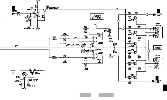
5 |
6 |
7 |
8 |
A
B
C
D
SW for Mute Control
B 1/3
|
(FL) |
|
|
(FL) |
|
|
(FL) |
|
|
Mute |
|
|
SW |
|
|
(FL) |
|
|
(FL) |
|
(FL) |
Mute |
|
SW |
||
|
Mute
SW
Mute
SW
Reference Voltage Gen.
for Audio Amp.
DV-470-S
5 |
6 |
|
|
|
7 |
B 2/3
L |
AUDIO |
|
OUT 2 |
R |
(2 ch) |
|
E |
(FL)
L AUDIO
OUT 1
R (2 ch)
B 2/3 |
F |
B 3/3
27
8
Loading...