


Welcome to digital television
Congratulations on choosing the Philips' DTR 1500 digital terrestrial receiver. The DTR 1500 will allow you to enjoy access to Freeview digital terrestrial television, radio and interactive channels.
English
CONTENTS
1Safety instructions _______________3
2Unpacking / Putting the receiver in your existing set up ______________4
2.1Unpacking ______________________4
2.2Putting the receiver in your existing set up _________________________4
3Product description ______________5
3.1Front view _____________________5
3.2Rear view ______________________6
4Preparing your remote control ____7
4.1Installating the batteries ___________7
4.2Using the remote control _________8
5Connecting your Digital receiver __9
5.1Connecting to a TV fitted with one SCART socket __________________9
5.2Connecting to a TV and a VCR both fitted with one SCART socket _____10
5.3Connecting to your HiFi / Audio receiver equipment
(Analogue / Digital) _____________11
5.4Connection of a Video projector to your receiver to watch Digital TV programmes on a video projector __11
6Quick start up / First installation / Channel scan ___________________12
6.1Quick start ____________________12
6.2Scanning has failed / check installation / check signal from aerial __________12
6.3Scanning has failed again _________13
7Day to day operation ____________14
7.1Switch ON / Switch OFF your receiver (low power, standby) _____14
7.2Select TV / Radio mode __________14
7.3Change channel ________________14
7.4Zap banner / More programme
info _________________________15
7.5Volume control - Vol+ / Vol- /
Mute _________________________16
7.6Select a favourite list ____________16
7.7Temporarily change the Subtitle selection (circular toggle) ________16
7.8Temporarily change the Audio language selection (circular
toggle) ________________________16
7.9Electronic channel guide _________16
7.10Set Timer / Set Reminder from Guide or Zap list / Zap banner - Delete a timer _________________________17
7.11TEXT – MHEG interactive
television _____________________17
CONTENTS 1

7.12Alarm Notification/ Recording – Reminder – New services –
Software download _____________17
English |
7.12.1 |
Recording / Timer |
______________18 |
7.12.2 |
Recording Failure |
_______________18 |
|
7.12.3 |
Reminder ______________________18 |
||
|
7.12.4 |
List of New channels _____________18 |
|
|
7.12.5 |
Software download |
______________18 |
7.13Using the TV / STB button _______18
7.14Watching locked channels ________18
7.15On screen indication of
Radio mode ___________________19
7.16On screen indication of
Loss of signal __________________19
7.17If your receiver is in “Standby” or “Low power” mode and the right-hand,
red LED is blinking… ___________19
7.18How do I reset my receiver if it “freezes”? ____________________19
8Changing the settings on your receiver _______________________20
8.1Menu navigation / item selection / change settings / store changes ____20
8.2Change the installation settings ____21
8.2.1Receiver settings ________________21
8.2.2Channel installation ______________22
8.2.3Check signal quality / check your
aerial _________________________23
8.2.4Software ______________________24
8.2.5Timers (schedule, delete, edit,
conflict…) _____________________24
8.2.6Edit a timer ____________________25
8.2.7Remove a timer via the MENU _____25
8.2.8Disable Recording (Manage conflicts) _25
8.3Favourite list editing _____________26
8.4Parental control / pin Code - lock Programme - Parental timer ______28
8.4.1Change PIN ___________________28
8.4.2Parental control _________________28
8.4.3Maturity level __________________28
8.4.4Lock TV or Radio channel _________28
8.4.5Edit a parental timer _____________29
8.4.6Del. parental timer _______________29
8.5Preferences / language - timer - banner _______________________29
9Menu tree _____________________30
10 Advanced settings ______________31
10.1Restore virgin mode _____________31
10.2Change remote control settings ___31
10.3You forgot your PIN code /
Master PIN code _______________32
10.4More about Recording / Easy Recording – VCR control _________32
11Trouble shooting guide __________34
12Technical specification ___________36
2 CONTENTS

1 Safety instructions
All the safety and operating Instructions should be read and understood before the receiver is operated.
For best results, position your receiver away from radiators or other heat sources. Leave a space of at least 3 cm around the receiver for ventilation making sure that the ventilation holes are not obstructed.
This receiver is intended for use in a domestic environment only and should never be operated or stored in excessively hot, humid or damp conditions.
Make sure no objects or fluids enter the housing through the ventilation slots. Should this happen, disconnect your receiver from the mains and consult your retailer.
For cleaning, use a damp chamois leather. Never use any abrasive cloth, sponge or cleaner.
When connecting or disconnecting cables to the receiver always ensure the receiver is disconnected from the mains.
Please wait before connecting your receiver - read on.
Do not disassemble the equipment. There are no user serviceable parts.
Mains connection
Before connecting the receiver to the mains, check that the mains supply voltage corresponds to the voltage printed on the rear of the receiver. If the mains voltage is different, consult your dealer.
Important:
This apparatus is fitted with an approved moulded BS1363 plug.
To change a fuse in this type of plug proceed as follows:
1.Remove fuse cover and fuse.
2.Fit new 3A fuse that should be a BS1362 ASTA approved type.
3.Refit the fuse cover.
If the fitted plug is not suitable for your socket outlets, it should be cut off and the appropriate plug fitted in its place. If the mains plug contains a fuse, this should have a value of 3A.
If a plug without a fuse is used, the fuse at the distribution board should not be greater than 5A.
Note: The severed plug must be destroyed to avoid a possible shock hazard, should it be inserted into an appropriate socket elsewhere.
How to connect a plug
The wires in the mains lead are coloured in accordance with the following code:
-BLUE - “NEUTRAL” (“N”)
-BROWN - “LIVE” (“L”)
1 The BLUE wire must be connected to the terminal, which is marked with the letter “N” or coloured BLACK.
2The BROWN wire must be connected to the terminal, which is marked with the letter “L” or coloured RED.
3Do not connect either wires to the earth terminal in the plug that is marked by the letter “E” or by the safety earth symbol or coloured green or green-and-yellow. Before replacing the plug cover, make certain that the cord grip is clamped over the sheath of the lead - not simply over the two wires.
Please wait before connecting your receiver - read on.
English
SAFETY INSTRUCTIONS 3
English
2 Unpacking / Putting the receiver in your
existing set up
2.1 Unpacking
Start by unpacking your receiver. You will find the following cables and accessories:
-The digital terrestrial receiver
-The remote control and batteries (2 x LR6 AA 1,5 V)
-One SCART lead
-One RF coaxial lead
-A mains cord
-A user manual
-A Guarantee card
-A stand for using the receiver in the upright position.
Note: As advised in chapter 5 make use of the Scart lead provided. It has been selected to get the best picture quality and performance out of your digital receiver.
Plastic bags can be dangerous. To avoid suffocation keep the bag away from babies and children.
The Symbol  on the packaging means that material is recyclable.
If the receiver will not be used for a long time, unplug the mains cord from the wall socket.
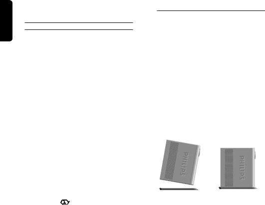
2.2Putting the receiver in your existing set up
-Your receiver can be integrated in different ways within your existing AudioVideo set up. The receiver can be used in the horizontal or vertical position. If you decide to use your receiver in the upright position, follow the instructions below. Unpack the stand, place it on a horizontal surface with click fit side on the left and lug side on the right.
-Take the receiver as shown below (rear panel on the left side / coaxial connectors on the bottom side).
-Insert the stand lug in the slot located on the front of the receiver, close to the Philips badge.
-Rock the receiver to insert the stand lug fully in the slot until it is locked by the click fit.
-From now on, your receiver can be used in the upright position.
Note: Removing the stand can be done by first unlocking the click fit at the rear side of the stand, rocking and pulling back the receiver to extract it from the stand lug.
4 UNPACKING
3 Product description
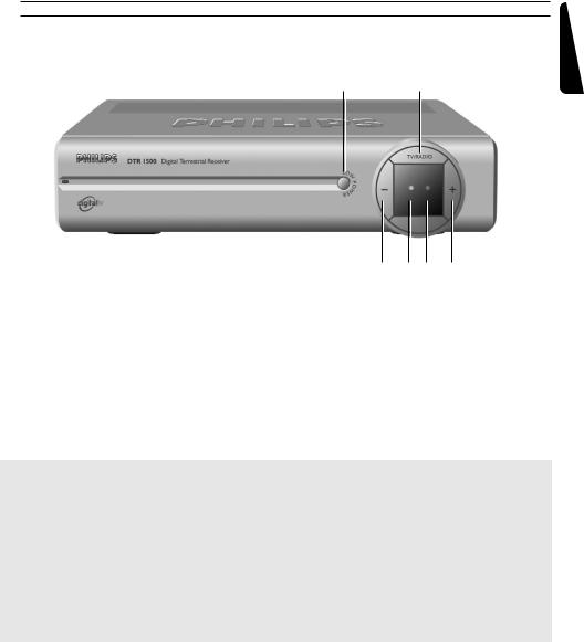
3.1 Front view
1 2
|
|
|
|
|
|
|
|
|
|
3 |
4 |
5 |
6 |
|
1 |
LOW POWER button: |
|
Switch receiver ON or into low power mode |
|||||||||
|
2 |
TV/RADIO button: |
|
Toggle between TV and Radio mode. |
|
|
|||||||
|
3 |
“-” button: |
|
|
Channel down |
|
|
|
|
||||
|
4 |
Three colours LED indicator: |
Display receiver status (see status indicator table) |
||||||||||
|
5 |
Red LED indicator: |
|
Display receiver status (see status indicator table) |
|||||||||
|
|
|
|
|
|
Blink at remote control command reception |
|||||||
|
6 |
“+” button: |
|
|
Channel up |
|
|
|
|
|
|||
|
|
|
|
|
|
|
|
|
|
|
|
|
|
|
|
|
|
|
|
|
Status indicator table |
|
|
|
|||
|
|
|
|
|
|
|
|
|
|
|
|
||
|
|
Mode |
|
Receiver |
Low power |
Standby |
|
TV mode |
Radio |
Software |
Timer |
||
|
LED |
|
|
off mains |
mode |
|
mode |
|
|
mode |
update |
running |
|
|
|
|
|
|
|
|
|
|
|
|
|
|
|
|
4 Left hand LED |
|
Off |
Off |
|
Orange |
|
Green |
Blinking |
Off |
|
Green or |
|
|
(3 colour) |
|
|
|
|
|
|
|
Green - |
|
|
Orange |
|
|
|
|
|
|
|
|
|
|
|
Orange |
|
|
(in standby mode) |
|
|
|
|
|
|
|
|
|
|
|
|
||
|
5 Right hand |
|
Off |
Red |
|
Off |
|
Off |
Off |
Blinking |
Red |
||
|
LED (Red) |
|
|
|
|
|
|
|
|
red |
|
(blinking if |
|
|
|
|
|
|
|
|
|
|
|
|
|
|
|
Note: To cancel a running timer, press button sequence: TIMER + 0.
English
PRODUCT DESCRIPTION 5

English
3.2 Rear view
1 |
2 |
3 |
4 |
||||
|
|
|
|
|
|
|
|
|
|
|
|
|
|
|
|
|
|
|
|
|
|
|
|
|
|
|
|
|
|
|
|
|
|
|
|
|
|
|
|
|
|
|
|
|
|
|
|
|
5 |
6 |
7 |
8 |
9 |
1 |
VCR (SELV): |
|
SCART (1) socket to connect your video recorder |
||
2 |
Digital audio output (SELV): |
|
Coaxial Digital audio output to connect your HIFI / Audio |
||
|
|
|
receiver system |
|
|
3 |
Serial (SELV): |
|
RJ 9 socket for serial data transfer during servicing |
||
4 |
AERIAL IN (SELV): |
|
Input to connect your UHF aerial |
|
|
5 |
230 V ~ 50 Hz 15W max (HV): |
Socket to connect the Mains cord |
|
||
6 |
Label showing the type and serial number of the receiver |
|
|
||
7 |
TV (SELV): |
|
SCART (1) socket to connect to your TV set or a video |
||
|
|
|
projector (2) |
|
|
8 |
L/R Audio out (SELV): |
|
Left/Right audio-cinch outputs to connect your HIFI / Audio |
||
|
|
|
receiver system |
|
|
9 |
RF out (SELV): |
|
RF output to be connected to the aerial input of your Video |
||
|
|
|
Recorder or TV set, refer to chapter |
5 for recommended |
|
|
|
|
connection diagrams. |
|
|
(1)SCART is also called Euroconnector or Peritel.
(2)To connect a video projector to the TV SCART socket refer to chapter 5.4
SELV : Safety Extra Low Voltage.
HV : Hazardous Voltage.
6 PRODUCT DESCRIPTION

4 Preparing your remote control
4.1 Installating the batteries
-Remove the back cover.
-Insert two batteries (type R06G/AA - 1.5 V) supplied.
-Place them in the remote control battery compartment as shown in the diagram.
-Replace the cover.
-Your remote is now ready to control your digital terrestrial receiver.
The Philips batteries supplied with your receiver’s remote do not contain heavy metals such as Mercury or Lead Cadmium. Nevertheless, in many countries exhausted batteries may not be disposed of with your household waste. Please ensure you dispose of empty batteries according to local regulations.
English
PREPARING YOUR REMOTE CONTROL 7

English
4.2 Using the remote control
Mute ?
Audio mute.
RED, GREEN, YELLOW, BLUE: used by interactive television applications.
FAV
-Short key press selects the next favourite list
-Long key press displays all available lists.
SUBTITLE ?
-Temporarily starts or stops Audio Subtitling.
I-II
-Temporary update of audio language.
MENU
-Open menu (in digital TV mode).
-Close menu (in digital TV mode).
Cursor 8/9 The four cursor keys are used to move within the menus and lists.
OK key
-Select / call up programme list / zap.
Volume = +/ -
Volume Up / Down.
TV / STB
Toggle between Digital TV and Analogue transmission from your TV.
Standby *
Standby.
$(blue) resp. % (white)
- Scrolls one Page Up or one Page Down in guide or favourites list.
TEXT / WHITE key Launches Digital Teletext when available.
GUIDE
- Open Now & Next Guide.
INFO
- Open info banner.
- Show extended program information.
- Close banner.
TIMER
- Set a timer (recording or reminder) when in program banner, Guide and Zap List.
The "TIMER, 0" sequence keystroke deletes the current running timer.
BACK (see 7.3.3)
- Selects the previously watched digital TV channel.
- In menu mode
bring selection one level back.
P+ / P-
Selection of Next / Previous channel.
TV / RADIO
Toggle TV / Radio mode.
0-9
Channel selection in digital TV mode.
8 PREPARING YOUR REMOTE CONTROL
5 Connecting your Digital receiver
There are several ways you can connect and incorporate your digital receiver into your existing audio / video equipment set up.
Warning before starting to connect:
-Unplug all equipment (TV set as well as VCR and / or DVD if required) from the mains.
-Do not connect your digital receiver to mains supply now.
-Check your current wiring because you might keep existing connections of your current Audio / Video set up.
-Choose the relevant connecting method for incorporating your digital receiver into your existing Audio / Video set up. Please read chapters 5.1 and 5.2.
English
5.1 Connecting to a TV fitted with one SCART socket
Incorporate your receiver in your existing installation as shown below:
Aerial previously in the back of your TV or Video
SCART lead (supplied)
TV set
EXT1
RF lead (supplied)
-Plug your aerial lead plug into the “AERIAL IN” socket of your digital receiver.
-Connect the “RF OUT” socket of your digital receiver to the “Aerial input” socket of your TV by means of the RF coaxial lead supplied with your digital receiver.
-Connect the “TV” SCART socket of your digital receiver to the “EXT1” SCART socket of your TV set by means of the SCART lead supplied with your digital receiver.
-Plug all your equipment, excluding your digital receiver, into the mains.
-Switch on your TV and select a channel.
CONNECTING YOUR DIGITAL RECEIVER 9

English
-Plug your digital receiver into the mains. Your digital receiver will display the WELCOME screen (the left-hand LED will be illuminated green).
-Go to chapter 6 to proceed with the channel scan of your digital receiver.
If the WELCOME screen is not displayed, press two times the TV/STB button to get the screen displayed.
Note:
With this connection set up you can:
-Watch digital terrestrial TV by means of your Digital receiver.
-Continue watching analogue TV by means of your TV.
5.2 Connecting to a TV and a VCR both fitted with one SCART socket
Incorporate your receiver in your existing installation as shown below:
SCART lead (supplied) |
|
TV set |
|
|
RF lead (supplied) |
EXT1 |
|
EXT1 (out) |
EXT2 (in) |
Video recorder |
|
-Plug your aerial lead plug into the “AERIAL IN” socket of your digital receiver.
-Connect the “RF OUT” socket of your digital receiver to the “Aerial input” socket of your VCR by means of the RF coaxial lead supplied with your digital receiver.
-Connect the “RF OUT” socket of your VCR to the “Aerial input” socket of your TV by means of a RF coaxial lead.
-Connect the “TV” SCART socket of your digital receiver to the “EXT1” SCART socket of your TV by means of the SCART lead supplied with your digital receiver.
-Connect the “VCR” SCART socket of your digital receiver to the “EXT1” SCART socket of your VCR (so called OUT) by means of a SCART lead.
10 CONNECTING YOUR DIGITAL RECEIVER
 Loading...