


DigitalDiagnost
12.18.07
Philips Medical Systems
www.medical.philips.com/us
Note for Architects and/or Contractors: "If revisions are listed, these drawings must be thoroughly reviewed so that all changes can be incorporated into your project"
Rev.
Level
Date Revision Descriptions By
Revisions
Table of Contents
Section A - Equipment Plan
General Notes -------------------------------------- AN
Equipment Plan ------------------------------------- A1
Equipment Details ----------------------- AD1 - AD2
Transport Details --------------------------------- AD3
Section S - Support Plan
Support Notes --------------------------------------- SN
Support Plan - Floor and Wall ------------------- S1
Support Plan - Ceiling------------------------------ S2
Support Details --------------------------- SD1 - SD2
Not Site Specific
Digital Diagnost VM
- Standard Reference Drawing -
Date
Quote Number O.A. Number
Drawn By
Section E - Electrical Plan
Electrical Notes ------------------------------------ EN
Electrical Plan -------------------------------- E1 - E2
Electrical Details --------------------------------- ED1
Section N - Network Plan
Network Diagram ---------------------------------- N1
Check List ----------------------------------------- CHK
N-SRD040005
Project Number
C1
Sheet 1 of 17
THE INFORMATION IN THIS PACKAGE IS PROVIDED AS A CUSTOMER CONVENIENCE, AND IS NOT TO BE CONSTRUED AS ARCHITECTURAL DRAWINGS OR CONSTRUCTION DOCUMENTS.
Philips assumes no liability nor offers any warranty for the fitness or adequacy of the premises or the utilities available at the premises in which the equipment is to be installed, used, or stored.
HVAC Requirement for General Equipment Locations
Heating, ventilation, air conditioning requirement for general equipment locations must
maintain temperature at 75° +/- 11° fahrenheit (24° +/- 6° celsius) and non-condensing
relative humidity at 47%, +/- 28%.
Electrical Requirements
Optimus 65/80/C
Supply Configuration: 3 phase, 3 wire power and ground. Delta or wye
Nominal Line Voltage: 400, 440, 460 or 480 VAC, 60 Hz
Branch Power Requirement: 150 KVA
Circuit Breaker: 3 pole, 100 Amps (@ 480V)
(03.0)
(06.0)
Minimum Site Preparation Requirements
A smooth efficient installation is vital to Philips and its' customers. Understanding what the
minimum site preparation requirements are will help achieve this goal. The following list clearly
defines the requirements which must be fulfilled before the installation can begin.
1. Walls to be painted or covered, baseboards installed, floors to be tiled and/or covered,
ceiling shall have grid tiles and lighting fixtures installed.
2. Doors and windows, especially radiation protection barriers, installed and finished with
locksets operational.
3. All electrical convenience, conduit, raceway and junction boxes installed.
4. Incoming mains power operational and connected to room x-ray breaker.
5. 115v convenience outlets operational.
6. All support structures correctly installed. All channels, pipes, beams and/or other supporting
devices should be level, parallel, and free of lateral or longitudinal movements.
7. All contractor supplied cables pulled and terminated.
8. A dust-free environment in and around the procedure room.
9. All HVAC (heating, ventilating and air conditioning) installed and operational as per
specifications.
10. Architectural features such as computer floor, wood floor, casework, bulkheads, installed
and finished. When technical cabinets are installed in a closet with doors, it is suggested that
the customer install a temperature alarm in the event of an air conditioning failure.
11. All plumbing installed and finished.
12. Philips does not install or connect developing tanks, automatic processors or associated
equipment, built in illuminators, cassette pass boxes, loading benches and cabinets, lead
protective screens, panels or lead glass window and frame. This is to be done by the
customer/contractor.
13. Clear door openings for moving equipment into the building must be 42" (1067mm) w x 82"
(2083mm) h min. 48" (1219mm) w x 82" (2083mm) h rec., or larger contingent on an 8'-0"
(2438mm) corridor width.
Note
Once Philips has moved equipment into the suite and started the installation, the contractor
shall schedule his work around the Philips installation team on site. It is suggested that a
telephone be provided in the room to receive telephone calls. This would alleviate facility staff
from answering calls for Philips personnel.
Remote Service Diagnostics
Medical imaging equipment to be installed by Philips Medical is equipped with a service
diagnostic feature which allows for remote and on site service diagnostics. To establish this
feature, a dedicated direct-distance - dialing, voice-grade line must be installed as shown on
plan. All costs with this feature are the responsibility of the customer.
(00.1)
General Specifications
1. Responsibility
The customer shall be solely responsible, at its expense for preparation of site, including any
required structural alterations. The site preparation shall be in accordance with plans and
specifications provided by Philips. Compliance with all safety, electrical, and building codes
relevant to the equipment and its installation is the customer's responsibility. Sufficiency of
such plans and specifications, specifically including, but not limited to the accuracy of the
dimensions described therein, shall be the sole responsibility of customer. The customer shall
advise Philips of conditions at or near the site which could adversely affect the carrying out of
the installation work and shall ensure that such conditions are corrected and that the site is fully
prepared and available to Philips before the installation work is due to begin. The customer
shall provide all necessary plumbing, carpentry work, or conduit wiring required to attach and
install products ready for use.
2. Permits
Customer shall obtain all permits and licenses required by federal, state/provincial or local
authorities in connection with the construction, installation and operation of the products and
shall bear any expense in obtaining same or in complying with any related rules, regulations,
ordinances and statutes.
3. Radiation Protection
The customer or his contractor, at his own expense, shall obtain the service of a licensed
radiation physicist to specify radiation protection. For the purpose of the radiation protection
design for the suite, the physicist should assume a maximum kVp x-ray tube output of 150.
4. Asbestos and Other Toxic Substances
Philips assumes no hazardous waste (i.e., pcb's in existing transformers) exists at the site. If
any hazardous materials are found, it shall be the sole responsibility of the customer to properly
remove and dispose of this material at its expense. Any delays caused in the project for this
special handling shall result in Philips time period for completion being extended by like period
of time. Philips assumes that no asbestos material is involved in this project in any ceilings,
walls or floors. If any asbestos material is found anywhere on the site, it shall be the
customer's sole responsibility to properly remove and/or make safe this condition, at the
customer's sole expense.
5. Labor
In the event local labor conditions make it impossible or undesirable to use Philips' regular
employees for such installation and connection, such work shall be performed by laborers
supplied by the customer, or by an independent contractor chosen by the customer at the
customer's expense, and in such case, Philips agrees to furnish adequate engineering
supervision for proper completion of the installation.
6. Schedule
The general contractor should provide Philips with a schedule of work to assist in the
coordination of delivery of Philips supplied products which are to be installed by the contractor
and delivery of the primary equipment.
7. Extended Installation or Turnkey Work by Philips.
Any room preparation requirements for Philips equipment indicated on these drawings is the
responsibility of the customer. If an extended installation or turnkey contract exists between
Philips and the customer for room preparation, then additional work required for the equipment
will not be represented on these drawings. Some of the responsibilities of the customer as
depicted in these drawings may be assumed by Philips. In the event of a conflict between the
work described in the turnkey contract workscope and these drawings, the turnkey contract
workscope shall govern.
(00.0)
12.18.07
Not Site Specific
Digital Diagnost VM
- Standard Reference Drawing -
Date
Quote Number O.A. Number
Drawn By
N-SRD040005
Project Number
AN
Sheet 2 of 17
THE INFORMATION IN THIS PACKAGE IS PROVIDED AS A CUSTOMER CONVENIENCE, AND IS NOT TO BE CONSTRUED AS ARCHITECTURAL DRAWINGS OR CONSTRUCTION DOCUMENTS.
Philips assumes no liability nor offers any warranty for the fitness or adequacy of the premises or the utilities available at the premises in which the equipment is to be installed, used, or stored.
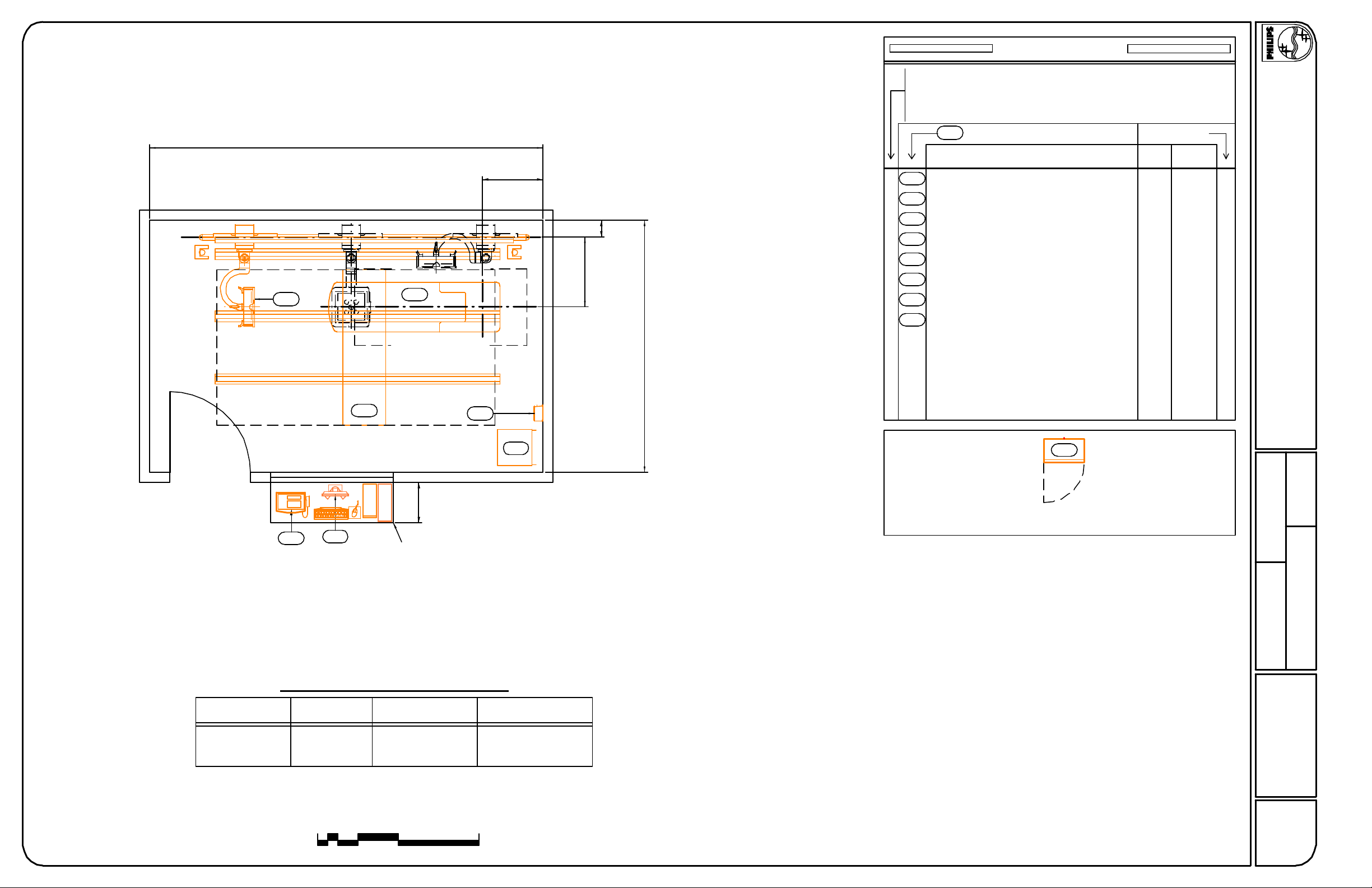
19'-6"
Table Floorplate Centerline
3'-0"
Equipment Legend
A
Furnished and installed by Philips
B
Furnished by customer/contractor and installed by customer/contractor
C
Installed by customer/contractor
Furnished by Philips and installed by contractor
D
E
Existing
F
Future
G
Option
Equipment Designation
Description
A
Detail Sheet
Weight
Heat Load
(btu/hr)(lbs)
1707462Optimus 80 Control Cabinet (40E Rack)ME
12.18.07
AD1
4' Wide Patient Entry
(Recommended)
DVM
PBC
DDW
MU
MS
2'-0"
Counter provided and
installed by customer
SCU
ME
10"
Floor Rail
Centerline
3'-5 1/2"
Table Longitudinal Centerline
12'-6"
A
A
A
A
A
A
A
MSC
Final location to be coordinated with the customer and architect of record.
AD1
1379Optimus Control PanelPBC
AD1
1297810CS 2 Tube Crane w/ Cable Carrier RailMU
AD1
060Manual Storage CabinetMSC
AD1
11914Segment Control UnitSCU
AD2
444753Digital Diagnost VM (Left)DVM
AD2
2083176Digital Diagnost WorkstationDDW
AD2
341472Single Sided Table TH-SMS
Not Site Specific
Digital Diagnost VM
- Standard Reference Drawing -
Date
Equipment Layout
Wall Stand Tube Position
Digital
Diagnost VM
Reported Existing Ceiling Height : None
Ceiling heights (from finished floor to bottom of Unistrut) other than
recommended may impact equipment functionality; consult with Philips.
0 8'1'
Minimum/Preferred
Ceiling Height
2'
4'
9' - 10 1/8" (3000mm)8' - 8 3/8" (2650mm)Upper Position
11' - 1 3/4" (3400mm)9' - 11 3/4" (3040mm)Lower Position
Maximum
Ceiling Height
Quote Number O.A. Number
Drawn By
N-SRD040005
Project Number
A1
Sheet 3 of 17
THE INFORMATION IN THIS PACKAGE IS PROVIDED AS A CUSTOMER CONVENIENCE, AND IS NOT TO BE CONSTRUED AS ARCHITECTURAL DRAWINGS OR CONSTRUCTION DOCUMENTS.
Philips assumes no liability nor offers any warranty for the fitness or adequacy of the premises or the utilities available at the premises in which the equipment is to be installed, used, or stored.

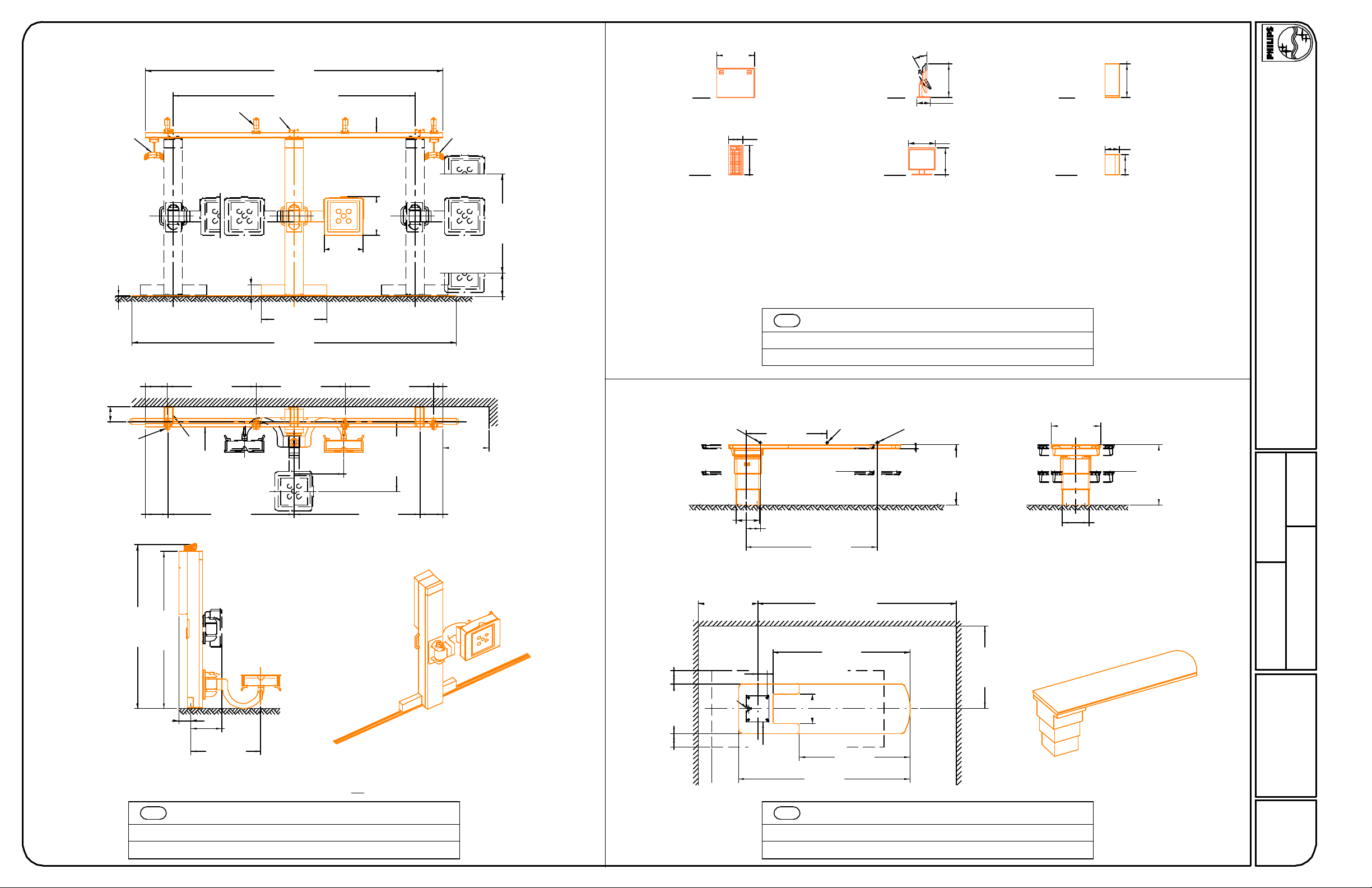
Optional Wall Mounting Bracket
12.18.07
max.
107.47"
2730mm
25.59"
650mm
8.27"
210mm
min.
49.22"
1250mm
90°
90°
Option:
Tomo
Option:
Tomo
92.13"
9.57"
243mm
max.
2340mm
33.86"
min.
860mm
14.96"
380mm
92.76"
2356mm
34.41"
874mm
Option:
Tomo
57.87"
1470mm
9.49"
241mm
*
Option:
Tomo
25.59"
36.00"
914mm
9.49"
241mm
650mm
Option:
Rail for
Cable Carrier
4.49"
114mm
3.07"
78mm
6.00"
152mm
PBC
Weight
Heat Dissipation
15.75"
400mm
16.93"
430mm
Optimus Control Panel
9 lbs (4 kg)
137 Btu/hr (35 kcal/hr)
11.03"
13.19"
335mm
280mm
.79"
20mm
(07.0)
24.02"
610mm
30.00"
762mm
Max. weight of cabinet with manuals = 260 lbs. (118 kg)
MSC
Weight
Heat Dissipation
Manual Storage Cabinet
14.02"
356mm
60 lbs (27 kg)
0 Btu/hr ( 0 kcal/hr)
2.56"
65mm
(03.0)
Not Site Specific
Digital Diagnost VM
- Standard Reference Drawing -
8x45º
11.81"
300mm
Option:
Tomo
Supporting Arm UpSupporting Arm Down
* Column movement range = 1260mm (49.61");
standard range of 1470mm reduced by 210mm
(8.28") to allow optional cable carrier to be
mounted on transverse carriage.
* Optional cable carrier can be mounted on
longitudinal rail, causing 210mm (8.28") of
tube crane coverage loss (foot or head-end).
MU
Weight
Heat Dissipation
* Extension Rails are an additional 113lbs (51kg).
CS 2 Tube Crane
8x45º
Longitudinal
Rail
(368 kg)810 lbs
(326 kcal/hr)1297 Btu/hr
Transverse
Carriage
Option:
Cable Carrier
(07.1)
5.47"
139mm
8.94"
227mm
Cable
Openings
SCU
Weight
Heat Dissipation
21.06"
535mm
1.97"
50mm
42.50"
1080mm
±
Segment Control Unit
14 lbs (6 kg)
119 Btu/hr (30 kcal/hr)
(07.0)
2.76"
70mm
Clear Area
Around Cabinet
ME
Weight
Heat Dissipation
20.48"
520mm
21.66"
550mm
Optimus 50/65/80 Control Cabinet
2.76"
70mm
7.88"
200mm
76.98"
1955mm
462 lbs (210 kg)
1707 Btu/hr (430 kcal/hr)
Filler Panel
(07.0)
Date
Quote Number O.A. Number
Drawn By
N-SRD040005
Project Number
AD1
Sheet 4 of 17
THE INFORMATION IN THIS PACKAGE IS PROVIDED AS A CUSTOMER CONVENIENCE, AND IS NOT TO BE CONSTRUED AS ARCHITECTURAL DRAWINGS OR CONSTRUCTION DOCUMENTS.
Philips assumes no liability nor offers any warranty for the fitness or adequacy of the premises or the utilities available at the premises in which the equipment is to be installed, used, or stored.
22.44"
177.17"
4500mm
143.70"
A
3650mm
B
max.
guide rail
570mm
Side
Side
30°
max
19.92"
506mm
8.07"
205mm
Top
20.32"
516mm
12.18.07
cable carrier
for CS 2/4
.63"
13.27"
337mm
min.
max.
9.06"
230mm
13.38"
340mm
13.78"
350mm
16mm
A
52.83"
1342mm
B
guide rail
74.80"
1900mm
User side left User side right (default)
22.64"
575mm
23.46"
596mm
6.89"
175mm
39.37"
1000mm
192.91"
4900mm
52.83"
1342mm
52.83"
1342mm
29.53"
750mm
74.80"
1900mm
41.54"
1055mm
cable carrier
for wall stand
min.
5.39"
137mm
27.56"
700mm
13.78"
350mm
59.06"
1500mm
13.78"
350mm
Required for insertion
of column
8.07"
205mm
Front
17.52"
445mm
CPU (Sun Ultra 25)
Weight: 60 lbs (27 kg)
Heat Dissipation: 1707 btu/hr (430 kCal/hr)
DDW
Weight
Heat Dissipation
center of gravity
table
13.80"
350mm
48.31"
1227mm
8.66"
220mm
center of gravity
table & patient
78.27"
1988mm
15.91"
404mm
Front
15.98"
406mm
19 " LCD Color Monitor
Weight: 16 lbs (8 kg)
Heat Dissipation: 171 btu/hr (43 kCal/hr)
Digital Diagnost Workstation
center of gravity
patient
2.13"
54mm
max.
min.
20.08"
510mm
35.83"
910mm
8.31"
211mm
Front
12.01"
305mm
UPS
Weight: 100 lbs (46 kg)
Heat Dissipation: 205 btu/hr (93 kCal/hr)
(07.0)
(81 kg)176 lbs
(566 kCal/hr)2083 Btu/hr
29.53"
750mm
35.83"
910mm
max.
20.08"
510mm
15.87"
403mm
min.
Not Site Specific
Digital Diagnost VM
- Standard Reference Drawing -
Date
97.64"
2480mm
93.70"
2380mm
7.22"
183mm
Guide rail to be supported using ceiling holders (A) OR wall holders (B)
DVM
Weight
Heat Dissipation
18.10"
460mm
41.54"
1055mm
Digital Diagnost VM
(342 kg)753 lbs
(112 kcal/hr)444 Btu/hr
(06.0)
wall clearance required for
installation and service of table base
7.87"
200mm
29.53"
750mm
7.87"
200mm
min.
cable
outlet
15.75"
400mm
35.43"
900mm
5.55"
141mm
floor plate
Weight
Heat Dissipation
wall clearance required for insertion of tabletop
118.11"
min.
3000mm
81.89"
2080mm
17.72"
450mm
66.14"
1680mm
102.36"
2600mm
MS
Single Sided Table TH-S
472 lbs (214 kg)
341 Btu/hr (86 kcal/hr)
49.21"
1250mm
wall clearance required for
installation and service of table base
(06.0
Quote Number O.A. Number
Drawn By
N-SRD040005
Project Number
AD2
Sheet 5 of 17
THE INFORMATION IN THIS PACKAGE IS PROVIDED AS A CUSTOMER CONVENIENCE, AND IS NOT TO BE CONSTRUED AS ARCHITECTURAL DRAWINGS OR CONSTRUCTION DOCUMENTS.
Philips assumes no liability nor offers any warranty for the fitness or adequacy of the premises or the utilities available at the premises in which the equipment is to be installed, used, or stored.
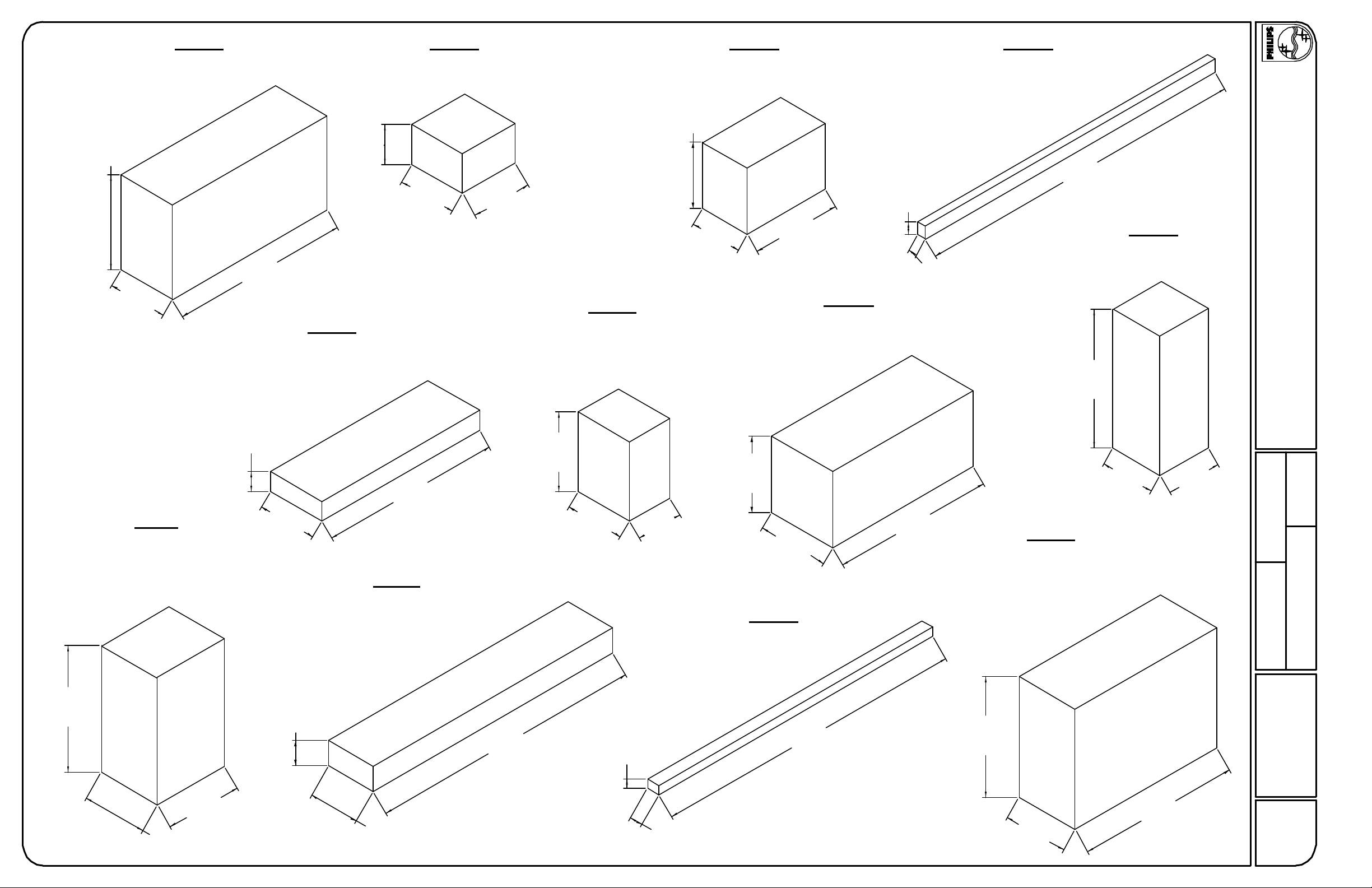
4'-8.30"
1430mm
2'-11.43"
900mm
Crate A
Moveable Column
Weight: 629 lbs.
8'-10.30"
2700mm
1'-11.62"
600mm
Crate E
Single Sided Table TH-S
Table Top
Weight: 270 lbs.
Crate B
Flat Detector
Weight: 99 lbs.
2'-10.65"
880mm
3'-.22"
920mm
Digital Bucky Unit with Swivelling Arm
Crate F
Single Sided Table TH-S
Table Base
Weight: 450 lbs.
Crate C
Weight: 281 lbs.
3'-3.37"
1000mm
2'-6.71"
780mm
7.87"
200mm
4'-5.54"
1360mm
5.12"
130mm
Crate G
Single Sided Trolley TF-M
Weight: 584 lbs.
Crate D
Floor Rail and Guide Rail
Weight: 135 lbs.
16'-6.82"
5050mm
Generator Cabinet
6'-10.68"
12.18.07
Crate H
Weight: 508 lbs.
Not Site Specific
Digital Diagnost VM
- Standard Reference Drawing -
2100mm
Crate I
CS4 Transverse Carriage
Weight: 562 lbs.
Tomography (option)
Additional Weight: 67 lbs.
6'-3.59"
1920mm
11.81"
300mm
2'-11.43"
900mm
9'-.27"
2750mm
Crate J
CS4 Longitudinal Carriage
Weight: 429 lbs.
1'-2.97"
380mm
13'-8.56"
4180mm
3'-11.24"
1200mm
2'-11.43"
900mm
5.50"
140mm
2'-3.56"
700mm
3'-9.28"
1150mm
3'-6.13"
1070mm
Crate K
CS Base Rails 4.3 m
Weight: 198 lbs.
15'-8.19"
4780mm
8'-.46"
2450mm
2'-8.28"
820mm
Crate L
CS2 Complete
Weight: 931 lbs.
Tomography (option)
Additional Weight: 67 lbs.
5'-11.65"
1820mm
2'-9.07"
840mm
Date
Quote Number O.A. Number
Drawn By
N-SRD040005
Project Number
3'-2.58"
980mm
3'-10.06"
1170mm
2'-6.72"
780mm
7.88"
200mm
3'-2.59"
980mm
8'-1.25"
2470mm
(06.0)
AD3
Sheet 6 of 17
THE INFORMATION IN THIS PACKAGE IS PROVIDED AS A CUSTOMER CONVENIENCE, AND IS NOT TO BE CONSTRUED AS ARCHITECTURAL DRAWINGS OR CONSTRUCTION DOCUMENTS.
Philips assumes no liability nor offers any warranty for the fitness or adequacy of the premises or the utilities available at the premises in which the equipment is to be installed, used, or stored.
 Loading...