


NOTICE DTR 320_290405.qxd 29/04/05 14:07 Page 1

NOTICE DTR 320_290405.qxd 29/04/05 14:07 Page 2
English
Welcome to digital television
Congratulations on choosing the PHILIPS DTR 320 digital terrestrial receiver, which will allow you to access Freeview digital terrestrial television, radio and interactive channels.
With this product, you can enjoy advanced functions and features including:
-Award-winning noise-free reception
-Automatic programme installation
-Wide screen format
-TV SCART and VCR/DVD SCART connectors
-Personal channel list and favourite lists
-Electronic Programme Guide
PHILIPS have made every effort to ensure this product meets your every day needs for years to come.
This User Manual covers the installation of your receiver, together with explanations of the standard and unique features of the product.
Lucas Covers
Paris, March 2005
Meaning of symbols
Important information:
Must be read and understood.
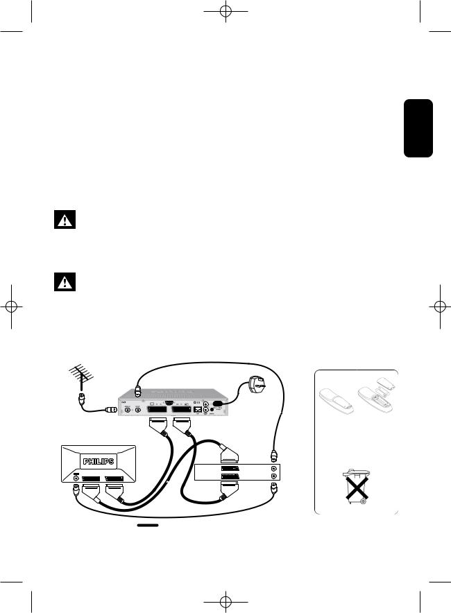
The “crossed-out wheeled bin” means separate disposal is required for the receiver, accessories and used batteries.They mustn’t be disposed of with your household waste.
Please, inquire about the local regulations.
For information: the PHILIPS batteries supplied with your receiver remote do not contain hazardous substances such as Mercury, Cadmium, or Lead.
The “Material recyclability symbol” printed on the cardboard packaging and user manual means these parts are recyclable.
The “Material recyclability symbol” affixed to the plastic packaging parts means these parts are recyclable.
The “Green Dot” affixed on cardboard means PHILIPS pays a financial duty to the “Avoidance and Recovery of Packaging Waste” organization.
2 WELCOME TO DIGITAL TELEVISION
NOTICE DTR 320_290405.qxd 29/04/05 14:07 Page 3
Unpacking
Unpack your receiver and check that the following cables and accessories are also included in the package:
- 1 remote control
- 2 batteries (2 x LR6 AA 1.5 V)
-1 SCART lead
-1 RF coaxial lead
-1 mains cord
-1 user manual
-1 Worldwide Warranty booklet
Plastic bags can be dangerous.To avoid suffocation keep the bags away from babies and children.
Quick installation
Please read the safety section before connecting your receiver.
Requirements for a fast and successful first installation are as follows:
•You already have an aerial.
•Your aerial is correctly pointed at the terrestrial transmitter corresponding to your area.
•Your TV set is switched on.
•Your digital receiver connection is according to the diagram below.
English
T
|
|
|
to AC outlet |
|
|
|
6 |
|
|
RF Cable |
|
|
|
|
TV set |
|
|
|
|
|
|
|
VCR/DVD |
|
E 2 |
EXT 1 |
EXT 1 |
ANT IN |
|
EXT 2 |
ANT OUT |
|||
|
|
For optimum configuration
Batteries can easily be removed using common household tools (screwdriver, etc.).
QUICK INSTALLATION 3

NOTICE DTR 320_290405.qxd 29/04/05 14:07 Page 4
TABLE OF CONTENTS
English |
Welcome to digital television |
|
|
2 |
||||||||||
|
Meaning of symbols |
|
|
|
|
2 |
||||||||
|
|
|
|
|||||||||||
|
Unpacking |
|
|
|
|
3 |
||||||||
|
Quick installation |
|
|
|
|
|
|
|
|
|
3 |
|||
|
Table of contents |
|
|
|
|
|
4 |
|||||||
|
Important safety instructions |
|
|
|
5 |
|||||||||
|
|
|
|
|
|
|
|
|
|
|
|
|
|
|
|
1 |
Product description |
7 |
|||||||||||
|
1.1 |
Front view |
|
|
|
|
|
|
7 |
|||||
|
1.2 |
Rear view |
|
|
|
|
|
|
|
8 |
||||
|
1.3 |
Using the remote control |
|
|
9 |
|||||||||
2 Connecting your digital receiver 10
2.1Connecting to a TV and a VCR both
fitted with one SCART socket |
10 |
2.2Connecting to your HiFi/Audio
|
receiver equipment |
|
|
|||
|
(Analogue/Digital) |
|
|
12 |
||
|
|
|
|
|
|
|
3 |
First installation |
13 |
||||
3.1 |
Channel scan |
|
|
|
13 |
|
3.2 |
Scanning failure |
|
|
|
13 |
|
3.3 |
Repeated scanning failure |
|
13 |
|||
|
|
|
|
|
|
|
4 |
Day to day operation |
14 |
||||
4.1Switching your receiver ON/OFF
|
(standby) |
14 |
4.2 |
Selecting TV/Radio mode |
14 |
4.3Changing channels when watching
|
digital TV or listening to digital radio |
14 |
|||
4.4 |
Channel banner |
|
|
|
15 |
4.5 |
Volume control |
- / |
+ / |
|
15 |
|
|||||
4.6 |
Changing the Subtitle selection |
15 |
4.7Changing the Audio language selection 15
4.8 |
Electronic Programme Guide |
16 |
4.9 |
Timers |
16 |
4.10DIGITAL TEXT - MHEG
|
interactive television |
|
|
16 |
|||||||||
4.11 |
Using the TV / STB button |
|
|
16 |
|||||||||
4.12 |
Watching locked channels |
|
|
|
16 |
||||||||
|
|
|
|
|
|
|
|
|
|
|
|
|
|
5 |
Changing the settings |
|
|
||||||||||
|
of your receiver |
16 |
|||||||||||
5.1 |
General information |
|
|
|
|
|
16 |
||||||
5.2 |
Preferences |
|
|
|
|
|
|
16 |
|||||
5.3 |
Installation |
|
|
|
|
|
|
|
|
20 |
|||
5.4 |
Information |
|
|
|
|
|
|
22 |
|||||
|
|
|
|
|
|
||||||||
5.5 |
Timers |
|
|
|
|
|
|
|
|
23 |
|||
5.6 |
Favourites |
|
|
|
|
|
|
|
|
|
24 |
||
|
|
|
|
|
|
|
|
||||||
5.7 |
Access Restrictions |
|
|
|
|
|
25 |
||||||
|
|
|
|
|
|
|
|
|
|
|
|
|
|
6 |
Menu tree |
26 |
|||||||||||
|
|
|
|
|
|
|
|
|
|
|
|
|
|
7 |
Advanced settings |
27 |
|||||||||||
7.1Changing the remote control setting 27
7.2 |
More about recording |
27 |
8 |
Troubleshooting guide |
29 |
9 |
Technical specifications |
31 |
4 TABLE OF CONTENTS

NOTICE DTR 320_290405.qxd 29/04/05 14:07 Page 5
Important safety instructions
For safe operation and optimal lifetime
Your receiver has been manufactured to meet the appropriate safety standards, but the instructions below must be followed to operate it safely.These instructions must be kept for future reference.
- Before connecting the receiver to the mains, check that the mains supply voltage corresponds to the voltage printed on the rear of the receiver. If the mains voltage is different, consult your dealer.
-The receiver does not contain any user-serviceable parts.All maintenance work must be carried out by qualified personnel.
-If you disconnect the receiver from the mains, make sure you unplug it from the wall socket and not just from the AC socket at the back of the unit. Children could seriously injure themselves, as the free end of the cable is still alive.
-Unplug the receiver during lightning storms.
- To prevent fire or shock hazard, do not expose this equipment to rain or moisture.
-The receiver should be placed on a firm surface, and the ventilation openings must not be covered with items, such as newspapers, table cloths, curtains, etc.
-Do not install the receiver near any heat sources such as radiators, stoves or other apparatus that produce heat. Protect it from direct sunlight.
-When installing the receiver, ensure there is a gap of approximately 2.5 cm around the receiver to enable air to circulate freely and prevent overheating.
-Ensure accessibility is maintained to the mains connector at the back of the unit in case emergency shutdown is required.
- Do not place any combustible objects on the receiver (candles, etc.).
-No objects filled with liquids, such as vases, shall be placed on the unit.The receiver shall not be exposed to dripping or splashing. Should this happen, disconnect your receiver from the mains and consult your dealer.
-Make sure that children do not place any foreign objects in any of the openings.
-For cleaning, use a soft, damp (not wet) cloth. Never use any abrasive cloth or aerosol cleaners.
English
IMPORTANT SAFETY INSTRUCTIONS 5
NOTICE DTR 320_290405.qxd 29/04/05 14:07 Page 6
English
Mains connection
Important note
This apparatus is fitted with an approved moulded BS1363 plug.
To change a fuse in this type of plug proceed as follows:
- |
Remove fuse cover and fuse. |
- |
Fit a new fuse that should be a BS1362 ASTA approved type. |
- |
Refit the fuse cover. |
If the fitted plug is not suitable for your socket outlets, it should be cut off and an appropriate plug fitted in its place. If the mains plug contains a fuse, this should have a value of 3A.
If a plug without a fuse is used, the fuse at the distribution board should not be greater than 5A.
Note: the severed plug must be destroyed to avoid a possible shock hazard, should it be inserted into an appropriate socket elsewhere.
How to connect a plug
The wires in the mains lead are coloured in accordance with the following code:
•BLUE - “NEUTRAL” (“N”)
•BROWN - “LIVE” (“L”)
-The BLUE wire must be connected to the terminal, which is marked with the letter “N” or coloured BLACK.
-The BROWN wire must be connected to the terminal, which is marked with the letter “L” or coloured RED.
-Do not connect either wires to the earth terminal in the plug that is marked by the letter “E” or by the safety earth symbol or coloured green or green-and-yellow. Before replacing the plug cover, make certain that the cord grip is clamped over the sheath of the lead - not simply over the two wires.
6 IMPORTANT SAFETY INSTRUCTIONS

NOTICE DTR 320_290405.qxd 29/04/05 14:07 Page 7
1 Product description
1.1Front view
English
Q W E R
1STANDBY button: . . . . . . . . . . . . . . . . . . . . . . . . Switch the receiver ON or to standby.
2LED1 (Red): . . . . . . . . . . . . . . . . . . . . . . . . . . . . . . . . . Display receiver status (see status indicator table).
3LED2 (Red/Green/Orange): . . . . . . . . . . . . . . Display receiver status (see status indicator table).
4Remote control receiver window
Status indicator table |
|
|
|
|
LED |
|
LED1 |
|
LED2 |
|
|
|||
Mode |
|
(Red) |
|
(Red/Green/Orange) |
|
|
|
|
|
Receiver in Standby |
|
OFF |
|
red |
|
|
|
|
|
Watching TV |
|
OFF |
|
green |
|
|
|
|
|
Listening to the radio |
|
OFF |
|
green, blinking |
|
|
|
|
orange every 20 s |
|
|
|
|
|
Pressing a remote control button |
|
OFF |
|
blinking, colour depending |
|
|
|
|
on current mode |
|
|
|
|
|
Timer active |
|
ON |
|
green |
|
|
|
|
|
Timer active in Standby |
|
ON |
|
red |
|
|
|
|
|
Software download |
|
blinking |
|
Depending on current mode |
|
|
|
|
|
Note: if the red LED is blinking while your receiver is in “Standby”, it indicates that an upgrade of your receiver software is taking place. Do not interrupt this operation.
PRODUCT DESCRIPTION 7

NOTICE DTR 320_290405.qxd 29/04/05 14:07 Page 8
1.2Rear view
English
|
|
|
|
|
|
|
|
|
|
|
|
|
|
|
|
|
|
|
|
|
|
|
|
|
|
|
|
|
|
|
|
|
|
|
|
|
|
|
|
|
|
|
|
|
|
|
|
|
|
|
|
Q |
W |
E |
R |
T |
|
|
I O |
||||||||
|
Y U |
|||||||||||||||
1 |
AERIAL IN (*): . . . . . . . . . . . . . . . . . . . |
. . |
. . . . . |
Input to connect your UHF aerial. |
|
|
|
|||||||||
2 |
RF OUT (*): . . . . . . . . . . . . . . . . . . . . . . . . |
. |
. . . . . |
RF output to be connected to the aerial input of your |
||||||||||||
|
|
|
|
|
|
|
video recorder or TV set, refer to chapter 2 for |
|||||||||
|
|
|
|
|
|
|
recommended connection diagrams. |
|
|
|
||||||
3 |
TV(*): . . . . . . . |
. . |
. . . . . . . . . . . . . . . . . . . . . . . |
. |
. . . . . |
SCART (1) socket to connect your TV set or a video |
||||||||||
|
|
|
|
|
|
|
projector. |
|
|
|
|
|
|
|
|
|
4 |
SERIAL (*): . |
. |
. . . . . . . . . . . . . . . . . . . . . . . |
. |
. . . . . |
RS232 socket for serial data transfer during servicing. |
||||||||||
5 |
VCR (*): . . . . |
. |
. . . . . . . . . . . . . . . . . . . . . . . |
. |
. . . . . |
SCART (1) socket to connect your video recorder. |
||||||||||
6 |
LAN: . . . . . . . . |
. |
. . . . . . . . . . . . . . . . . . . . . . . |
. |
. . . . . |
Currently idle. For future use. |
|
|
|
|||||||
7 |
L/R AUDIO OUT (*): . . . . . . . . . . . . . |
. |
. . . . . |
Left/Right analogue audio-cinch outputs to connect your |
||||||||||||
|
|
|
|
|
|
|
HiFi/audio receiver system. |
|
|
|
|
|
|
|||
8 |
DIGITAL (*): . . . . . . . . . . . . . . . . . . . . . . . |
. |
. . . . . |
Digital audio-cinch output to connect your HiFi/audio |
||||||||||||
|
|
|
|
|
|
|
receiver system. |
|
|
|
|
|
|
|||
9 |
230V~50Hz |
6W max (**): . . . . . . |
. |
. . . . . |
Socket to connect the mains cord. |
|
|
|
||||||||
The label showing the type and serial number is underneath the receiver.
(1) SCART is also called Euroconnector or Peritel.
*Safety Extra Low Voltage
**Hazardous Voltage
8 PRODUCT DESCRIPTION

NOTICE DTR 320_290405.qxd 29/04/05 14:07 Page 9
1.3Using the remote control
0-9 number keys
-In viewing mode: selects channels
-In menu: directly selects a menu item or sets a setting
-In standby: wakes up the receiver
INFO
-Opens the info banner
-Then shows extended program information
-Then closes the banner
EXIT
Currently inactive. For future use.
VOLUME  +/-
+/-
Increases/Decreases the volume level
MUTE 
Audio mute
RED, GREEN,
YELLOW, BLUE
Action depending on context Blue button used to exit most sub-menus
TV/STB
Toggles between digital TV from your receiver and standard analogue TV from your TV set
1-11
Displays available audio languages
MENU
Opens/Closes the Menu
REC
Opens Timer list/Creates timers
Note: the sequence “TIMER, 0” deletes the current active timer
Standby 
Switches your receiver into the standby mode.
EPG
Opens/Closes the Electronic
Programme Guide
BACK
-In viewing mode: returns to the previously tuned channel
-In menu mode: returns to the previous screen.
CURSOR t/y
-Previous/Next channel
-Scrolls up/down in menu/lists
CURSOR i
-Scrolls right
-Opens one menu level down in menu mode
CURSOR u
-Scrolls left
-Opens the previous menu level, or store values
OK
-Displays channel list
-Selects service from channel list or EPG
-Confirms and activates a menu selection
P+ / P-
-Next/Previous channel in digital TV/Radio mode
-Page up/down in service lists
TEXT
Launches digital text when available
SUBTITLE 
Displays available subtitle languages
FAV
Displays available favourite lists
RADIO
Toggles between TV and Radio mode
English
PRODUCT DESCRIPTION 9

NOTICE DTR 320_290405.qxd 29/04/05 14:07 Page 10
English
2 Connecting your digital receiver
There are several ways you can connect and incorporate your digital receiver into your existing audio/video equipment set up.
Warning!
Before starting to connect:
- Unplug all equipment (TV set,VCR and/or DVD, etc.) from the mains.
-Do not connect your digital receiver to the mains supply now.
-Check your current wiring: you may not need to modify your existing Audio / Video set up connections if they already match the connection diagrams below.
-Depending on your exiting set up, choose the best suited connection method for incorporating your digital receiver into your existing Audio / Video set up. Please read chapters 2.1 and 2.2.
Note: when adding new equipment, be sure to refer to the related installation instructions of the relevant manual.
2.1Connecting to a TV and a VCR both fitted with one SCART socket
Incorporate your receiver in your existing installation as shown on the diagrams or follow the instructions below.
10 CONNECTING YOUR DIGITAL RECEIVER
 Loading...