


Philips Consumer Electronics |
Manual 7629 |
Technical Service Data |
Model no.: 27PS55S321 |
First Publish: 12740 T8 |
|
Service and Quality |
Rev. Date: 2002-06-06 |
Print Date: 25/02/2012 |
|
Service Publications Dept. |
|
One Philips Drive |
|
P.O. Box 14810 |
|
Knoxville, TN 37914 |
|
Electrical Adjustments
REFER TO SAFETY GUIDELINES
SAFETY NOTICE: ANY PERSON ATTEMPTING TO SERVICE THIS CHASSIS MUST FAMILIARIZE HIMSELF WITH THE CHASSIS AND BE AWARE OF THE NECESSARY SAFETY PRECAUTIONS TO BE USED WHEN SERVICING ELECTRONIC EQUIPMENT CONTAINING HIGH VOLTAGES.


 CAUTION: USE A SEPARATE ISOLATION TRANSFORMER FOR THIS UNIT WHEN SERVICING
© Philips Electronics North America Corporation |
Visit our World Wide Web Site at http://www.forceonline.com |
Alignments
Index of this chapter:
1.General Alignment Conditions
2.Commercial Models SDAM Entry
3.Hardware Alignments
4.Software Alignments and Settings
Note: The Service Default Alignment Mode (SDAM) is described in the "Service Modes,
Error Codes and Fault Finding" section. SDAM menu navigation is performed by using the MENU UP, MENU DOWN, MENU LEFT, and MENU RIGHT keys of the remote control transmitter.
General Alignment Conditions
Perform all electrical adjustments under the following conditions: AC voltage and frequency: 110 V (± 10 %), 60 Hz (± 5 %).
Connect the television set to the AC power via an isolation transformer.
Allow the television set to warm up for approximately20 minutes.
Measure the voltages and waveforms in relation to chassis ground (with the exception of the voltages on the primary side of the power supply). Never use heatsinks as ground.
Test probe: Ri > 10 MO; Ci < 2.5pF.
Use an isolated trimmer/screwdriver to perform the alignments.
Service Default Alignment Mode (SDAM) Entry for Commercial Models
Note: For commercial models, a master setup remote control is required in order to access the Service Default Alignment Mode (SDAM).
1.Use the master setup remote control to identify the television’s operational mode (either “consumer” or “commercial”). Place the master setup remote control in setup mode by pressing the TV SETUP key.
2.Press the RECALL key. Information similar to the following will be displayed.
Status Item |
Status Data |
Meaning |
SYSTEM STATUS |
|
Information title |
(L011TV-US4PV) |
|
|
MODE |
COMMERCIAL/CONSUMER |
Operational mode |
CHANNEL |
CHANNEL, INPUT |
Currently tuned channel/input |
DCM |
OFF/ON |
Data Comm. Module online/offline |
CODES |
209 222 1 33 |
Internal data for factory/service use |
SIGNAL |
TUNED/NOT TUNED |
Valid signal present/absent |
OP HRS |
0031h |
Number of hours set has operated (hex) |
ERRORS |
0 0 0 0 0 |
Internal data for factory/service use |
VERSION |
3.3 |
Microprocessor software version |
3.To change the television’s mode, ensure the master setup remote control is in setup mode, then press the 0-2-4-9-9-5-MENU keys in order, without permitting the display to time out while entering the key sequence.
Note: If the operational mode is changed, the television must be turned off and then back on to complete the mode change. When the television is in consumer mode, do not use the master setup remote control to activate commercial mode features.
4.When the television is in commercial mode, the Institutional Television Menu may be accessed by pressing the MENU button. Though the specific items in the menu will vary, information similar to the following will be displayed.
Menu Item |
Settings / Options |
(MENU TITLE) |
SETUP MENU / MAIN MENU |
LANGUAGE |
ENGLISH / ESPANOL / FRANCAIS |
CHANNEL INSTALL |
> |
CABLE TUNING |
ON / OFF |
BRIGHTNESS |
- - - | - - - 31 |
COLOR |
- - - | - - - 31 |
CONTRAST |
- - - | - - - 31 |
SHARPNESS |
- - - | - - - 31 |
TINT |
- - - | | - - - 0 |
NOISE REDUCTION |
ON / OFF |
SOUND MODE |
MONO / STEREO |
SAP |
OFF / NO SAP / ON |
AUDIO OUT |
FIXED / VARIABLE |
BALANCE |
- - - | - - - 0 |
TREBLE |
- - - | - - - 31 |
BASS |
- - - | - - - 31 |
INCRED STEREO |
ON / OFF |
AVL |
ON / OFF |
VOLUME BAR |
ON / OFF |
MIN VOLUME |
| - - - - - - 0 |
MAX VOLUME |
- - - - - - | 63 |
SWITCH ON VOLUME |
- - - | - - - 31 |
SWITCH ON CHANNEL |
CH. 1-125 / FRONT / AUX / S-VIDEO / CVI / STANDARD |
POWER ON |
STANDARD / FORCED |
CHANNEL DISPLAY |
NUMBER / LABEL / ALL / NONE |
KEYBOARD LOCK |
ON / OFF |
ESP |
1 – 99 / OFF |
AUDIO / VIDEO MUTE |
OFF / BLACK / BLUE |
EXT AUD / VID OUT |
ON / OFF |
WELCOME MESSAGE |
> |
CHANNEL GUIDE |
POWER ON / OFF / ON |
REMINDER |
ON / OFF |
3 DIGIT ENTRY |
ON / OFF |
A/CH A/V SWITCH |
ON – OFF |
CC |
OFF / CC-1 / CC-2 / CC ON MUTE |
SAVE CC |
ON / OFF |
V-CHIP MENU ITEM |
ON / OFF |
SAVE V-CHIP |
ON / OFF |
V-CHIP SETUP |
> |

SLEEPTIMER |
OFF / 15 / 30 / 45 / 60 / 90 / 120 / 180 / 240 |
EXIT |
> |
5.After making changes to the settings, the EXIT option may be used to leave the Institutional Television Menu.
Hardware Alignments
Figure: Mono Carrier (Top View) LS
Vg2 Adjustment
1.Enter SDAM:
2.Press the following key sequence on the remote control transmitter:
0-6-2-5-9-6-MENU
Do not allow the display to time out between entries while keying the sequence.
3.Use the MENU UP/DOWN keys to highlight the WHITE TONE sub menu.
4.Press the MENU LEFT or MENU RIGHT key to enter the WHITE TONE sub menu.
5.In the WHITE TONE sub menu, press the MENU UP/DOWN keys to select NORMAL RED, NORMAL GREEN, or NORMAL BLUE.
6.Use the MENU LEFT/RIGHT keys to set the values of NORMAL RED, NORMAL GREEN and NORMAL BLUE to 40.
7.Press the MENU button twice to enter the normal user menu.
8.In the normal user menu, use the MENU UP/DOWN keys to highlight the PICTURE sub menu (if necessary).
9.Press the MENU LEFT/RIGHT keys to enter the PICTURE sub menu.
10.Use the MENU UP/DOWN keys to select PICTURE. Be sure to record the current value of PICTURE.
11.Use the MENU LEFT/RIGHT keys to set the value of PICTURE to zero.
12.Use the MENU UP/DOWN keys to select BRIGHTNESS. Be sure to record the current value of BRIGHTNESS.
13.Use the MENU LEFT/RIGHT keys to set the value of BRIGHTNESS to minimum
(OSD just visible in a dark room).
14.Press the MENU button twice to return to the top level SDAM menu.
15.Press the STATUS/EXIT button to hide the SDAM onscreen display.
16.Connect the RF output of a video pattern generator to the antenna input.
17.Input a "black picture" test pattern to the television set.
18.Set the oscilloscope to 50 V/div and the time base to 0.2 milliseconds (external triggering on the vertical pulse).
19.Ground the scope at the CRT panel and connect a 10:1 probe to one of the cathodes of the picture tube socket (see schematic diagram B).
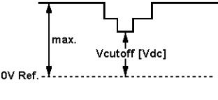
20.Measure the cut off pulse during first full line after the frame blanking (see Fig.
8-2). You will see two pulses, one being the cut off pulse and the other being the white drive pulse. Choose the one with the lowest value; this is the cut off pulse.
21.Select the cathode with the highest VDC value for the alignment. Adjust the V Cut-Off of this gun with the SCREEN potentiometer (see Fig. 8-1) on the LOT to the correct value (see table below).
22.Press the STATUS/EXIT button to display the SDAM onscreen display.
23.Press the MENU button to enter the normal user menu.
24.In the normal user menu, use the MENU UP/DOWN keys to highlight the
PICTURE sub menu (if necessary).
25.Press the MENU LEFT/RIGHT keys to enter the PICTURE sub menu.
26.Use the MENU UP/DOWN keys to select PICTURE.
27.Use the MENU LEFT/RIGHT keys to reset the value of PICTURE to the original
value.
28.Use the MENU UP/DOWN keys to select BRIGHTNESS.
29.Use the MENU LEFT/RIGHT keys to reset the value of BRIGHTNESS to the original value.
30.Press the MENU button twice to return to the top level SDAM menu.
31.Use the POWER button on the remote control transmitter or the POWER button on the television set to turn off the television set. This will save the changes made in SDAM.
Figure: V Cut-Off
Table: Cut-off Voltage, Large Screen
Screen Size |
Cut-off Voltage |
|
|
|
|
25/28Tesla, 25/28BLD |
+140V +/- 4V |
|
|
20RF/21RF/25RF/29RF,21RF Pin-Free, 25"HF LA, |
+145V +/- 4V |
25V/27V/32V/35V/25"/33"/28BLS, 29",29SF EU, |
|
|
|
21RF AP/CH, 25" AP/CH, 25RF/29RFAP/CH, 29SF AP |
+155V +/- 4V |
|
|
21RF Ph, 24/28/32WS BLD,29RF (Eu), 28/32WSRF |
+160V +/- 4V |
|
|
Focusing
1.Connect the RF output of a video pattern generator to the antenna input.
2.Input a circle or crosshatch test pattern to the television set.
3.Press the AUTO PICTURE button on the remote control transmitter repeatedly to choose PERSONAL or MOVIES picture mode.
4.Adjust the FOCUS potentiometer (see Fig. 8-1)until the vertical lines near the left and right sides of the screen, and near the horizontal center of the screen, are at minimum width without visible haze.
Software Alignments and Settings
The following options are performed in the Service Default Alignment Mode (SDAM).
SDAM is described in the "Service Modes, Error Codes and Fault Finding" section. The following alignments are explained:
1.OPTIONS
2.TUNER
3.WHITE TONE
4.GEOMETRY
5.AUDIO
Options
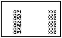
Figure: Options Menu
Options are used to control the presence or absence of certain features and hardware.
How to change an Option Byte
An Option Byte represents a number of different options. Changing these bytes directly makes it possible to set all options very quickly. All options are controlled via seven option bytes.
To change Option Byte(s):
1.Enter SDAM:
Press the following key sequence on the remote control transmitter: 0-6-2-5-9-6-MENU
Do not allow the display to time out between entries while keying the sequence.
2.Use the MENU UP/DOWN keys to highlight the OPTIONS sub menu.
3.Press the MENU LEFT or MENU RIGHT key to enter the OPTIONS sub menu.
4.In the OPTIONS sub menu, press the MENU UP/DOWN keys to select OP 1 through OP 7.
5.Use the number keys on the remote control transmitter to enter a new value for the selected option byte. The value must be entered as a three-digit value (for example, "4" would be entered as "0-0-4").
6.The selected value must be between 0 and 255.
7.When all desired changes to the option bytes are made, press the MENU button to return to the top level SDAM menu. This will save changes to the option byte settings.
8.To ensure the option byte changes take effect: Turn the television set OFF by
using the POWER button on the remote control transmitter or the local keyboard.
Disconnect the television set from AC power for at least ten seconds. Reconnect the television set to AC power. Turn the television set ON by using the POWER button on the remote control transmitter or the local keyboard.
T8 Option Byte Codes
MODEL |
|
|
OPTION BYTES |
|
|
||
|
OP1 |
OP2 |
OP3 |
OP4 |
OP5 |
OP6 |
OP7 |
20RF40 S321 |
* NOT |
AVAILABLE |
|
|
|
|
|
20RF40 S325 |
* NOT AVAILABLE |
|
|
|
|
||
20RF50 S321 |
0 |
23 |
129 |
162 |
252 |
152 |
0 |
20RF50 S325 |
0 |
23 |
129 |
162 |
252 |
152 |
0 |
21PT63 9A85 |
* NOT |
AVAILABLE |
|
|
|
|
|
21PT83 9B85 |
* NOT AVAILABLE |
|
|
|
|
||
25PS40 S321 |
0 |
23 |
1 |
1 |
144 |
153 |
0 |
25PS40 S325 |
0 |
23 |
1 |
1 |
144 |
153 |
0 |
25PS50 S321 |
0 |
23 |
1 |
162 |
252 |
152 |
0 |
26LL50 0131 |
16 |
23 |
1 |
1 |
144 |
153 |
0 |
26LW50 2231 |
16 |
23 |
1 |
162 |
252 |
152 |
0 |
27PS50 B321 |
0 |
23 |
1 |
162 |
252 |
152 |
0 |
27PS55 S321 |
0 |
23 |
1 |
162 |
252 |
152 |
0 |
27PS60 S321 |
0 |
23 |
1 |
162 |
253 |
152 |
0 |
27RF50 S325 |
0 |
23 |
129 |
162 |
252 |
152 |
0 |
27RF72 S325 |
* NOT |
AVAILABLE |
|
|
|
|
|
29LL60 0131 |
16 |
23 |
1 |
162 |
252 |
152 |
0 |
29LW60 2231 |
16 |
23 |
1 |
162 |
252 |
152 |
0 |
29PV70 2235 |
16 |
23 |
129 |
162 |
252 |
152 |
0 |
32PS55 S321 |
0 |
23 |
129 |
162 |
252 |
152 |
0 |
32PS60 B321 |
0 |
23 |
129 |
162 |
253 |
152 |
0 |
32PS61 S321 |
0 |
23 |
129 |
162 |
253 |
152 |
0 |
33LL80 1131 |
0 |
23 |
129 |
162 |
253 |
152 |
0 |
CH0119 C322 |
133 |
16 |
2 |
132 |
0 |
- |
- |
CH0127 C321 |
213 |
18 |
2 |
64 |
0 |
- |
- |
MS2530 C321 |
0 |
5 |
0 |
10 |
192 |
9 |
0 |
HC0113 C321 |
1 |
16 |
148 |
148 |
0 |
- |
- |
HC0119 C322 |
1 |
16 |
148 |
148 |
0 |
- |
- |
MS2530 C325 |
0 |
5 |
0 |
10 |
192 |
9 |
0 |
MS2730 C321 |
0 |
5 |
0 |
1 |
192 |
9 |
0 |
MS3250 C321 |
0 |
215 |
129 |
162 |
164 |
88 |
0 |
MS3650 C329 |
0 |
215 |
129 |
162 |
164 |
88 |
0 |
PA0113 C321 |
221 |
218 |
35 |
36 |
128 |
- |
- |
PA0132 C321 |
223 |
222 |
43 |
40 |
0 |
- |
- |
PC0119 C322 |
133 |
16 |
2 |
132 |
0 |
- |
- |
PC0125 C321 |
133 |
16 |
2 |
64 |
0 |
- |
- |
PC0127 C321 |
213 |
18 |
2 |
64 |
0 |
- |
- |
PCW227 C321 |
213 |
222 |
3 |
33 |
0 |
- |
- |
PCW227 S321 |
213 |
222 |
3 |
33 |
0 |
- |
- |
PL0119 C322 |
1 |
16 |
0 |
132 |
128 |
- |
- |
PL0125 C321 |
1 |
16 |
0 |
128 |
128 |
- |
- |
PL0127 C321 |
193 |
16 |
0 |
64 |
128 |
- |
- |
PLW225 S321 |
213 |
254 |
3 |
35 |
128 |
- |
- |
PPC132 C321 |
223 |
222 |
43 |
40 |
0 |
- |
- |
PPC132 C331 |
223 |
222 |
43 |
40 |
0 |
- |
- |
PPC136 C327 |
223 |
222 |
43 |
40 |
0 |
- |
- |
PRF227 S325 |
215 |
254 |
3 |
35 |
128 |
- |
- |
SC3127 N321 |
213 |
18 |
2 |
64 |
0 |
- |
- |
SC3132 N321 |
223 |
222 |
43 |
40 |
0 |
- |
- |
SC3132 N331 |
223 |
222 |
43 |
40 |
0 |
- |
- |
*Option Byte Data for these models was not available at manual release. Refer to future updates to this manual regarding these models.
Tuner
Note: Described alignments are only necessary when the NVM (part reference number7602) is replaced.
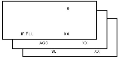
Figure: Tuner Menu
IF PLL
This adjustment is auto-aligned. Therefore, no action is required.
AGC (AGC take over point)
1.Connect the RF output of a video pattern generator to the antenna input.
2.Input a color bar test pattern to the television set.
3.Set the amplitude of the video pattern generator to 10 mV and set the frequency to 61.25 MHz (channel 3).
4.Connect a DC multimeter to pin 1 of the tuner(item 1000 on the main chassis).
5.Enter SDAM:
Press the following key sequence on the remote control transmitter: 0-6-2-5-9-6-MENU Do not allow the display to time out between entries while keying the sequence.
6.Use the MENU UP/DOWN keys to highlight the TUNER sub menu.
7.Press the MENU LEFT/RIGHT keys to enter the TUNER sub menu.
8.Use the MENU UP/DOWN keys to select AGC.
9.Use the MENU LEFT/RIGHT keys to adjust the AGC value (default value is 27) until the voltage at pin 1 of the tuner lies between 3.8V and 2.3V.
10.Press the MENU button to return to the top level SDAM menu.
11.To ensure the AGC change takes effect: Turn the television set OFF by using the
POWER button on the remote control transmitter or the local keyboard. Disconnect the television set from AC power for at least ten seconds. Reconnect the television set to AC power. Turn the television set ON by using the POWER button on the remote control transmitter or the local keyboard.
SL (Slicing Level)
This adjustment sets the sync slicing level for non-standard signals.
SL should be turned ON to help correct picture instability in premium decoded cable channels.
OFF: slicing level dependent on noise detector
ON: fixed slicing level of 70%
To adjust SL:
1.Enter SDAM:
Press the following key sequence on the remote control transmitter: 0-6-2-5-9-6-MENU Do not allow the display to time out between entries while keying the sequence.
2.Use the MENU UP/DOWN keys to highlight the TUNER sub menu.
3.Press the MENU LEFT/RIGHT keys to enter the TUNER sub menu.
4.Use the MENU UP/DOWN keys to select SL.
5.Use the MENU LEFT/RIGHT keys to toggle SL "Off" and "On"
6.Press the MENU button to return to the top level SDAM menu.
7.To ensure the SL setting is saved: Turn the television set OFF by using the
POWER button on the remote control transmitter or the local keyboard. Disconnect the television set from AC power for at least ten seconds. Reconnect the television set to AC power. Turn the television set ON by using the POWER button on the remote control transmitter or the local keyboard.
White Tone
Figure: White Tone Menu
The values of the black cut off level can be adjusted in the WHITE TONE sub menu. Normally, no alignment is needed for WHITETONE, and the given default values are used.
Default settings:
NORMAL (color temperature = 9600 K):
NORMAL RED = 40
NORMAL GREEN = 40
NORMAL BLUE = 40
To adjust NORMAL RED, NORMAL GREEN, and NORMAL BLUE:
1.Enter SDAM:
Press the following key sequence on the remote control transmitter: 0-6-2-5-9-6-MENU Do not allow the display to time out between entries while keying the sequence.
2.Use the MENU UP/DOWN keys to highlight the WHITE TONE sub menu.
3.Press the MENU LEFT/RIGHT keys to enter the WHITE TONE sub menu.
4.Use the MENU UP/DOWN keys to select NORMAL RED, NORMAL GREEN, or NORMAL BLUE.
5.Use the MENU LEFT/RIGHT keys to adjust the value of NORMAL RED, NORMAL GREEN, or NORMAL BLUE.
6.When all desired changes to the WHITE TONE submenu values are made, press the MENU button to return to the top level SDAM menu.
7.To ensure the WHITE TONE settings are saved: Turn the television set OFF by using the POWER button on the remote control transmitter or the local keyboard.
Disconnect the television set from AC power for at least ten seconds. Reconnect the television set to AC power. Turn the television set ON by using the POWER button on the remote control transmitter or the local keyboard.
Geometry
The geometry alignments menu contains several Items for correct picture geometry alignment.
1.Connect the RF output of a video pattern generator to the antenna input.
2.Input a crosshatch test pattern to the television set.
3.Set the amplitude of the video pattern generator to at least 1 mV and set the frequency to 61.25 MHz (channel 3).
4.Press the AUTO PICTURE button on the remote control transmitter repeatedly to choose PERSONAL or MOVIES picture mode.
5.Enter SDAM:
Press the following key sequence on the remote control transmitter: 0-6-2-5-9-6-MENU Do not allow the display to time out between entries while keying the sequence.
6.Use the MENU UP/DOWN keys to highlight the GEOMETRY sub menu.
7.Press the MENU LEFT/RIGHT keys to enter the GEOMETRY sub menu.
8.Use the MENU UP/DOWN keys to highlight either the HORIZONTAL sub menu or the VERTICAL sub menu.
9.Press the MENU LEFT/RIGHT keys to enter either the HORIZONTAL sub menu or the VERTICAL sub menu.
10.Use the MENU UP/DOWN keys to select items in the HORIZONTAL sub menu or the VERTICAL sub menu.
11.Use the MENU LEFT/RIGHT keys to adjust the values of items in the HORIZONTAL and VERTICAL sub menus.
12.When all desired changes to the HORIZONTAL and VERTICAL sub menu values are made, press the MENU button twice to return to the top level SDAM menu.
13.To ensure the GEOMETRY settings are saved: Turn the television set OFF by using the POWER button on the remote control transmitter or the local keyboard. Disconnect the television set from AC power for at least ten seconds. Reconnect the television set to AC power. Turn the television set ON by using the POWER button on the remote control transmitter or the local keyboard.
The following alignments can be performed in the GEOMETRY submenu:
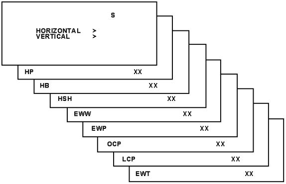
Figure: Horizontal Menu
Horizontal:
Horizontal Parallelogram (HP) Aligns straight vertical lines at the top and the bottom of the screen; vertical rotation round the center.
Horizontal Bow(HB) Aligns straight horizontal lines at the top and the bottom of the screen; horizontal rotation around the center.
Horizontal Shift(HSH) Aligns the horizontal center of the picture to the horizontal center of the CRT.
East West Width(EWW) Aligns the width of the picture.
East West Parabola(EWP) Aligns straight vertical lines at the sides of the screen.
Upper Corner Parabola (UCP) Aligns straight vertical lines in the upper corners of the screen.
Lower Corner Parabola (LCP) Aligns straight vertical lines in the lower corners of the screen.
East West Trapezium(EWT) Align straight vertical lines at the middle of the screen.
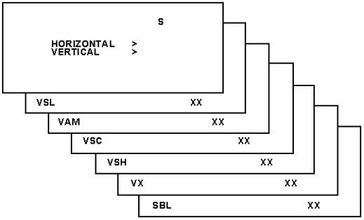
Figure: Vertical Menu
Vertical:
Vertical slope (VSL) Aligns the picture so the proportions are the same at the top and bottom of the screen. This alignment must be performed first, before all other vertical alignments. Turning SBL ON will assist in performing this alignment.
Vertical Amplitude(VAM) Aligns the height of the picture (other vertical alignments are NOT compensated).
Vertical S-Correction (VSC) Aligns the vertical linearity, so that the vertical intervals of the grid-patterns are the same over the entire height of the screen.
Vertical Shift(VSH) Aligns the vertical center of the picture to the vertical center of the CRT. After performing this alignment, it may be necessary to perform the
VAM alignment again.
Vertical Zoom(VX) Adjusts picture height.
Service blanking(SBL) Turns the blanking of the lower half of the screen ON or OFF (to be used in combination with the vertical slope alignment).
The table below lists the default GEOMETRY values for the different television sets.
Table: Default Geometry Values
Alignment |
Description |
20RFL260/37R |
21PT839B/85R |
27RFL260/37R |
20RFL250/37R |
21PT639A/85R |
|
|
BTSC |
BTSC DBX |
BTSC DBX |
BISONIC |
BISONIC |
|
|
NON-DBX |
|
|
|
|
|
|
|
|
|
|
|
HP |
Hor. Parallelogram |
31 |
33 |
33 |
31 |
33 |
|
|
|
|
|
|
|
HB |
Hor. Bow |
30 |
30 |
30 |
30 |
30 |
|
|
|
|
|
|
|
HSH |
Hor. S hift |
35 |
39 |
39 |
35 |
39 |
|
|
|
|
|
|
|
EWW |
East West Width |
34 |
35 |
35 |
34 |
35 |
|
|
|
|
|
|
|
EWP |
East West Parabola |
33 |
22 |
22 |
33 |
22 |
|
|
|
|
|
|
|
UCP |
Upper Corner |
35 |
41 |
41 |
35 |
41 |
|
Parabola |
|
|
|
|
|
|
|
|
|
|
|
|
LCP |
Lower Corner |
35 |
41 |
41 |
35 |
41 |
|
Parabola |
|
|
|
|
|
|
|
|
|
|
|
|
EWT |
East West |
43 |
31 |
31 |
43 |
31 |
|
Trapezium |
|
|
|
|
|
|
|
|
|
|
|
|
VSL |
Vert. Slope |
33 |
31 |
31 |
33 |
31 |
|
|
|
|
|
|
|
VAM |
Vert. Amplitude |
33 |
25 |
25 |
33 |
25 |
|
|
|
|
|
|
|
VSC |
Vert. S -correction |
32 |
35 |
35 |
32 |
35 |
|
|
|
|
|
|
|
VSH |
Vert. S hift |
35 |
21 |
21 |
35 |
21 |
|
|
|
|
|
|
|
VX |
Vert. Zoom |
33 |
25 |
25 |
33 |
25 |
|
|
|
|
|
|
|
Audio
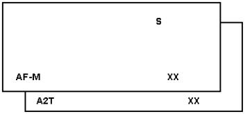
Figure: Audio Menu
No alignments are necessary for the AUDIO sub menu. Use the default values.
AF-M
Default value is 300.
A2T
TV A2 Threshold
Default value is 250.
To adjust AF-M:
1.Enter SDAM:
Press the following key sequence on the remote control transmitter: 0-6-2-5-9-6-MENU Do not allow the display to time out between entries while
 Loading...