


Service Manual
1st Release August 2001
|
|
Page |
Contents |
1 |
|
Foreword |
3 |
|
Notes on the sewing machine in relation to environment, handling, cleaning and safety |
5 |
|
Specifications off PFAFF machines |
6 |
|
Removing the housing covers |
8 |
|
Adjustment instructions |
|
|
Feeding system |
|
|
1. |
Adjustment of toothed belt tension |
13 |
2. |
Adjustment of feed dog in sideways direction on Pfaff 1520 |
14 |
3. |
Adjustment of feed dog in sideways direction on Pfaff 1530-1540 |
16 |
4. |
Adjustment of feed dog height |
18 |
5. |
Adjustment of presser bar height on Pfaff 1520 |
19 |
6. |
Adjustment of presser bar height on Pfaff 1530-1540 |
20 |
7. |
Adjustment of top feed foot in sewing direction |
22 |
8. |
Adjustment of top feed foot height |
24 |
9. |
Adjustment of feed regulator cranks on Pfaff 1520 / 1530 |
26 |
10. |
Adjustment of feed regulator cranks on Pfaff 1540 |
27 |
11. |
Zero point adjustment of stitch length regulator |
28 |
12. |
Timing of feed motion |
30 |
Automatic utility-stitch unit |
|
|
13. |
Replacing the automatic module on Pfaff 1520 - 1530 |
32 |
14. |
Adjustment of the locking disk |
34 |
15. |
Replacing the zigzag-stitch unit on Pfaff 1520 - 1530 |
35 |
16. |
Basic position of setting eccentric for the sideways needle position |
36 |
17. |
Adjustment of needle penetration in needle plate slot |
37 |
18. |
Adjustment of the sideways movement of the needle bar |
38 |
19. |
Adjustment of the stop for the left needle position |
40 |
20. |
Adjustment of the feed reversing bar |
42 |
21. |
Replacing the utility-stitch unit on Pfaff 1540 |
44 |
22. |
Adjustment of the gears in relation to each other |
46 |
23. |
Replacing the zigzag-stitch unit on Pfaff 1540 |
47 |
24. |
Basic position of setting eccentric for the sideways needle position on Pfaff 1540 |
48 |
25. |
Adjustment of needle penetration in needle plate slot on Pfaff 1540 |
49 |
26. |
Adjustment of the sideways movement of the needle bar on Pfaff 1540 |
50 |
27. |
Adjustment of zigzag stitch penetration in needle plate slot on Pfaff 1540 |
52 |
28. |
Adjustment of the stop for the left needle position on Pfaff 1540 |
53 |
Stitch forming parts (sewing hook) |
|
|
29. |
Adjustment of needle clearance in needle slot in sewing direction |
56 |
30. |
Adjustment of hook-to-needle clearance |
58 |
30a. |
Adjustment of bevel gears |
59 |
31. |
Sewing hook timing |
60 |
32. |
Adjustment of needle bar height |
62 |
33. |
Adjustment of bobbin case position finger |
63 |
1
Stitching off |
|
|
34. |
Adjustment of needle threader |
64 |
35. |
Adjustment of bobbin winder stop |
66 |
36. |
Adjustment of bobbin thread tension |
67 |
37. |
Adjustment of needle thread tension |
68 |
38. |
Adjustment of thread check spring stroke |
70 |
39. |
Adjustment of equal stitch length for left and right buttonhole seams |
72 |
40. |
Adjustment of equal forward and reverse stitch length |
73 |
|
(for forward and reverse controlled utility stitches) |
|
41. |
Making up a sewing sample |
74 |
Repair Instructions |
|
|
42. |
Removing and fitting the needle thread tension |
75 |
43. |
Changing the pressure spring in the handwheel release |
76 |
44. |
Removing and fitting the sewing hook |
78 |
45. |
Cleaning and oiling the machine |
78 |
46. |
Changing the toothed belt |
80 |
47. |
Adjusting the arm shaft crank |
82 |
48. |
Changing the bevel gears |
84 |
49. |
Changing the motor |
88 |
50. |
Changing the motor circuit board on motor types UUS 390 and UUS 393 |
90 |
51. |
Changing the carbon brushes on motor types UUS 390 and UUS 393 |
91 |
52. |
Changing the motor pinion |
92 |
53. |
Changing the motor toothed belt |
93 |
54. |
Changing the circuit board in foot control AE 010 |
94 |
55. |
Changing the mains connections in foot control AE 010 |
95 |
Safety test |
|
|
56. |
Electrical safety test |
96 |
57. |
Electrical safety test with ABB Metrawatt M 5013 |
96 |
58. |
Simulated leakage current measurements of complete motors with ABB Metrawatt M 5013 99 |
|
59. |
Measures required in case of incorrect readings |
99 |
2
Foreword
The purpose of this service manual is to assist you in quick and correct repair of the machines. Adjustments should only be made if the settings deviate from the requirements described in this manual.
When checking or adjusting a machine, always proceed in the order of the worksteps prescribed.
For easier reference, each workstep is identified by a number. Different operational procedures are indicated by a circle or a square.
The indications "left", "right", "top", "bottom", "front" and "back" always refer to the upright machine with the controls facing the operator.
When assembling dismantled machines, adjust the machine to approximately the right settings. This facilitates the subsequent fine adjustments.
Unless otherwise specified, the handwheel must always be turned forward.
When carrying out maintenance work on live parts or in their proximity, the machine is to be separated from the power supply by disconnecting the lead cord from the electrical socket.
An electrical safety test must be carried out after all repair work, even if the repair work is of a mechanical nature.
The required electrical tests for the appliances are laid down in the current EU regulations, EEC directives, and the EMC-law (Standard EN 60335-1/A: 96 = ICE 335-1: 91/A1:94, mod).
It is obligatory to perform a safety test in accordance with VDE 0701-1 after repair, modification and testing of electrical appliances.
Outside Germany there are similar regulations in force which are largely identical with the requirements of VDE 0701.
It is therefore necessary to consult a specialist when carrying out repairs on electrical appliances.
3
For the proper adjustment of the machine, the following gauges and tools are required:
z Needle rise gauge: . . . . . . . . . . . . . . . . . . . . . . . . . . . . . . . . . . . . . . |
.00-870136-01 |
z Needle rise clamp: . . . . . . . . . . . . . . . . . . . . . . . . . . . . . . . . . . . . . . . |
00-870137-01 |
z Spacer: . . . . . . . . . . . . . . . . . . . . . . . . . . . . . . . . . . . . . . . . . . . . . . . |
63-102600-18 |
z Adjustment gauge for the bobbin case holder: . . . . . . . . . . . . . . . . . . . |
00-880133-01 |
z Presser foot gauge: . . . . . . . . . . . . . . . . . . . . . . . . . . . . . . . . . . . . . . |
63-114690-39 |
z Ring-shaped open-end spanner 5.5 mm . . . . . . . . . . . . . . . . . . . . . . . |
43-111010-04 |
z Torx screwdriver TX 6 . . . . . . . . . . . . . . . . . . . . . . . . . . . . . . . . . . . . |
07-434008-40 |
z Torx screwdriver TX 10 . . . . . . . . . . . . . . . . . . . . . . . . . . . . . . . . . . . . |
07-434008-44 |
z Torx screwdriver TX 15 . . . . . . . . . . . . . . . . . . . . . . . . . . . . . . . . . . . . |
07-434008-45 |
z Torx screwdriver TX 20 . . . . . . . . . . . . . . . . . . . . . . . . . . . . . . . . . . . . |
07-434008-46 |
z Torx screwdriver TX 25 . . . . . . . . . . . . . . . . . . . . . . . . . . . . . . . . . . . . |
07-434008-47 |
z Torx offset screwdriver TX 15 . . . . . . . . . . . . . . . . . . . . . . . . . . . . . . . |
07-434008-74 |
z Circlip fitting tool 2.3 short . . . . . . . . . . . . . . . . . . . . . . . . . . . . . . . . . |
07-437003-20 |
z Circlip fitting tool 3.2 short . . . . . . . . . . . . . . . . . . . . . . . . . . . . . . . . . |
07-437003-30 |
z Circlip fitting tool 4.0 short . . . . . . . . . . . . . . . . . . . . . . . . . . . . . . . . . |
07-437003-40 |
z Circlip fitting tool 5.0 short . . . . . . . . . . . . . . . . . . . . . . . . . . . . . . . . . |
07-437003-50 |
z Circlip fitting tool 6.0 short . . . . . . . . . . . . . . . . . . . . . . . . . . . . . . . . . |
07-437003-60 |
z Circlip fitting tool 10.0 short . . . . . . . . . . . . . . . . . . . . . . . . . . . . . . . . . |
07-437003-86 |
z Spring hook . . . . . . . . . . . . . . . . . . . . . . . . . . . . . . . . . . . . . . . . . . . . |
07-437006-00 |
Subject to design and dimensional modifications.
4
Notes on the sewing machine in relation to environment, handling, cleaning and safety
Environment:
The recommended operating ranges are as follows:
Ambient temperature |
-10°C to 40°C (50° to 104°F) |
Air humidity |
20 % to 80 % |
This machine is a high-quality electro-mechanical device. It is designed for household purposes and should always be supervised when in use.
Make sure that it is not subjected to: dust, severe dampness, direct sunlight, static electricity, heat-produ- cing objects, corrosive chemicals or liquids.
To ensure adequate ventilation the machine should be placed unobstructed on a firm, even surface.
Handling:
Always protect the machine from damage caused by hitting or dropping.
Cleaning:
To clean the housing, use a dry, clean, soft, lint free cloth. To remove particularly persistent dirt, use a soft cloth with a neutral cleansing agent for plastic materials.
Please note!
Do not use any insecticides or chemical products such as petrol (gas) or liquid chemicals to clean the housing.
Safety:
1.The machine must be put into operation according to the indications on the specification plate.
2.Do not place any objects in the openings on the machine.
3.Do not use the sewing machine if:
-there is visible damage,
-its function is defective,
-it is wet, e.g. with condensation.
4.Do not pull the mains plug out of the socket by its cord.
5.If this appliance is used for another purpose than that intended, or if it is wrongly operated, we cannot accept any liability for any damage caused.
6.To avoid the risk of electric shock, do not open the machine. There are no parts inside the machine which the user can repair. This is solely the responsibility of our qualified service staff.
7.Be sure to use only original PFAFF parts.
5

Specifications of PFAFF machines
PFAFF 1540
Electronic free-arm utility stitch machine with 40 sewing programs (push buttons). A straight stitch program with 15 needle positions.
A zigzag program with 15 needle positions. A buttonhole program with adjustable width. 37 utility stitches.
High-ohm foot control (cold) with torque raising. Dual fabric feed. Needle threader.
PFAFF 1530
Electronic free-arm utility stitch machine with 15 sewing programs (program dial). A straight stitch program with 15 needle positions.
A zigzag program with 15 needle positions. A buttonhole program with adjustable width. 12 utility stitches.
High-ohm foot control (cold) with torque raising. Dual fabric feed.
PFAFF 1520
Electronic free-arm utility stitch machine with 15 sewing programs (program dial). A straight stitch program with 15 needle positions.
A zigzag program with 15 needle positions. A buttonhole program with adjustable width. 12 utility stitches.
High-ohm foot control (cold) with torque raising.
Detailed specifications of the machines
zElectronic free-arm utility stitch machine
zDirectly controlled automatic utility-stitch unit, step-down ratio 6:1 (1540)
zProgram selection by means of a program dial (1520/1530)
zUtility stitch width 5.5 mm
zStitch length from 0 to 6 mm
zReverse stitch length from 0 to 3 mm
zHigh-ohm foot control (cold)
zFM radio and TV screened, approval marking, suppression degree B
zSafety class II with GS test marking
zMaster switch for motor.
zGlare-free built-in sewing lamp 230V or 120V 15 W
zPendulum-type needle bar frame
zTransmission of drive from arm shaft to lower shaft by toothed belt, transmission ratio 1:1
zPower input rating: 90 W when sewing at 950 r.p.m.; 40W when stationary
6
zMaintenance-free PFAFF transverse double-rotating hook
zLink take-up lever
zLinkage-type feed regulator
zDual fabric feed
zDisengageable feed dog
zNeedle threader
zDrive from motor to handwheel by flat-toothed belt
z60-1000 stitches per minute
zSintered metal bearings
zOil for sintered metal bearings: BP Energol HLP 46 or HLP 80 No. 28-036550-09
zOil for sewing hook No. 91-129452-91
zClear workspace: 175, 114, 205 mm
zMachine height: 280 mm
zBaseplate dimensions: 390, 155 mm
zFree arm dimensions: 80, 49, 200 mm
zHousing material: lightweight metal
zWeight of sewing head: approx. 8 kg
zNeedle system 130/705 H
Additional needle system classifications:
Twin needle |
Suffix = Zwi |
|
|
|
Wing needle |
Suffix = Wing |
|
|
|
Twin hem stitching needle |
Suffix = Zwi-Ho |
|
|
|
Top stitch needle |
Suffix = N |
|
|
|
Stretch needle |
Suffix = PS |
|
|
|
Jeans needle |
Suffix = J |
|
|
|
Possible needle points: |
|
|
|
|
Small ball point |
Suffix = SES |
|
|
|
Medium ball point |
Suffix = SUK |
|
|
|
Large ball point |
Suffix = SKF |
|
|
|
Very pointed round point |
Suffix = J |
|
|
|
Leather point right hand |
Suffix = LR |
|
|
|
Specifications and versions of built-in motors in the PFAFF 1520-1540 |
|
|||
Type UUS 390 |
|
220-240V |
50/60Hz |
4500 r.p.m. |
No. 902-1039-001 |
|
27W |
|
|
Radioscreened according to EN 55014 |
Safety class II |
|
||
Type UUS 393 |
|
110-120V |
50/60Hz |
4500 r.p.m. |
No. 902-1039-003 |
|
27W |
|
|
Radioscreened according to EN 55014 |
Safety class II |
|
||
7

Removing the housing covers
Note:
Before adjusting or repairing the machine, make sure to remove the housing covers as described in this manual.
zDisconnect the machine's main plug.
zRemove needle and presser foot.
zRemove detachable work support.
zRemove top cover.
zSwitch on bobbin winder.
zRemove the two Torx screws of the housing insert..
zRemove housing insert.
zLay the machine on its back and remove the four fastening screws of the baseplate.
zRemove baseplate.
zRemove the two fastening screws 1 of free-arm cover (fig. 1).
zPull the left-hand side of the free-arm cover a little bit downwards and remove it towards the left.
zRemove needle plate.
zRemove the two fastening screws 2 of the upper free-arm cover (fig. 2).
zLoosen fastening screw 3 of free-arm cover.
zRemove free-arm cover.
8
zLoosen the fastening screws 4, 5, 6 and 7 of the rear housing shell (fig. 3 and 4).
zLoosen the snap connections by pressing with your thumb on the spots marked with arrows on the inner surface of the arm (fig. 5).
zRemove the rear housing shell.
zRemove motor cover.
9

zLoosen the fastening screws 8, 9, and 10 of the front housing shell (fig. 5 and 6).
zRemove fastening screws 10 and 11.
10
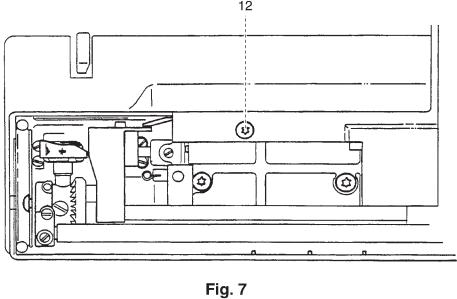
zRemove fastening screw 12 (fig. 7).
zSwitch on the top key row of the utility stitch unit.
zCarefully remove the front housing shell by lifting it off.
The assembly must be carried out in reverse order.
11
Notes:
12

Feeding system
1. Adjustment of the toothed belt tension
Requirement:
The toothed belt must be so taut that the sewing hook has no play in its direction of rotation. However, it must be possible to turn the machine easily.
Adjustment:
zLoosen screw 1 (fig. 1)
zRe-position tensioning roller 2 with a screwdriver as required.
zTighten screw 1.
Check:
zCheck adjustment according to the "Requirement".
zPress lightly against the middle of the toothed belt (250 g). The toothed belt should move forward by some 1 to 3 mm.
13
2. Adjustment of feed dog in sideways direction on Pfaff 1520
Requirement:
The left and right clearance of the feed dog in the feed slot must be the same (fig. 2).
Check:
Carry out a visual check of the feed dog position.
Adjustment:
zLoosen the two screws 3 and 4 (fig. 2a).
zLoosen screw 5.
zDetach spring 6.
zRe-position feed-dog driving shaft 7 with the two cylindrical pins 8 and 9 sideways until the feed dog is centered in the feed slot.
zFirmly tighten the two screws 3 and 4.
zPush bolt 11 against connecting bar 10.
zFirmly tighten screw 5.
zRe-attach spring 6.
Cross-check:
The feed dog must be exactly in the center of the feed slot. The feed driving shaft must not bind nor have any play.
14

15
3. Adjustment of feed dog in sideways direction on Pfaff 1530-1540
Requirement:
The left and right clearance of the feed dog in the feed slot must be the same (fig. 3).
Check:
Carry out a visual check of the feed dog position.
Adjustment:
zLay the machine on its back.
zLoosen screw 12 (fig. 4).
zRemove bolt 13 to the right.
zLoosen screw 5.
zRemove circlip 14.
zRemove bolt 11.
zLoosen both screws 3 and 4.
zRe-position feed-dog driving shaft 7 with the two cylindrical pins 8 and 9 sideways until the feed dog is centered in the feed slot.
zFirmly tighten the two screws 3 and 4.
zDetach spring 6.
zRemove the needle plate.
zPull the feed dog forward with one finger and release.
zThe complete feed-dog driving shaft 7 must slide lightly back.
zLoosen screw 15 (fig. 5).
zMove the top feed lever forwards and backwards.
zThe top feed should move freely without any difficulty (if necessary, remove cause of binding).
zFit bolt 13 with the washer located to the left of pull-rod 18, and ensure that it is free from play (fig. 4).
zMove the complete top feed lever forwards and backwards.
zMake sure that both top and bottom feed move smoothly and without any difficulty.
zTighten screw 12 and check once again for ease of operation.
zMove crank pin 16 with pull-rod 17 to the side in such a way that both top and bottom feed can move easily.
zTighten screw 15 and check once again for ease of operation.
zFit bolt 11.
zInsert circlip 14.
zPush bolt 11 against connecting bar 10.
zTighten screw 5.
zRe-attach spring 6.
Cross-check:
The feed dog must be exactly in the center of the feed slot.
Both top and bottom feed must not bind nor have any play.
16

17
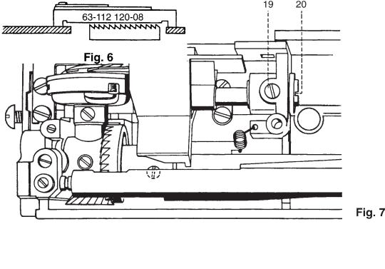
4. Adjustment of feed dog height
Requirement:
At the highest working position of the feed dog, the tips of the feed dog teeth must protrude above the needle plate surface by 0.9 mm (fig. 6).
Check:
zRemove the needle.
zRemove the presser foot.
zSet the maximum stitch length.
zPlace bridge gauge (63-112120-08) over the feed dog onto the needle plate.
zTurn the handwheel until the feed dog has reached its highest working position.
zCarry out a visual check.
zThe feed dog must not touch the gauge, but must clear it by 0.1 mm.
Adjustment:
zLoosen screw 19 by just 1/8 of a turn (fig 7).
zTurn eccentric stud 20 until the eccentric is facing the rear part of the housing (basic position)
zTurn the eccentric stud to the left until the feed dog height is properly set.
zTighten screw 19.
Cross-check
zTurn the handwheel and check the feed dog height at its highest working position.
zMake sure that the feed-dog lowering mechanism neither binds nor hits against anything when the handwheel is turned.
zLower feed dog and check the function.
18
5. Adjustment of presser bar height on Pfaff 1520
Requirement:
With the presser bar lifter raised, there must be a clearance of 8 mm between the needle plate and the bottom of the zigzag foot.
Check:
zRaise the presser bar lifter.
zFit the zigzag foot.
zLower the feed dog.
zFully raise the presser bar lifter and hold it there firmly.
zAt the same time, insert presser foot gauge No. 63-114690-39 from the rear under the zigzag foot and into the cutouts of the needle plate (fig. 8).
zLower the presser bar lifter to its normal position again.
The zigzag foot must rest parallel and without play on the presser foot gauge.
However, the presser foot gauge must not lift the zigzag foot, and the needle thread tension release 23 must be without play.
Adjustment:
zLoosen screw 21 (fig. 9)
zWith the presser bar lifter raised turn the zigzag foot until it is parallel to the sides of the presser foot gauge.
zUse a screwdriver to press presser bar guide 22 firmly downward.
zAt the same time, firmly tighten screw 21.
Cross-check:
zPush the presser bar lifter further upward and release it again.
The zigzag foot must rest parallel and without play on the presser foot gauge.
Needle thread tension release must be without play. The presser bar lifter must be in raised.
19
6. Adjustment of presser bar height on Pfaff 1530-1540
Requirement:
With the presser bar lifter raised, there must be a clearance of 8 mm between the needle plate and the bottom of the zigzag foot.
Check:
zRaise the presser bar lifter.
zFit the zigzag foot.
zLower the feed dog.
zFully raise the presser bar lifter and hold it there firmly.
zAt the same time, insert presser foot gauge No. 63-114690-39 from the rear under the zigzag foot and into the cutouts of the needle plate (fig. 9).
zLower the presser bar lifter to its normal position again.
The zigzag foot must rest parallel and without play on the presser foot gauge.
However, the presser foot gauge must not lift the zigzag foot, and the needle thread tension release 23 must be without play (fig. 10).
Adjustment:
zLoosen the three screws 21, 24 and 25.
zWith the presser bar lifter raised turn the zigzag foot until it is parallel to the sides of the presser foot gauge.
zUse a screwdriver to press presser bar guide 22 firmly downward.
zAt the same time, firmly tighten screw 21.
Cross-check:
zPush the presser bar lifter further upward and release it again.
The zigzag foot must rest parallel and without play on the presser foot gauge.
Needle thread tension release 23 must be without play. The presser bar lifter must be in raised position.
Note:
Tighten the two screws 24 and 25 later, when the top feed foot height is adjusted.
20

21
7. Adjustment of top feed foot in sewing direction
Requirement:
The front edge of the top feed foot must be between the first and second tooth point of the center tooth row of the feed dog (fig. 11).
Check:
zRaise the presser bar lifter.
zRemove presser foot & presser foot holder.
zSet the maximum stitch length.
zEngage the top feed foot.
zTurn the handwheel until the rising feed dog is flush with the needle plate surface.
zLower the presser bar lifter.
zCarry out a visual check.
Adjustment:
zLoosen screw 26 (fig. 12).
zRaise the presser bar lifter until the top feed foot is just resting on top of the feed dog.
zAt the same time push the top feed dog to the front or to the rear until its front edge is between the first and second tooth point of the center tooth row.
zLower the presser bar lifter.
zTighten screw 26, making sure that driving shaft 27 has no play.
Cross-check:
z Check as described under "Check".
22

23
8. Adjustment of top feed foot height
Requirement:
At its highest working position the top feed foot must be 2 mm higher than the lower edge of the zigzag foot (fig. 13).
Note:
This adjustment must only be carried out when the height of the presser bar is set correctly!
Check:
zRaise the presser bar lifter.
zFit the zigzag foot.
zEngage the top feed.
zTurn the handwheel until the needle bar is at its lowest position. Caution: The handwheel must now no longer be turned!
zLower the feed dog.
zFully raise the presser bar lifter and hold it in this position.
zAt the same time, insert presser foot gauge No. 63-114690-35 from the rear under the zigzag foot and into the cutouts of the needle plate.
zLower the presser bar lifter to its raised position again.
zPress the top feed foot 28 about 2 mm upward against the pressure of the spring and release it.
zCheck that the top feed foot rests only lightly on the presser foot gauge and has no play.
Adjustment:
zLoosen screws 24 and 25.
zPush counter bearing 29 lightly downward until the top feed foot 28 rests lightly on the presser foot gauge.
zTighten screw 24 in this position.
Cross-check:
zCheck for light resting and freedom of play of the top feed foot on the presser foot gauge as described under "Check".
Adjusting the guide piece:
zFully raise the presser bar lifter and hold it in this position.
zRemove the presser foot gauge.
zLower the presser bar lifter to its raised position again.
zTurn the handwheel until needle bar 30 is in its top position.
24

zSet guide piece 31 at a clearance of 0.2 mm from cross head 32 (fig. 14).
zTighten screw 25.
Cross-check:
z Turn the handwheel and check for clearance of 0.2 mm.
25

9. Adjustment of feed regulator cranks on Pfaff 1520 / 1530
Requirement:
The feed regulator cranks must not have any axial play.
Check:
Move the feed regulator cranks laterally backwards and forwards (fig. 15).
Adjustment:
zLoosen the two screws 5.
zPush feeding eccentric 33 to the right against the bearing.
zPush bolt 11 to the right until connecting bar 10 is in contact with edge 34 of feeding eccentric 33.
zTighten the screws 5.
Cross-check:
zSet the stitch length graduated dial to "6".
zDetach spring 35.
zCheck the joints for easy movement and lack of play.
zRe-attach spring 35.
26

10. Adjustment of feed regulator cranks on Pfaff 1540
Requirement:
The feed regulator cranks must not have any axial play.
Check:
Move the feed regulator cranks laterally backwards and forwards (fig. 16).
Adjustment:
zLoosen the two screws 5 and 36.
zPush feeding eccentric 33 to the right against the bearing.
zPush bolt 11 to the right until connecting bar 10 is in contact with edge 34 of feeding eccentric 33.
zPush the circlip along with shaft 37 and tooth segment 38 along with actuating crank 39 to the left until no crank or joint has any play anymore.
zTighten screws 5 and 36.
Cross-check:
zSet the stitch length graduated dial to "6".
zDetach spring 35.
zCheck the joints for easy movement and lack of play.
zRe-attach spring 35.
27

11. Zero point adjustment of stitch length regulator
Requirement:
When the stitch length graduated dial is set to "0", the feed dog should only move up and down.
Check:
zSet the stitch length graduated dial to "0".
zPlace a piece of fabric under the presser foot.
zLower the presser foot.
zOperate the machine.
The fabric must not be fed neither forwards nor backwards.
Precondition 1:
The dot markings on the toothed segments must be diametrically opposite each other (fig. 17).
Precondition 2:
Eccentric 40 must be in its basic position facing upwards (fig. 18).
Adjustment:
zLoosen screw 41 with a 5.5 mm spanner.
zRe-position screw 41 until the center lines of the bolts in actuating crank 39 and linkage 42 and rod 43 are level (see dot-dash line).
zTighten screw 41.
Cross-check:
z As described under "Check".
28
 Loading...