


-948/26
Supplement to the instruction
manual and parts list for the
series 1180, 3701, 5483
296-12-18 959/002 engl. 06.09
The reprinting, copying or translation of PFAFF Instruction Manuals, whether in whole or in part, is only permitted with our previous authorization and with written reference to the source.
PFAFF Industriesysteme und Maschinen AG
Hans-Geiger-Str. 12 - IG Nord
D-67661 Kaiserslautern

|
|
Index |
|
Contents ................................................................................................. |
Page |
1 |
Proper use........................................................................................................................... |
4 |
1.01 |
Using standard presser feet ................................................................................................. |
4 |
2 |
Controls .............................................................................................................................. |
5 |
2.01 |
Puller functions .................................................................................................................... |
5 |
2.02 |
Aligning the puller ................................................................................................................ |
5 |
2.03 |
Control panel ........................................................................................................................ |
6 |
2.03.01 |
Screen displays .................................................................................................................... |
6 |
2.03.02 |
Function keys ....................................................................................................................... |
6 |
2.03.03 |
Selecting and altering parameters ........................................................................................ |
9 |
2.03.04 |
Selecting the user level ...................................................................................................... |
10 |
3 |
Commissioning ................................................................................................................ |
11 |
3.01 |
Basic position of the machine drive ................................................................................... |
11 |
3.02 |
Testing the function of the start inhibitor ........................................................................... |
12 |
4 |
Setting up ......................................................................................................................... |
13 |
4.01 |
Entering the puller feed stroke (stitch length) .................................................................... |
13 |
4.02 |
Setting the puller pressure ................................................................................................. |
13 |
4.03 |
Entering the maximum speed ............................................................................................ |
14 |
4.04 |
Entering the start and end backtacks ................................................................................. |
14 |
4.05 |
Setting the stitch counting function for the bobbin thread control ..................................... |
15 |
5 |
Sewing ................................................................................................................................ |
1 |
5.01 |
Manual sewing ..................................................................................................................... |
1 |
5.02 |
Programmed sewing ............................................................................................................ |
2 |
5.03 |
Error messages .................................................................................................................... |
3 |
6 |
Parameter Settings........................................................................................................... |
16 |
7 |
Software-Update .............................................................................................................. |
21 |
8 |
Reset / Kaltstart ................................................................................................................ |
22 |
9 |
Partslist ............................................................................................................................. |
23 |
10 |
Circuit diagrams ............................................................................................................... |
24 |

Proper use
1 Proper use
With the puller the workpiece is fed continously, which makes it possible to sew to a great extent without shifting and puckering. The puller’s linear motor enables an individual clearance space between the needle plate and the puller roller.
All adjustments, such as e.g. puller feed stroke, puller roller clearance etc. are carried out by altering the parameter values, see Chapter 2.03.03 Selecting and altering parameters.
Any use of these machines which is not approved by the manufacturer shall be considered as improper use! The manufacturer shall not be liable for any damage arising out of improper use! Proper use shall also be considered to include compliance with the operation, adjustment, service and repair measures speci-
fied by the manufacturer!
1.01 Using standard presser feet
2 |
1 |
3 |
1 mm |
Fig. 1 - 01 |
●With the adapter 1 which belongs to the accessories, standard presser feed can also be used
(Ordering number 91-154 790-22).
●Mount adapter 1 as shown in Fig. 1-01.
●Loosen screw 2 and push puller arm 3 back.
●Screw the presser foot onto adapter 1.
●Adjust puller arm 3 so that there is a clearance of approx. 1 mm between the puller roller and the presser foot.
●Tighten screw 2.
When using the adapter, the height of the puller roller must be adjusted as described in
Chapter 2.02.
4

|
|
Controls |
2 |
Controls |
|
2.01 |
Puller functions |
|
|
|
Engaging/disengaging the puller |
|
|
● Raise the puller drive unit 1 until it locks |
|
|
into place and swing puller arm 2 back as |
|
|
far as possible. To engage the puller, |
|
|
follow the instructions in the reverse |
|
|
order. |
|
|
Switching the puller on/off |
|
|
● The puller is automatically switched on or |
|
|
off when the puller unit is engaged or |
|
1 |
disengaged. |
|
|
|
|
2 |
Setting the puller feed motion |
|
|
● The feed motion of the puller is set by |
|
|
means of parameters (see Chap. 1.06 |
|
|
Parameter settings and the Motor |
|
Fig. 2 - 01 |
Instruction Manual) |
|
|
2.02 |
Aligning the puller |
|
2 |
|
3 |
|
1 |
|
Fig. 2 - 02 |
Puller crosswise to sewing direction
●Loosen screw 1.
●Align puller 2 to the seam.
●Tighten screw 1.
Height of the puller roller
●Loosen screw 3
●Align puller 2, so that there is a clearance of approx. 0.3 mm between the puller roller 4 and the cloth plate.
●Tighten screw 3.
4
5

Controls
2.03 |
Control panel |
1 |
3 |
2 |
||
|
|
|
|
|
|
|
|
|
|
Speed
4000 PUL 30%
2.0mm
4
The control panel consists of display 1 and the function keys described below. Display 1 consists of a two-row, alpha-numerical display with 16 symbols per row. The texts 3 show the respective status of the function keys and the operating modes of the machine. During the power-on phase the control panel automatically switches on all LCD segments and the horn. The number of the version of the installed software then appears on the display, until the higher-ranking control unit sends commands to the control panel.
2.03.01 Screen displays
●Activated functions are displayed with a triangular marking 2 below or next to the respective function key.
●In the sewing mode all relevant sewing data is displayed and these can be changed directly, depending on the status of the machine, see also Chapter 5 Sewing.
●During the parameter input the selected parameter number with the corresponding value is displayed, see Chapter 2.02.03 Selecting/changing parameters.
2.03.02 Function keys
The function keys described below are used basically to switch machine functions on and off.
If a corresponding value has to be set for the activated function, this is carried out with the corresponding +/- key. By pressing and holding the corresponding +/- key, the appropriate numerical value 4 is changed slowly to begin with. If the corresponding +/- key is held down longer, the values change more quickly.
Start backtacks
If this key is pressed, the backtacks at the beginning of the seam (start backtacks) are switched on or off. The number of forward stitches (A) or reverse stitches (B) for the start backtacks can be changed by pressing the +/- key underneath. To convert from double backtack to single backtack set the corresponding number of stitches at zero.
6

Controls
End backtacks
●If this key is pressed, the backtacks at the end of the seam (end backtacks) are switched on or off. The number of reverse stitches (C) or forward stitches (D) can be changed by pressing the +/- key underneath. To convert from double backtack to single backtack set the corresponding number of stitches at zero.
Needle position
●If this key is pressed the corresponding function is switched on or off. When the function is switched on, the needle positions at t.d.c. after sewing stops.
Foot position after stop
●If this key is pressed the corresponding function is switched on or off. When the function is switched on, the presser foot is raised after sewing stops.
Foot position after trimming
●If this key is pressed the corresponding function is switched on or off. When the function is switched on, the presser foot is raised after thread trimming.
Thread trimmer
● If this key is pressed the thread trimming function is switched on or off.
Speed (only in programmed sewing)
●If this key is pressed the corresponding function is switched on or off. In the seam program the speed is not dependent on the pedal. When the function is switched on, the speed cannot be adjusted by pedal. Sewing can only be carried out at the set maximum speed.
●If the function is switched off, the speed up to maximum speed is adjusted by the pedal.
Reverse sewing
●If this key is pressed the corresponding function is switched on or off. When the function is switched during programmed sewing, the corresponding seam section is sewn in reverse.
Manual seam (only in programmed sewing)
●If this key is pressed the machine switches to manual sewing. When the function is switched on, the move to the next seam section is not carried out by stitch counting or sensor, but manually with the use of the pedal (position "-2").
Stop
●If this key is pressed the corresponding function is switched on or off. When the function is switched on, the machine stops automatically at the end of a seam section.
Sensor
●In manual sewing the number of compensating stitches from the point where the photocell is light to the end of the seam can be set under parameter 111, and in programmed sewing directly.
7

Controls
Stitch counting
●If this key is pressed the corresponding function is switched on or off. When the function is switched on, the machine moves to the next seam section after sewing the number of stitches entered.
TE/Speed
●In the programmed sewing mode, the number of stitches is entered by stitching them off.
●If this key is pressed once, the machine changes to parameter input.
●If this key is pressed twice (within 5 seconds) the machine changes to stitch input.
Scrolling
●If this key is pressed in the programmed sewing mode, the machine scrolls through the input menus on the display.
PM
●If this key is pressed the programmed sewing function is switched on or off. When the function is switched on, the letters "PM" appear on the display of the control panel. The parameters related to the program are shown in the alpha-numerical part of the display.
F1
No function assigned
F2
No function assigned
F3
No function assigned
F4
No function assigned
8
Controls
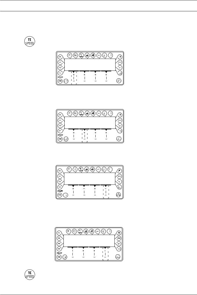
2.03.03 Selecting and altering parameters
● Switch on the machine.
● Press the TE/Speed key to call up the parameter input function.
TE |
|
No |
VAL |
A 101 |
OFF |
No ● By pressing the corresponding +/- key select the desired parameter group, e.g. "600".
TE
No
A 600
No ● By pressing the corresponding +/- key select the desired parameter, e.g. "660" for the
bobbin thread monitoring function.
TE |
|
No |
VAL |
A 660 |
1 |
VAL ● By pressing the corresponding +/- key set the desired value for the parameter selected, e.g. "2" for the "bobbin rest thread counter on" function.
TE |
|
No |
VAL |
A 660 |
2 |
● Press the TE/Speed key to take over the value and change to the sewing mode.
9
Controls
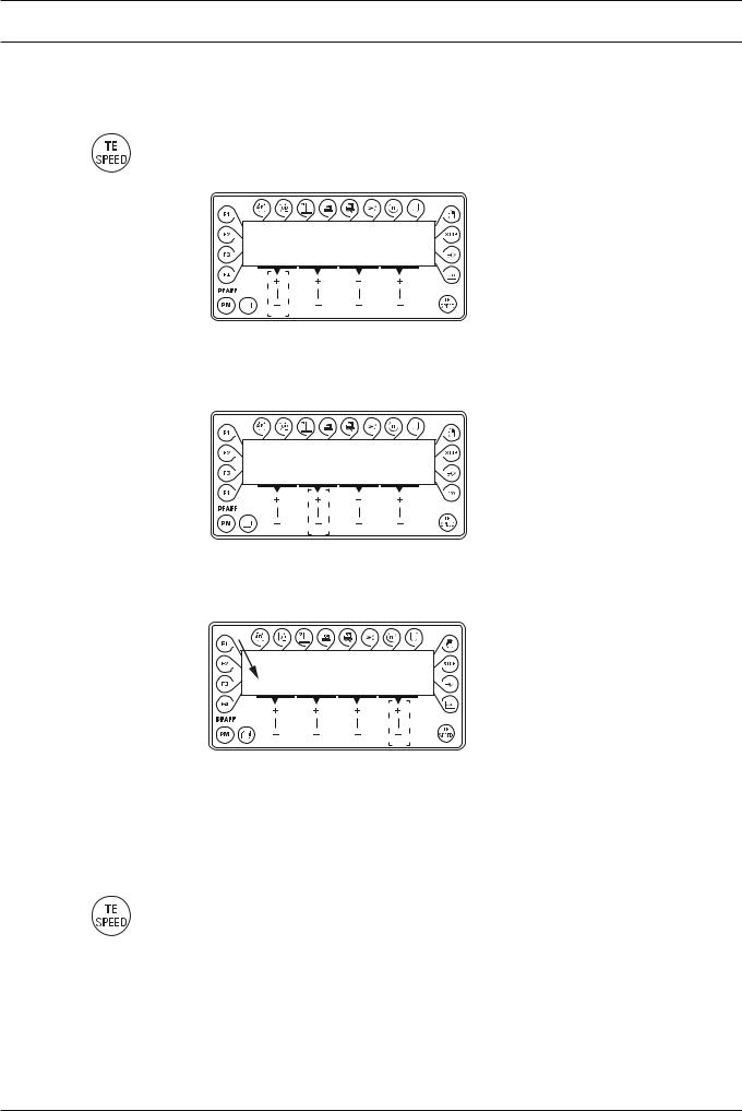
2.03.04 Selecting the user level
● Switch on the machine.
● Press the TE/Speed key to call up the parameter input function.
TE
No
A 101
No ● By pressing the corresponding +/- key select the parameter group "700".
TE
No
A 798 0
No ● By pressing the corresponding +/- key select the parameter "798".
TE |
|
No |
VAL |
B 798 |
1 |
VAL ● By pressing the corresponding +/- key select the desired user level: "0" = operator level A
"1" = technician level B
"11" = service level C
The respective level is displayed on the screen. (see arrow)
● Press the TE/Speed key to take over the value and change to the sewing mode.
10
 Loading...