


INSTRUCTION
CO2 Incubator
MCO-80IC
49

CONTENTS
INTRODUCTION |
|
|
P. 2 |
PRECAUTIONS FOR SAFE OPERATION |
|
P. 3 |
|
LABELS ON THE UNITS |
|
|
P. 6 |
ENVIRONMENTAL CONDITIONS |
|
|
P. 7 |
INCUBATOR COMPONENTS |
|
|
P. 8 |
Control panel and keypad |
|
|
P. 11 |
Remote alarm terminal |
|
|
P. 13 |
INSTALLATION SITE |
|
|
P. 14 |
INSTALLATION |
|
|
P. 15 |
Connection of CO2 gas cylinder |
|
|
P. 16 |
PREVENT CONTAMINATION |
|
|
P. 17 |
CAUTIONS FOR CULTURE |
|
|
P. 18 |
START-UP OF UNIT |
|
|
P. 19 |
SETTING OF CHAMBER TEMPERATURE AND CO2 DENSITY |
P. 20 |
||
KEY LOCK FUNCTION |
|
|
P. 23 |
ALARMS SAFETY FUNCTIONS |
|
P. 24 |
|
SETTING OF ALARM RESUME TIME |
|
P. 26 |
|
Operation after power failure |
|
|
P. 26 |
ROUTINE MAINTENANCE |
|
|
P. 27 |
Sterilizing of chamber and attachments |
|
P. 27 |
|
Filling the humidifying pan |
|
|
P. 29 |
CALIBRATION |
|
|
P. 30 |
Temperature calibration |
|
|
P. 30 |
CO2 calibration |
|
|
P. 30 |
TROUBLESHOOTING |
|
|
P. 31 |
DISPOSAL OF UNIT |
|
|
P. 33 |
AUTOMATIC CO2 CYLINDER CHANGEOVER |
|
P. 38 |
|
SPECIFICATIONS |
|
|
P. 39 |
PERFORMANCE |
|
|
P. 40 |
SAFETY CHECK SHEET |
|
|
P. 41 |
1 |
|
50 |
|

INTRODUCTION
ŶRead this manual carefully before using the appliance and follow the instructions for safety operation.
ŶSanyo never guarantee any safety if the appliance is used for any objects other than intended use or used by any procedures other than those mentioned in this manual.
ŶKeep this manual in an adequate place to refer to it as necessary.
ŶThe contents of the manual will be subjected to change without notice due to the improvement of performance or functions.
ŶContact Sanyo sales representative or agent if any page of the manual is lost or page order is incorrect.
ŶContact Sanyo sales representative or agent if any point in this manual is unclear or if there are any inaccuracies.
ŶNo part of this manual may be reproduced in any form without the expressed written permission of Sanyo.
51 |
|
2 |
|
PRECAUTIONS FOR SAFE OPERATION
It is imperative that the user complies with this manual as it contains important safety advice.
Items and procedures are described so that you can use this unit correctly and safely. If the precautions advised are followed, this will prevent possible injury to the user and any other person.
Precautions are illustrated in the following way:
 WARNING
Failure to observe WARNING signs could result in a hazard to personnel possibly resulting in serious injury or death.
 CAUTION
Failure to observe CAUTION signs could result in injury to personnel and damage to the unit and associated property.
Symbol shows;
this symbol means caution.
this symbol means an action is prohibited.
this symbol means an instruction must be followed.
Be sure to keep this manual in a place accessible to users of this unit.
< Label on the unit >
This mark is labeled on the cover in which the electrical components of high voltage are enclosed to prevent the electric shock.
The cover should be removed by a qualified engineer or a service personnel only.
 WARNING
As with any equipment that uses CO2 gas, there is a likelihood of oxygen depletion in the vicinity of the equipment. It is important that you assess the work site to ensure there is suitable and sufficient ventilation. If restricted ventilation is suspected, then other methods of ensuring a safe environment must be considered. These may include atmosphere monitoring and warning devices.
3 |
|
52 |
|

PRECAUTIONS FOR SAFE OPERATION
 WARNING
Do not use the unit outdoors. Current leakage or electric shock may result if the unit is exposed to rain water.
Only qualified engineers or service personnel should install the unit. The installation by unqualified personnel may cause electric shock or fire.
Install the unit on a sturdy floor and take an adequate precaution to prevent the unit from  turning over. If the floor is not strong enough or the installation site is not adequate, this may result
in injury from the unit falling or tipping over.
Never install the unit in a humid place or a place where it is likely to be splashed by water. Deterioration of the insulation may result which could cause current leakage or electric shock.
 Never install the unit in a flammable or volatile location. This may cause explosion or fire.
Never install the unit where acid or corrosive gases are present as current leakage or electric shock may result due to corrosion.
Always ground (earth) the unit to prevent electric shock. If the power supply outlet is not grounded, it will be necessary to install a ground by qualified engineers.
Never ground the unit through a gas pipe, water main, telephone line or lightning rod. Such grounding may cause electric shock in the case of an incomplete circuit.
Connect the unit to a power source as indicated on the rating label attached to the unit. Use of any other voltage or frequency other than that on the rating label may cause fire or electric shock.
Never store volatile or flammable substances in this unit if the container cannot be sealed. These may cause explosion or fire.
Do not insert metal objects such as a pin or a wire into any vent, gap or any outlet on the unit. This may cause electric shock or injury by accidental contact with moving parts.
Use this unit in safe area when treating the poison, harmful or radiate articles. Improper use may cause bad effect on your health or environment.
Turn off the power switch (if provided) and disconnect the power supply to the unit prior to 

 any repair or maintenance of the unit in order to prevent electric shock or injury.
Do not touch any electrical parts (such as power supply plug) or operate switches with a wet hand. This may cause electric shock.
53 |
|
4 |
|
PRECAUTIONS FOR SAFE OPERATION
 WARNING
Ensure you do not inhale or consume medication or aerosols from around the unit at the time of maintenance. These may be harmful to your health.
 Never splash water directly onto the unit as this may cause electric shock or short circuit.
Never put containers with liquid on the unit as this may cause electric shock or short circuit when the liquid is spilled.
Never bind, process, or step on the power supply cord, or never damage or break the power supply plug. A broken supply cord or plug may cause fire or electric shock.
 Do not use the supply cord if its plug is loose. Such supply cord may cause fire or electric shock.
Never disassemble, repair, or modify the unit yourself. Any such work carried out by an unauthorized person may result in fire, or electric shock or injury due to a malfunction.
Disconnect the power supply plug if there is something wrong with the unit. Continued  abnormal operation may cause electric shock or fire.
When removing the plug from the power supply outlet, grip the power supply plug, not the cord. Pulling the cord may result in electric shock or fire by short circuit.
Disconnect the power supply plug before moving the unit. Take care not to damage the power 

 cord. A damaged cord may cause electric shock or fire.
Disconnect the power plug when the unit is not used for long periods. Keeping the connection 

 may cause electric shock, current leakage, or fire due to the deterioration of insulation.
If the unit is to be stored unused in an unsupervised area for an extended period, ensure that children do not have access and that doors cannot be closed completely.
The disposal of the unit should be accomplished by appropriate personnel. Remove doors to prevent accidents such as suffocation.
 Do not put the packing plastic bag within reach of children as suffocation may result.
5 |
|
54 |
|

PRECAUTIONS FOR SAFE OPERATION
 CAUTION
Use a dedicated power source (a dedicated circuit with a breaker) as indicated on the rating label attached to the unit. A branched circuit may cause fire resulting from abnormal heating.
Connect the power supply plug to the power source firmly after removing the dust on the plug. A dusty plug or improper insertion may cause a heat or ignition.
Never store corrosive substances such as acid or alkali in this unit if the container cannot be sealed. These may cause corrosion of inner components or electric parts.
Check the setting when starting up of operation after power failure or turning off of power switch. The stored items may be damaged due to the change of setting.
 Be careful not to tip over the unit during movement to prevent damage or injury.
Prepare a safety check sheet when you request any repair or maintenance for the safety of service personnel.
LABELS ON THE UNIT
Some warning and/or caution labels are attached on the unit. Following shows the description of such labels.
This label is on the cover in which the electrical components of high voltage are enclosed to prevent the electric shock. The cover should be removed by a qualified engineer or a service personnel only.
This symbol means UV caution.
This symbol means attention or refer to document.
This symbol means hot surface.
This symbol means earth.
This symbol means power switch “ON”.
This symbol means power switch “OFF”.
55 |
|
6 |
|

ENVIRONMENTAL CONDITIONS
This equipment is designed to be safe at least under the following conditions (based on the IEC-1010-1):
ŶIndoor use;
ŶAltitude up to 1000 m;
ŶAmbient temperature 20oC to 35oC
ŶMaximum relative humidity 80% for temperature up to 31oC decreasing linearly to 50% relative humidity at 40oC;
Ŷ Mains supply voltage fluctuations not to exceed 10% of the nominal voltage;
Ŷ Other supply voltage fluctuations as stated by the manufacturer;
Ŷ Transient overvoltages according to Installation Categories (Overvoltage Categories) II; For mains supply the minimum and normal category is II;
Ŷ Pollution degree 2 in accordance with IEC 664.
7 |
|
56 |
|

INCUBATOR COMPONENTS
6 (inner face of ceiling)
7,8
Rear upper side
12
10 1
|
9 |
11 |
5 |
|
3
4
Upper left side
16 |
28 |
15 |
13, 14 |
2
Lower chamber |
When the bottom lid is removed |
||
|
|
|
|
21 |
22 |
20 |
18,19 |
17 |
23 |
24 |
27 |
25 |
26 |
57 |
|
8 |
|

INCUBATOR COMPONENTS
1.Outer door: Sticks to frame with magnetic seal. Door heater is installed in the door panel. The door window is double glass. The door opening is reversible. Contact Sanyo representative or agent to change the door hinge from left to right or vice versa.
2.Leveling foot: Screw type for adjusting the height. Adjust the foot so that the unit can be level.
3.Tray: Can be pulled toward you.
4.Tray support: Can be removed by lifting the front side and pulling toward you.
5.Side duct: Flow path for circulating air. Removable.
6.Fan (inner face of ceiling)
7.Sample air outlet: This also functions as an internal gas outlet. Normally, cover this outlet with the sample air outlet cap.
8.Sample air outlet cap: Always attach this cap except at the time of using of sample air outlet.
9.Door switch: Detects the door opening/closing and stops the circulating fan and electromagnetic valve for CO2 when door is open. UV lamp is also deactivated by door opening (when an optional UV system kit MCO-80UVS is installed).
10.Inside power outlet: AC 115 V and up to 3 A in total. It is possible to use on the condition that inner temperature below 40 oC and humidity below 50%R.H. At the first time to operate, press the reset button between two inside power outlets.
11.Access port: When not in use, cap them with two attached silicon caps on outside.
12.Connecting port for CO2 gas pipe (rear side): When an optional component MCO-80GC (automatic CO2 cylinder changeover system) is installed, both A and B are available. If MCO-80GC is not used, only A is available. Refer to page 16 for gas cylinder connection. Ensure that the gas pressure is set at 0.1 MPaG (1.0 kgf/cm2G, 14.5 psiG). Refer to page 38 for automatic CO2 cylinder changeover system.
13.Power switch: Main switch of the unit. Also functions as an over-current breaker.
14.Power switch cover: Power switch is covered by a switch cover to prevent the accidental push. To turn on or off the switch, remove the switch cover by loosening the screw.
15.Remote alarm terminal: Refer to page 13.
16.Outer power outlet: AC 115 V, and up to 3 A in total.
17.Bottom lid: Prevents UV light being exposed to the chamber. Just lift to remove for cleaning. See page 27 for details.
18.Water supply inlet cover: When filling the pan, remove a screw and rotate the cover.
19.Water supply inlet: Usually closed with water supply inlet cover.
20.Drain valve: Open the drain valve to drain water from the humidifying pan.
21.Drain outlet: Insert the drain outlet into the attached drain tank installed under the unit.
22.Drain tank
23.Front panel lower cover: Detach it when draining water from the humidifying pan. See to page 27 for details.
24.Humidifying pan: Use sterile distilled water of approximately 20 L to fill the pan.
25.Water level sensor for humidifying pan: Detects the water level in the humidifying pan.
9 |
|
58 |
|
INCUBATOR COMPONENTS
26.Auto water supply inlet: When an optional component MCO-80AS (automated water supply system kit) is installed, water is supplied from here.
27.UV lamp (option)
28. Fuse: upper: for inside power outlet |
125 V, 3.15 A. Normal blow type. |
lower: for outer power outlet |
125 V, 1 A. Normal blow type. |
59 |
|
10 |
|
INCUBATOR COMPONENTS
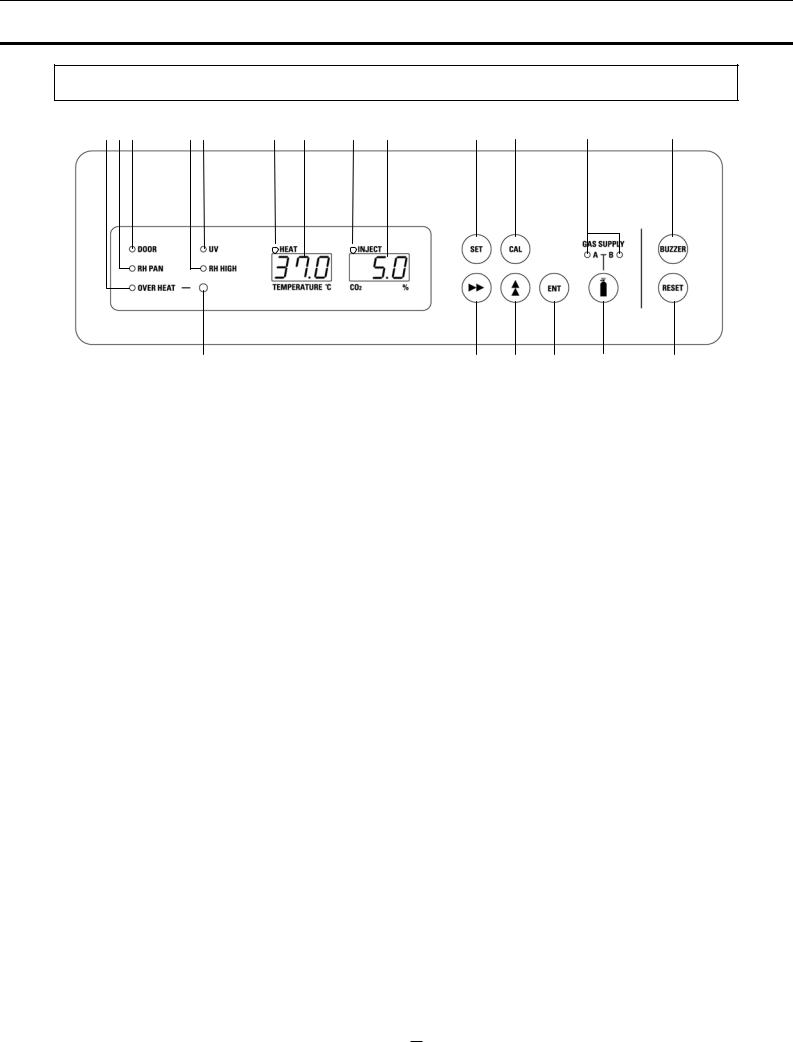
Control panel and keypad
9 8 7 |
6 5 |
2 |
1 |
4 |
3 |
11 |
12 |
14 |
13 |
10 |
19 |
18 |
17 |
15 |
16 |
1.Digital temperature indicator (TEMPERATURE oC): Normally, this indicator shows the chamber temperature. In the setting mode, it shows the set value of the chamber temperature. If the self diagnostic function detects any abnormality, an error code will be displayed.
2.Heater lamp (HEAT): This lamp lights when the heater is energized.
3. Digital CO2 density indicator (CO2 %): Normally, this indicator shows the CO2 concentration in the chamber. In the setting mode, it indicates the set value of the CO2 concentration.
4.CO2 inject lamp (INJECT): This lamp lights when CO2 gas is being injected.
5.UV indicator (UV): This lamp lights when the UV lamp is ON [when an optional component MCO-80UVS (UV system kit) is installed]. The blink of this indicator recommends the replacement of UV lamp.
6.High humidity mode indicator (RH HIGH): This lamp lights when the high humidity mode is activated. See page 21 for changing to the high humidity mode.
7.Door lamp (DOOR): This lamp lights when the outer door is open.
8.Water level alarm lamp (RH PAN): This lamp flashes when the water in the humidifying pan is less than approximately 5 liters.
9.Over heat lamp (OVER HEAT): This lamp lights when the chamber temperature reaches the upper limit set value. It starts to blink when the chamber temperature is back in below the upper limit set value.
10.Upper limit regulator: This regulator is used to set the upper temperature limit.
11.Set key (SET): Pressing this key to enter the setting mode, and the digits to be set will flash.
12.Calibration key (CAL): By pressing this key for approximately 5 seconds, the unit enters calibration function mode.
13.Alarm buzzer stop key (BUZZER): Press this key to silence the buzzer when the alarm operates and the buzzer sounds.
14.CO2 gas supply line indicator (A/B): The lamp for the supply line currently in use lights up provided that MCO-80GC automatic CO2 cylinder changeover system is installed.
15.CO2 gas supply line switching key : This key to select CO2 gas supply line is available only when an automatic CO2 cylinder changeover system MCO-80GC (option) is installed. When one CO2 cylinder is empty, the CO2 is supplied by the other cylinder automatically.
16.Upper limit alarm reset key (RESET): Press this key while the over heat lamp blinks to reset the alarm.
17.Enter key (ENT): Pressing this key memorizes the set value in the controller.
11 |
|
60 |
|

INCUBATOR COMPONENTS
Control panel and keypad
18.Numerical value shift key ( ): Pressing this key in the setting mode causes the numerical value to shift. In key lock mode, pressing this key makes key lock ON or OFF.
19.Digit shift key ( ): Pressing this key in the setting mode causes the changeable digit to shift. Pressing this key more than 5 seconds enters key lock mode. See page 23 for the key lock.
61 |
|
12 |
|
 Loading...