


Instruction Manual
AC Servo Motor and Driver
MINAS A4P Series
•Thank you for buying and using Panasonic AC Servo Motor and Driver, MINAS A4P Series.
•Read through this Instruction Manual for proper use, especially read "Precautions for Safety" ( P.8 to 11) without fail for safety purpose.
•Keep this Manual at an easily accessible place so as to be referred anytime as necessary.
DV0P4490

Content
[Before Using the Products]
page
Safety Precautions .................................................................... |
8 |
Maintenance and Inspection................................................... |
12 |
Introduction.............................................................................. |
14 |
Outline .......................................................................................................................................................... |
14 |
On Opening the Package ............................................................................................................................. |
14 |
Check of the Driver Model ............................................................................................................................ |
14 |
Check of the Motor Model ............................................................................................................................ |
15 |
Check of the Combination of the Driver and the Motor ................................................................................ |
16 |
Parts Description ..................................................................... |
18 |
Driver ............................................................................................................................................................ |
18 |
Motor............................................................................................................................................................. |
20 |
Console......................................................................................................................................................... |
21 |
Installation................................................................................ |
22 |
Driver ............................................................................................................................................................ |
22 |
Motor............................................................................................................................................................. |
24 |
Console......................................................................................................................................................... |
26 |
[Preparation] |
page |
System Configuration and Wiring .......................................... |
28 |
Overall Wiring (Connecting Example of C-frame, 3-phase)......................................................................... |
28 |
Overall Wiring (Connecting Example of E-frame) ........................................................................................ |
30 |
Driver and List of Applicable Peripheral Equipments ................................................................................... |
32 |
Wiring of the Main Circuit (A to D-frame) ..................................................................................................... |
34 |
Wiring of the Main Circuit (E and F-frame)................................................................................................... |
35 |
Wiring to the Connector, CN X6 (Connection to Encoder) ........................................................................... |
38 |
Wiring to the Connector, CN X3 and 4 |
|
Wiring to the Connector, CN X7 (Connection to External Scale) ................................................................. |
40 |
Wiring to the Connector, CN X5 (Connection to Host Controller) ................................................................ |
41 |
Wiring for Connector CN X5 ......................................................................................................................... |
42 |
Interface Circuit ............................................................................................................................................ |
43 |
List of Signal for Connector CN X5 .............................................................................................................. |
44 |
Setup with the Front Panel...................................................... |
48 |
Composition of Touch Panel and Display..................................................................................................... |
48 |
Initial Status of the Front Panel Display (7-Segment LED) .......................................................................... |
48 |
Output Signals (Analog) and Their Functions .............................................................................................. |
49 |
Built-in Holding Brake ............................................................. |
50 |
Dynamic Brake......................................................................... |
52 |
[Setting] |
page |
Parameter Setup ...................................................................... |
56 |
Outline of Parameter .................................................................................................................................... |
56 |
How to Set .................................................................................................................................................... |
56 |
How to Connect ............................................................................................................................................ |
56 |
Composition of Parameters .......................................................................................................................... |
57 |
2

List of Servo Parameter ................................................................................................................................ |
58 |
List of 16-bit Positioning Parameters ........................................................................................................... |
73 |
List of 32-bit Positioning Parameters ........................................................................................................... |
77 |
List of Step Parameters ................................................................................................................................ |
77 |
Setup of Torque Limit.................................................................................................................................... |
78 |
How to Use the Console.......................................................... |
80 |
Setup with the Console ................................................................................................................................ |
80 |
Initial Status of the Console Display (7 Segment LED)................................................................................ |
80 |
Mode Change ............................................................................................................................................... |
81 |
Monitor Mode................................................................................................................................................ |
82 |
Teaching Mode ............................................................................................................................................. |
87 |
Parameter setup mode ................................................................................................................................. |
91 |
EEPROM Writing Mode ................................................................................................................................ |
96 |
Auto-Gain Tuning Mode ............................................................................................................................... |
97 |
Auxiliary Function Mode ............................................................................................................................... |
98 |
Copying Function (Console Only) .............................................................................................................. |
101 |
Outline of Setup Support Software, "PANATERM®" ........... |
103 |
Using BeforeProducts the
Preparation
Setting
Outline of PANATERM® .............................................................................................................................. |
103 |
How to Connect .......................................................................................................................................... |
103 |
[Operation Setting] |
page |
Overview of Operation Setting.............................................. |
106 |
Step Operation ....................................................................... |
107 |
Step Operation ........................................................................................................................................... |
107 |
Example of Incremental Operation Setting ................................................................................................ |
108 |
Example of Absolute Operation Setting ..................................................................................................... |
109 |
Example of Rotary Axis Operation Setting ................................................................................................. |
110 |
Example of Dwell Timer Operation Setting ................................................................................................ |
111 |
Jog Operation ........................................................................ |
112 |
Jog Operation ............................................................................................................................................. |
112 |
Homing ................................................................................... |
114 |
Homing Operation ...................................................................................................................................... |
114 |
Home Sensor + Z Phase (based on the front end) .................................................................................... |
116 |
Home Sensor (based on the front end) ...................................................................................................... |
117 |
Home sensor + Z phase (based on the rear end) ...................................................................................... |
118 |
Limit Sensor + Z phase .............................................................................................................................. |
120 |
Limit Sensor................................................................................................................................................ |
121 |
Z Phase Homing ......................................................................................................................................... |
122 |
Bumping Homing ........................................................................................................................................ |
122 |
Data Set ...................................................................................................................................................... |
123 |
Homing Offset Operation ............................................................................................................................ |
124 |
Emergency Stop Operation/Deceleration-and-Stop Operation ..... |
125 |
Temporary Stop Operation.................................................... |
126 |
Block Operation ..................................................................... |
127 |
Overview of Block Operation ...................................................................................................................... |
127 |
Continuous Block Operation....................................................................................................................... |
127 |
Combined Block Operation ........................................................................................................................ |
128 |
Sequential Operation............................................................. |
130 |
S-shaped Acceleration/Deceleration Function .................... |
131 |
OperationSetting
Adjustment
Whenin Trouble
Supplement
3

Timing Chart .......................................................................... |
132 |
Operation Timing after Power-ON .............................................................................................................. |
132 |
When an Error (Alarm) Has Occurred (at Servo-ON Command) .............................................................. |
133 |
When an Alarm Has Been Cleared (at Servo-ON Command) ................................................................... |
134 |
Servo-ON/OFF Action While the Motor Is at Stall (Servo-Lock) ................................................................ |
135 |
Servo-ON/OFF Action While the Motor Is in Motion .................................................................................. |
135 |
Absolute System ................................................................... |
136 |
Overview of Absolute System..................................................................................................................... |
136 |
Configuration of Absolute System .............................................................................................................. |
136 |
Battery (for Backup) Installation ................................................................................................................. |
136 |
Setup (Initialization) of Absolute Encoder .................................................................................................. |
136 |
Outline of Full-Closed Control .............................................. |
140 |
What Is Full-Closed Control ? .................................................................................................................... |
140 |
[Adjustment] |
page |
Gain Adjustment .................................................................... |
142 |
Real-Time Auto-Gain Tuning Mode....................................... |
144 |
Adaptive Filter............................................................................................................................................. |
147 |
Normal Mode Auto-Gain Tuning ........................................... |
148 |
Release of Automatic Gain Adjusting Function .................. |
151 |
Manual Gain Tuning (Basic) .................................................. |
152 |
Adjustment in Position Control Mode ......................................................................................................... |
153 |
Adjustment in Full-Closed Control Mode.................................................................................................... |
154 |
Gain Switching Function............................................................................................................................. |
155 |
Suppression of Machine Resonance ......................................................................................................... |
158 |
Manual Gain Tuning (Application) ........................................ |
160 |
Instantaneous Speed Observer.................................................................................................................. |
160 |
Damping Control......................................................................................................................................... |
161 |
[When in Trouble]
page
When in Trouble..................................................................... |
164 |
What to Check ? ......................................................................................................................................... |
164 |
Protective Function (What is Error Code ?) ............................................................................................... |
164 |
Protective Function (Detail of Error Code) ................................................................................................. |
165 |
Troubleshooting .................................................................... |
172 |
Motor Does Not Run / Motor Stops During an Operation .......................................................................... |
172 |
Point Deviates / Positioning Accuracy is Poor ........................................................................................... |
173 |
Home position Slips .................................................................................................................................... |
173 |
Abnormal Motor Noise or Vibration ............................................................................................................ |
173 |
Overshoot/Undershoot / Overheating of the Motor (Motor Burn-Out)........................................................ |
174 |
Parameter Returns to Previous Setup ....................................................................................................... |
174 |
Display of "Communication port or driver cannot be detected" Appears on the Screen While Using the |
|
PANATERM®. .............................................................................................................................................. |
174 |
4

[Supplement] |
page |
Conformity to EC Directives and UL Standards .................. |
176 |
Options ................................................................................... |
180 |
Recommended components................................................. |
191 |
Dimensions (Driver)............................................................... |
192 |
Dimensions (Motor) ............................................................... |
195 |
Permissible Load at Output Shaft ........................................ |
210 |
Motor Characteristics (S-T Characteristics) ........................ |
211 |
Motor with Gear Reducer ...................................................... |
217 |
Dimensions/Motor with Gear Reducer ................................. |
218 |
Permissible Load at Output Shaft/Motor with Gear Reducer ........ |
220 |
Characteristics of Motor with Gear Reducer ....................... |
221 |
Block Diagram of Driver ....................................................... |
222 |
Block Diagram by Control Mode........................................... |
224 |
Specifications (Driver)........................................................... |
226 |
Default Parameters (for all the models of A4P Series) .... |
228 |
Using BeforeProducts the
Preparation
Setting
Setting |
Operation |
Adjustment
Whenin Trouble
Supplement
5
6

[Before Using the Products]
|
page |
Safety Precautions .................................................... |
8 |
Maintenance and Inspection .................................. |
12 |
Introduction ............................................................. |
14 |
Outline ......................................................................................... |
14 |
On Opening the Package ............................................................ |
14 |
Check of the Driver Model........................................................... |
14 |
Check of the Motor Model ........................................................... |
15 |
Check of the Combination of the Driver and the Motor ............... |
16 |
Parts Description .................................................... |
18 |
Driver ........................................................................................... |
18 |
Motor ........................................................................................... |
20 |
Console ....................................................................................... |
21 |
Installation ............................................................... |
22 |
Driver ........................................................................................... |
22 |
Motor ........................................................................................... |
24 |
Console ....................................................................................... |
26 |
7

Safety Precautions Observe the Following Instructions Without Fail
Observe the following precautions in order to avoid damages on the machinery and injuries to the operators and other personnel during the operation.
• In this document, the following symbols are used to indicate the level of damages or injuries which might be incurred by the misoperation ignoring the precautions.
DANGER |
Indicates |
a |
potentially |
hazardous |
situation |
which, |
if |
not |
avoided, will result in death or serious injury. |
|
|
|
|||||
|
|
|
|
|
|
|
|
|
CAUTION |
Indicates |
a |
potentially |
hazardous |
situation |
which, |
if |
not |
avoided, will result in minor injury or property damage. |
|
|||||||
|
|
|
|
|
|
|
|
|
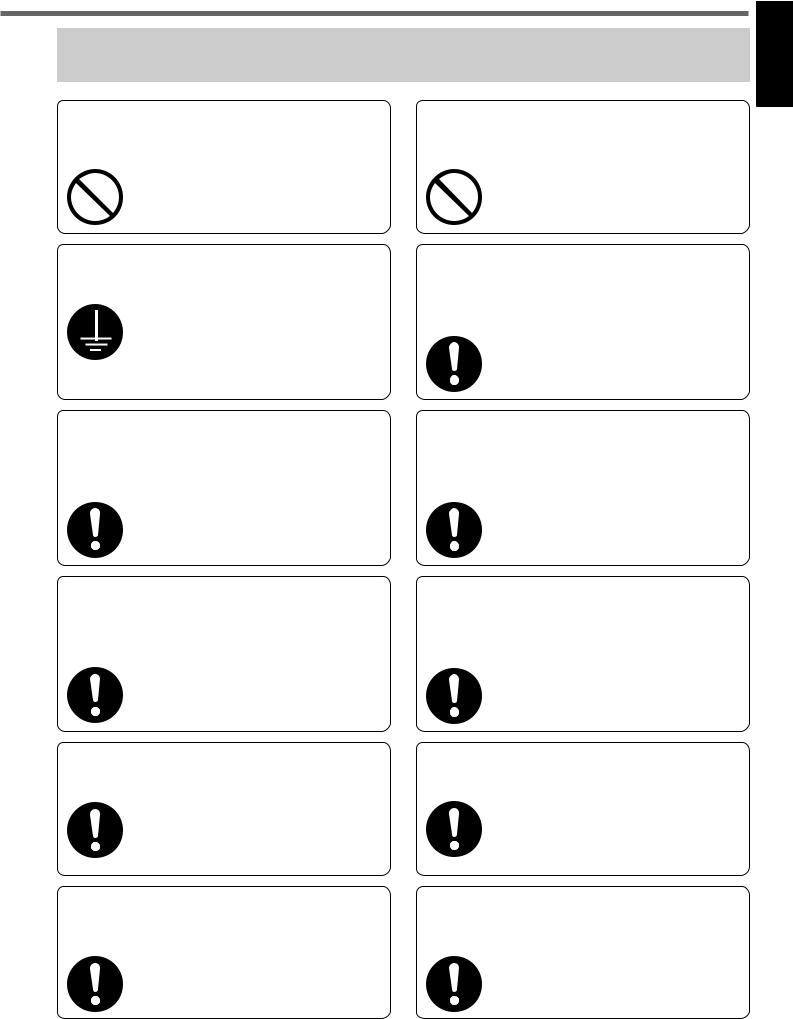
• The following symbols represent "MUST NOT" or "MUST" operations which you have to observe. (Note that there are other symbols as well.)
Represents "MUST NOT" operation which is inhibited.
Represents "MUST" operation which has to be executed.
 DANGER
Do not subject the Product to water, corrosive or flammable gases, and combustibles.
Failure to observe this instruction could result in fire.
Do not put your hands in the servo driver.
Failure to observe this instruction could result in burn and electrical shocks.
Do not drive the motor with external power.
Failure to observe this instruction could result in fire.
Do not subject the cables to excessive force, heavy object, or pinching force, nor damage the cables.
Failure to observe this instruction could result in electrical shocks, damages and breakdowns.
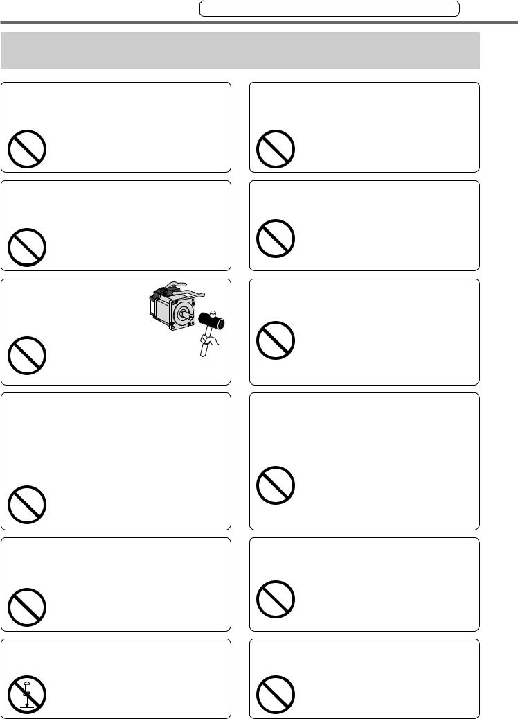
Do not touch the rotating portion of the motor while it is running.
Rotating portion 

Failure to observe this instruction could result in injuries.
Do not touch the motor, servo driver and external regenerative resistor of the driver, since they become very hot.
Failure to observe this instruction could result in burns.
8
[Before Using the Products]
 DANGER
Do not place combustibles near by the motor, driver and regenerative resistor.
Failure to observe this instruction could result in fire.
Do not place the console close to a heating unit such as a heater or a large wire wound resistor.
Failure to observe this instruction could result in fire and breakdowns.
Using Before Products the
Ground the earth terminal of the motor and driver without fail.
Failure to observe this instruction could result in electrical shocks.
Install an overcurrent protection, earth leakage breaker, over-tem- perature protection and emergency stop apparatus without fail.
Install an emergency stop circuit externally so that you can stop the operation and shut off the power immediately.
|
Failure to observe this instruction could |
|
result in injuries, electrical shocks, fire, |
|
breakdowns and damages. |
Install and mount the Product and machinery securely to prevent any possible fire or accidents incurred by earthquake.
Failure to observe this instruction could result in electrical shocks, injuries and fire.
Turn off the power and wait for a longer time than the specified time, before transporting, wiring and inspecting the driver.
Failure to observe this instruction could result in electrical shocks.
Turn off the power and make it sure that there is no risk of electrical shocks before transporting, wiring and inspecting the motor.
Check and confirm the safety of the operation after the earthquake.
Failure to observe this instruction could result in electrical shocks, injuries and fire.
Mount the motor, driver and regenerative resistor on incombustible material such as metal.
Failure to observe this instruction could result in fire.
Wiring has to be carried out by the qualified and authorized specialist.
Failure to observe this instruction could result in electrical shocks.
Make the correct phase sequence of the motor and correct wiring of the encoder.
Failure to observe this instruction could result in injuries breakdowns and damages.
9
Safety Precautions Observe the Following Instructions Without Fail
 CAUTION
Do not hold the motor cable or motor shaft during the transportation.
Failure to observe this instruction could result in injuries.
Never run or stop the motor with the electro-magnetic contactor installed in the main power side.
Failure to observe this instruction could result in breakdowns.
Do not give strong impact shock to
the motor shaft.
Failure to observe this  instruction could result
in breakdowns.
Do not approach to the machine since it may suddenly restart after the power resumption. Design the machine to secure the safety for the operator even at a sudden restart.
Failure to observe this instruction could result in injuries.
Do not use the built-in brake as a "Braking" to stop the moving load.
Failure to observe this instruction could result in injuries and breakdowns.
Do not modify, disassemble nor repair the Product.
Failure to observe this instruction could result in fire, electrical shocks and injuries.
Do not block the heat dissipating holes or put the foreign particles into them.
Failure to observe this instruction could result in electrical shocks and fire.
Do not step on the Product nor place the heavy object on them.
Failure to observe this instruction could result in electrical shocks, injuries, breakdowns and damages.
Do not turn on and off the main power of the driver repeatedly.
Failure to observe this instruction could result in breakdowns.
Do not make an extreme gain adjustment or change of the drive. Do not keep the machine running/operating unstably.
Failure to observe this instruction could result in injuries.
Do not give strong impact shock to the Product.
Failure to observe this instruction could result in breakdowns.
Do not pull the cables with excessive force.
Failure to observe this instruction could result in breakdowns.
10
[Before Using the Products]
 CAUTION
Use the motor and the driver in |
Make a wiring correctly and |
||
the specified combination. |
securely. |
|
|
Failure to |
observe this |
Failure to |
observe this |
instruction |
could result in |
instruction |
could result in |
fire. |
|
fire and electrical shocks. |
|
Using Before Products the
Use the eye bolt of the motor for transportation of the motor only, and never use this for transportation of the machine.
Failure to observe this instruction could result in injuries and breakdowns.
Make an appropriate mounting of the Product matching to its wight and output rating.
Failure to observe this instruction could result in injuries and breakdowns.
Keep the ambient temperature below the permissible temperature for the motor and driver.
Failure to observe this instruction could result in breakdowns.
Connect the brake control relay to the relay which is to shut off at emergency stop in series.
Failure to observe this instruction could result in injuries and breakdowns.
When you dispose the batteries, observe any applicable regulations or laws after insulating them with tape.
Observe the specified mounting method and direction.
Failure to observe this instruction could result in breakdowns.
Observe the specified voltage.
Failure to observe this instruction could result in electrical shocks, injuries and fire.
Execute the trial run without connecting the motor to the machine system and fix the motor. After checking the operation, connect to the machine system again.
Failure to observe this instruction could result in injuries.
When any error occurs, remove the cause and release the error after securing the safety, then restart.
Failure to observe this instruction could result in injuries.
This Product shall be treated as Industrial Waste when you dispose.
11
Maintenance and Inspection
• Routine maintenance and inspection of the driver and motor are essential for the proper and safe operation.
Notes on Maintenance and Inspection
1)Turn on and turn off should be done by operators or inspectors themselves.
2)Internal circuit of the driver is kept charged with high voltage for a while even after power-off. Turn off the power and allow 15 minutes or longer after LED display of the front panel has gone off, before performing maintenance and inspection.
3)Disconnect all of the connection to the driver when performing megger test (Insulation resistance measurement) to the driver, otherwise it could result in breakdown of the driver.
Inspection Items and Cycles
General and normal running condition
Ambient conditions : 30˚C (annual average), load factor of 80% or lower, operating hours of 20 hours or less per day.
Perform the daily and periodical inspection as per the items below.
Type |
Cycles |
Items to be inspected |
|
|
|
|
|
|
|
• Ambient temperature, humidity, speck, dust or foreign object |
|
|
|
• Abnormal vibration and noise |
|
|
|
• Main circuit voltage |
|
|
|
• Odor |
|
Daily |
Daily |
• Lint or other particles at air holes |
|
inspection |
• Cleanness at front portion of the driver and connecter |
||
|
|||
|
|
• Damage of the cables |
|
|
|
• Loose connection or misalignment between the motor and |
|
|
|
machine or equipment |
|
|
|
• Pinching of foreign object at the load |
|
|
|
|
|
|
|
• Loose tightening |
|
Periodical |
|
||
• Trace of overheat |
|||
Annual |
|||
inspection |
|||
|
• Damage of the terminals |
||
|
|
||
|
|
|
<Note> Inspection cycle may change when the running conditions of the above change.
12

[Before Using the Products]
Guideline for Parts Replacement
Use the table below for a reference. Parts replacement cycle varies depending on the actual operating conditions. Defective parts should be replaced or repaired when any error have occurred.
Using Before Products the
|
Disassembling for inspection and repair should be carried |
Prohibited |
out only by authorized dealers or service company. |
|
|
|
|
Product |
Component |
|
|
|
Standard replacement |
|
Note |
|
||
|
|
|
cycles (hour) |
|
|
|||||
|
|
|
|
|
|
|
|
|
|
|
|
|
|
|
|
|
|
|
|
|
|
|
Smoothing capacitor |
|
|
|
Approx. 5 years |
|
|
|
|
|
|
Cooling fan |
|
|
|
|
2 to 3 years |
|
|
|
|
|
|
|
|
(10,000 to 30,000 hours) |
|
|
|
|
||
|
|
|
|
|
|
|
|
|
||
|
Aluminum electrolytic |
|
|
|
|
|
|
|
||
|
|
|
Approx. 5 years |
|
|
|
|
|||
capacitor (on PCB) |
|
|
|
|
|
|
|
|||
|
|
|
|
|
|
|
|
|||
|
|
|
|
|
|
|
|
|
||
Driver |
|
|
|
|
|
Approx. 100,000 times |
|
|
|
|
|
Rush current |
|
|
|
|
|
|
|
||
|
|
|
|
(depending on working |
|
|
|
|
||
|
preventive relay |
|
|
|
|
|
|
|||
|
|
|
condition) |
|
|
|
|
|||
|
|
|
|
|
|
|
|
|
|
|
|
|
|
|
|
Approx. 20,000 times |
These |
hours |
or cycles |
are |
|
|
|
|
|
|
||||||
Rush current preventive |
|
(depending on working |
reference. |
|
|
|||||
|
resistor |
|
|
|
|
|
|
|||
|
|
|
|
condition) |
When |
you experience |
any |
|||
|
|
|
|
|
|
|||||
Bearing |
|
|
|
|
3 to 5 years |
error, replacement is required |
||||
|
|
|
|
|||||||
|
|
|
(20,000 to 30,000 hours) |
even |
before |
this standard |
||||
|
|
|
|
|
|
|||||
|
Oil seal |
|
|
|
|
5000 hours |
replacement cycle. |
|
||
|
Encoder |
|
|
|
|
3 to 5 years |
|
|
|
|
|
|
|
|
(20,000 to 30,000 hours) |
|
|
|
|
||
|
|
|
|
|
|
|
|
|
||
Motor |
|
|
|
|
Life time varies depending |
|
|
|
|
|
|
|
|
|
|
on working conditions. |
|
|
|
|
|
|
Battery |
|
|
|
Refer to the instruction |
|
|
|
|
|
|
for absolute encoder |
|
|
manual attached to the |
|
|
|
|
||
|
|
|
|
|
battery for absolute |
|
|
|
|
|
|
|
|
|
|
encoder. |
|
|
|
|
|
Motor with |
Gear reducer |
|
|
|
|
10,000 hours |
|
|
|
|
gear reducer |
|
|
|
|
|
|
|
|
||
13

Introduction
Outline
MINAS-A4P Series is a servo motor and driver of I/O command type. A4P Series is based on the highperformance servo driver MINAS-A4 Series, which achieved response frequency of 1kHz, real-time autogain tuning function and damping control, and contains the NC function which can perform positioning more easily.
A maximum of 60 setting points can be set for (1) moving distance, (2) maximum rotation speed in a moving section, (3) acceleration time and (4) deceleration time in each moving section and positioning can be performed by an external contact input. Moreover, in combination with a motor equipped with a 17-bit absolute encoder, positioning can be performed at an absolute position and a homing operation is not required. A4P Series have also improved the user-friendliness by offering some optional components, e.g., a console which enables you to monitor the rotation speed display, set up parameters, perform teaching (setup of target position) and copy parameters, and a waveform graphic display to show a operating waveform and the communication software “PANATERM®” available for frequency measurement to measure machine resonance point.
Read this document with care and exploit the versatile functions of A4P Series to full extent.
Cautions
1)Any part or whole of this document shall not be reproduced without written permission from us.
2)Contents of this document are subject to change without notice.
On Opening the Product Package
•Make sure that the model is what you have ordered.
•Check if the product is damaged or not during transportation.
•Check if the instruction manual is attached or not.
•Check if the power connector and motor connecters (CN X1 and CN X2 connectors) are attached or not (A to D-frame).
Contact to a dealer if you find any failures.
Check of the Driver Model
Contents of Name Plate
Model number |
|
|
AC SERVO |
|
Model No. MADDT1205P Serial No.P05110001Z |
||||
|
||||
Rated input/output voltage |
Phase |
INPUT |
OUTPUT |
|
1ø |
3ø |
|||
|
Voltage |
200-240V |
69V |
|
|
F.L.C |
1.3A |
1.2A |
|
Rated input/output current |
Freq. |
50/60Hz |
0~333.3Hz |
|
Power |
|
100W |
||
Rated output of applicable motor |
|
|
|
|
Model Designation
Serial Number
e.g.) : P0511 0001Z
Lot number Month of production
Year of production (Lower 2 digits of AD year)
M A D D T 1 2 0 5 P 

|
1 to 4 |
|
|
|
Frame-size symbol |
|
|
|
|
|
|
|
||
|
|
|
|
|
Symbol |
Frame |
|
||
MADD A4-series, A-frame |
||||
|
|
|
||
MBDD A4-series, B-frame |
||||
|
|
|
||
MCDD A4-series, C-frame |
||||
|
|
|
||
MDDD A4-series, D-frame |
||||
|
|
|
||
MEDD A4-series, E-frame |
||||
MFDD |
A4-series, F-frame |
|
||
|
|
|
|
5 to 6 |
7 |
||
|
|
|
|
|
|
|
|
Max. current rating of power device
Symbol Current rating
T1 10A
T2 15A
T3 30A
T5 50A
T7 70A
TA 100A
TB 150A
|
|
|
|
|
|
|
|
|
|
|
|
|
|
|
|
Special specifications |
||||
|
8 to 9 |
|
10 |
11, 12 |
|
|
|
|
|
|||||||||||
|
|
|
|
|
|
|
||||||||||||||
|
|
|
|
|
|
|
|
|
|
|
|
|
|
|
|
(letters and numbers) |
||||
|
|
|
|
|
|
|
|
|
|
|
|
|
|
|
|
Interface specification |
||||
|
|
|
|
|
|
|
|
|
|
|
|
|
|
|
|
|||||
|
|
|
|
|
|
|
|
|
|
|
|
|
|
|
|
I/O command type |
|
|||
|
|
|
|
|
|
|
|
|
|
|
|
|
|
Current detector rating |
|
|||||
Power supply |
|
|
|
|
|
|
||||||||||||||
|
|
|
|
|
|
|
|
|
|
|
|
|
||||||||
|
|
|
|
|
|
|
|
|
Current |
|
Current |
|||||||||
|
|
|
|
|
|
|
|
|
|
|
|
|
|
|
|
|
||||
Symbol |
|
|
Specifications |
|
|
Symbol |
rating |
|
Symbol |
rating |
||||||||||
|
1 |
|
Single phase, 100V |
|
|
|
|
|
|
|
|
|
||||||||
|
|
|
|
|
05 |
5A |
|
30 |
30A |
|||||||||||
|
2 |
|
Single phase, 200V |
|
|
|
|
|||||||||||||
|
|
|
|
|
07 |
7.5A |
|
40 |
40A |
|||||||||||
|
3 |
|
3-phase, 200V |
|
|
|
|
|||||||||||||
|
|
|
|
|
10 |
10A |
|
64 |
64A |
|||||||||||
|
|
|
|
Single/3-phase, |
|
|
|
|
||||||||||||
5 |
|
|
|
|
15 |
15A |
|
90 |
90A |
|||||||||||
|
200V |
|
|
|
|
|
|
|
|
|||||||||||
|
|
|
|
|
|
|
|
|
|
|
20 |
20A |
|
A2 |
120A |
|||||
|
|
|
|
|
|
|
|
|
|
|
|
|
|
|
|
|||||
14

[Before Using the Products]
Check of the Motor Model
Contents of Name Plate
Model |
|
|
|
|
|
|
|
CONT. TORQUE 0.64 Nm |
|
|
|
|
|
AC SERVO MOTOR |
RATING |
S1 |
|||
Rated input voltage/current |
|
|
|
MODELNo. MSMD5AZS1S |
INS. CLASS |
B (TÜV) A (UL) |
|||
|
|
|
|||||||
|
|
|
INPUT 3ØAC |
92 |
|
V |
IP65 |
|
|
|
|
|
|
|
|||||
|
|
|
|
|
1.6 |
|
A |
CONNECTION |
|
|
|
|
|
RATED OUTPUT 0.2 |
|
kW |
SER No. |
05110001 |
|
|
|
|
|
RATED FREQ. |
200 |
|
Hz |
|
|
Rated output |
|
|
|
RATED REV. |
3000 |
r/min |
|
|
|
|
|
|
|
|
|||||
|
|
|
|
|
|
|
|
|
|
|
|
|
|
|
|
|
|
|
|
Rated rotational speed |
|
|
|
|
|
|
|
|
|
|
|
|
|
|
|
|
|
|
|
Serial Number
e.g.) : 0511 0001
Lot number Month of production
Year of production (Lower 2 digits of AD year)
Model Designation
Using Before Products the
M S M D 5 A Z S 1 S 

|
|
|
|
|
|
|
|
|
|
|
|
|
|
|
|
|
|
|
|
|
|
|
|
|
|
|
|
|
|
|
|
|
|
|
|
|
1 to 4 |
|
|
5 to 6 |
7 |
8 |
9 |
10 |
|
11 to 12 |
|
Special specifications |
|
||||||||||||||||
|
|
|
|
|
||||||||||||||||||||||||||||
|
|
|
|
|
|
|
|
|
|
|
|
|
|
|
|
|
|
|
|
|
|
|
|
|
|
(letters and numbers) |
|
|||||
|
|
|
|
|
|
|
|
|
|
|
|
|
|
|
|
|
|
|
|
|
|
|
|
|
|
Motor structure |
|
|
||||
|
|
|
|
|
|
|
|
|
|
|
|
|
|
|
|
|
|
|
|
|
|
|
|
|
|
|
||||||
Symbol |
|
|
Type |
|
|
|
|
|
|
|
|
|
|
|
|
|
|
|
|
|
|
|
|
|
|
|||||||
|
|
|
|
|
|
|
|
|
|
|
|
|
|
|
|
|
|
|
|
|
|
Design order |
|
|||||||||
MAMA Ultra low inertia |
|
|
|
|
|
|
|
|
|
|
|
|
|
|
|
|
|
|
|
|
|
|||||||||||
|
|
|
|
|
|
|
|
|
|
|
|
|
|
|
|
|
|
|
|
|
||||||||||||
|
|
|
|
|
|
|
|
|
|
|
|
|
|
|
|
|
|
|
|
1: Standard |
|
|||||||||||
|
(100W to 750W) |
|
|
|
|
|
|
|
|
|
|
|
|
|
|
|
|
|
|
|
|
|
|
|
|
|
|
|
||||
Low inertia |
|
|
|
|
|
|
|
|
|
|
|
|
|
|
|
|
|
|
|
|
|
|
|
|
|
|
|
|||||
|
|
|
|
|
|
|
|
|
|
|
|
|
|
|
|
|
|
|
|
|
|
|
|
|
|
|
||||||
|
|
|
|
|
|
|
|
|
|
|
|
|
|
|
|
|
|
|
|
|
|
|
|
|
|
|
|
|
|
|||
MQMA (100W to 400W) |
|
|
|
|
|
|
|
|
|
|
|
|
|
|
|
|
Voltage specifications |
|
||||||||||||||
|
Low inertia |
|
|
|
|
|
|
|
|
|
|
|
|
|
|
|
|
|
||||||||||||||
|
|
|
|
|
|
|
|
|
|
|
|
|
|
|
|
|
|
|
|
|
|
|
|
|
|
|
|
|
|
|||
MSMD (50W to 750W) |
|
Motor rated output |
|
|
|
|
|
|
Symbol |
|
|
Specifications |
|
|
||||||||||||||||||
|
Low inertia |
|
Symbol |
|
Output |
Symbol |
Output |
|
|
1 |
100 V |
|
|
|
|
|
||||||||||||||||
|
|
|
|
|
|
|
|
|
|
|
|
|||||||||||||||||||||
MSMA (1.0kW to 5.0kW) |
|
|
|
|
|
|
|
|
|
|
|
|
|
|
|
|
|
|
|
|
|
|
|
|
|
|
||||||
5A |
|
50W |
|
15 |
1.5kW |
|
|
2 |
200 V |
|
|
|
|
|
||||||||||||||||||
|
|
|
|
|
|
|
|
|
|
|
|
|
|
|||||||||||||||||||
MDMA Middle inertia |
01 |
|
100W |
|
20 |
2.0kW |
|
|
|
|
|
|
|
|
|
|||||||||||||||||
|
|
|
|
|
|
100/200 common |
|
|
||||||||||||||||||||||||
|
|
|
|
|
|
|
|
|
|
|
|
|
|
|
|
|
|
|||||||||||||||
|
(1.0kW to 5.0kW) |
02 |
|
200W |
|
25 |
2.5kW |
|
|
Z |
(50W only) |
|
|
|||||||||||||||||||
High inertia |
|
|
|
|||||||||||||||||||||||||||||
04 |
|
400W |
|
30 |
3.0kW |
|
|
|
|
|
||||||||||||||||||||||
|
|
|
|
|
|
|
|
|
|
|
|
|
|
|
|
|
|
|||||||||||||||
MHMA (500W to 5.0kW) |
|
|
|
|
|
|
|
|
|
|
|
|
|
|
|
|||||||||||||||||
|
|
|
|
|
|
|
|
|
|
|
|
|
|
|
||||||||||||||||||
05 |
|
500W |
|
40 |
4.0kW |
|
|
|
|
|
|
|
|
|
|
|
|
|
||||||||||||||
|
Middle inertia |
|
|
|
|
|
|
|
|
|
|
|
|
|
|
|
||||||||||||||||
MFMA |
08 |
|
750W |
|
45 |
4.5kW |
|
|
|
|
|
|
|
|
|
|
|
|
|
|||||||||||||
(400W to 4.5kW) |
|
|
|
|
|
|
|
|
|
|
|
|
|
|
|
|||||||||||||||||
|
09 |
|
900W |
50 |
5.0kW |
|
|
|
|
|
|
|
|
|
|
|
|
|
||||||||||||||
Middle inertia |
|
|
|
|
|
|
|
|
|
|
|
|
|
|
||||||||||||||||||
MGMA |
10 |
|
1.0kW |
|
|
|
|
|
|
|
|
|
|
|
|
|
|
|
|
|
|
|
|
|||||||||
|
|
|
(900W to 4.5kW) |
|
|
|
|
|
|
|
|
|
|
|
|
|
|
|
|
|
|
|
|
|
|
|
|
|
|
|
||
|
|
|
|
|
|
|
|
|
|
|
|
|
|
|
|
|
|
|
|
|
|
|
|
|
|
|
|
|
||||
|
|
|
|
Rotary encoder specifications |
|
|
|
|
|
|
|
|
|
|
|
|
|
|
|
|
|
|
|
|
|
|||||||
|
|
|
|
|
|
|
|
|
|
|
|
|
|
|
|
|
|
|
|
|
|
|
|
|
||||||||
|
|
|
|
|
|
|
|
|
|
|
|
|
|
|
|
|
|
|
|
|
|
|
|
|
|
|
|
|
||||
|
|
|
|
Symbol |
|
|
|
|
|
|
|
|
|
|
|
Specifications |
|
|
|
|
|
|
|
|
|
|||||||
|
|
|
|
|
Format |
|
|
|
Pulse count |
Resolution |
Wire count |
|
|
|
||||||||||||||||||
|
|
|
|
|
|
|
|
|
|
|
|
|
||||||||||||||||||||
|
|
|
|
P |
|
Incremental |
|
|
|
2500P/r |
|
10,000 |
5-wire |
|
|
|
||||||||||||||||
|
|
|
|
S |
Absolute/Incremental common |
|
17bit |
|
131,072 |
7-wire |
|
|
|
|||||||||||||||||||
Motor structure
MSMD, MQMA
Symbol |
Shaft |
Holding brake |
Oil seal |
|
Round Key way Without With |
*1 |
|||
|
||||
|
Without With |
|||
A |
|
|
||
B |
|
|
||
S  *2
*2
T  *2
*2
*1 The product with oil seal is a special order product. *2 Key way with center tap.
Products are standard stock items or build to order items. For details, inquire of the dealer.
MAMA
|
Symbol |
Shaft |
Holding brake |
Oil seal |
|||
|
Round |
Key way |
Without |
With |
Without |
With |
|
|
A |
|
|
|
|
|
|
|
B |
|
|
|
|
|
|
|
E |
|
|
|
|
|
|
|
F |
|
|
|
|
|
|
|
|
|
|
|
|
|
|
MSMA, MDMA, MFMA, MGMA, MHMA |
|
||||||
|
Symbol |
Shaft |
Holding brake |
Oil seal |
|||
|
Round |
Key way |
Without |
With |
Without |
With |
|
|
C |
|
|
|
|
|
|
|
D |
|
|
|
|
|
|
|
G |
|
|
|
|
|
|
|
H |
|
|
|
|
|
|
15

Introduction
Check of the Combination of the Driver and the Motor
This drive is designed to be used in a combination with the motor which are specified by us.
Check the series name of the motor, rated output torque, voltage specifications and encoder specifications.
Incremental Specifications, 2500P/r
<Remarks> Do not use in other combinations than those listed below.
Power |
|
|
Applicable motor |
|
Applicable driver |
|||
|
Motor |
Rated |
|
Rated |
|
|
||
supply |
|
Model |
Model |
Frame |
||||
|
series |
rotational speed |
output |
|||||
|
|
|
|
|
||||
Single phase, |
|
MAMA |
|
MAMA012P1* |
100W |
MADDT1207P |
A-frame |
|
200V |
|
|
MAMA022P1* |
200W |
MBDDT2210P |
B-frame |
||
|
Ultra low |
|||||||
|
|
5000r/min |
|
|
|
|
||
3-phase, |
|
MAMA042P1* |
400W |
MCDDT3520P |
C-frame |
|||
|
inertia |
|
||||||
200V |
|
|
MAMA082P1* |
750W |
MDDDT5540P |
D-frame |
||
|
|
|||||||
Single phase, |
|
|
|
MQMA011P1* |
100W |
MADDT1107P |
A-frame |
|
|
|
|
MQMA021P1* |
200W |
MBDDT2110P |
B-frame |
||
100V |
|
|||||||
|
MAMA |
|
|
|
|
|
||
|
|
MQMA041P1* |
400W |
MCDDT3120P |
C-frame |
|||
|
|
Low |
3000r/min |
|||||
|
MQMA012P1* |
100W |
MADDT1205P |
A-frame |
||||
Single phase, |
|
inertia |
|
|||||
|
|
MQMA022P1* |
200W |
MADDT1207P |
A-frame |
|||
200V |
|
|
||||||
|
|
|
MQMA042P1* |
400W |
MBDDT2210P |
B-frame |
||
|
|
|||||||
|
|
|
|
MSMD5AZP1* |
50W |
MADDT1105P |
A-frame |
|
Single phase, |
|
|
|
MSMD011P1* |
100W |
MADDT1107P |
||
|
|
|||||||
100V |
|
|
|
MSMD021P1* |
200W |
MBDDT2110P |
||
|
B-frame |
|||||||
|
|
MSMD |
|
MSMD041P1* |
400W |
MCDDT3120P |
C-frame |
|
|
|
Low |
3000r/min |
MSMD5AZP1* |
50W |
MADDT1205P |
|
|
Single phase, |
|
inertia |
|
MSMD012P1* |
100W |
A-frame |
||
|
|
|||||||
200V |
|
|
|
MSMD022P1* |
200W |
|
||
|
MADDT1207P |
|||||||
|
|
|
|
MSMD042P1* |
400W |
MBDDT2210P |
B-frame |
|
Single/3-phase, |
|
|
|
MSMD082P1* |
750W |
MCDDT3520P |
C-frame |
|
|
|
|
MSMA102P1* |
1.0kW |
|
|
||
200V |
|
MDDDT5540P |
D-frame |
|||||
|
|
|
MSMA152P1* |
1.5kW |
||||
|
|
|
|
|||||
|
|
MSMA |
|
|
|
|||
|
|
|
MSMA202P1* |
2.0kW |
||||
|
Low |
3000r/min |
MEDDT7364P |
E-frame |
||||
3-phase, |
|
MSMA302P1* |
3.0kW |
MFDDTA390P |
||||
|
inertia |
|
|
|||||
200V |
|
MSMA402P1* |
4.0kW |
|
||||
|
|
|
MFDDTB3A2P |
F-frame |
||||
|
|
MSMA502P1* |
5.0kW |
|
||||
|
|
|
|
|||||
Single/3-phase, |
|
MDMA102P1* |
1.0kW |
|
||||
|
|
|
MDDDT3530P |
D-frame |
||||
200V |
|
MDMA152P1* |
1.5kW |
MDDDT5540P |
||||
|
MDMA |
|
|
|||||
|
|
MDMA202P1* |
2.0kW |
MEDDT7364P |
||||
|
Middle |
2000r/min |
E-frame |
|||||
3-phase, |
|
MDMA302P1* |
3.0kW |
MFDDTA390P |
|
|||
|
inertia |
|
||||||
200V |
|
MDMA402P1* |
4.0kW |
|
F-frame |
|||
|
|
|
MFDDTB3A2P |
|||||
|
|
MDMA502P1* |
5.0kW |
|
||||
|
|
|
|
|||||
|
|
|
MHMA052P1* |
500W |
C-frame |
|||
Single/3-phase, |
|
|
MCDDT3520P |
|||||
|
MHMA102P1* |
1.0kW |
|
|||||
200V |
|
|
MDDDT3530P |
D-frame |
||||
MHMA |
MHMA152P1* |
1.5kW |
||||||
|
|
|
MDDDT5540P |
|
||||
|
|
High |
MHMA202P1* |
2.0kW |
MEDDT7364P |
E-frame |
||
|
2000r/min |
|||||||
3-phase, |
|
inertia |
|
MHMA302P1* |
3.0kW |
MFDDTA390P |
|
|
200V |
|
|
|
MHMA402P1* |
4.0kW |
MFDDTB3A2P |
F-frame |
|
|
|
|
|
MHMA502P1* |
5.0kW |
|
||
|
|
|||||||
Single/3-phase, |
|
|
|
MFMA042P1* |
400W |
C-frame |
||
|
MCDDT3520P |
|||||||
|
|
MFMA |
|
|
|
|
|
|
200V |
|
2000r/min |
MFMA152P1* |
1.5kW |
MDDDT5540P |
D-frame |
||
|
Middle |
|||||||
3-phase, |
|
MFMA252P1* |
2.5kW |
MEDDT7364P |
E-frame |
|||
|
inertia |
|
||||||
200V |
|
MFMA452P1* |
4.5kW |
MFDDTB3A2P |
F-frame |
|||
|
|
|
||||||
Single/3-phase, 200V |
|
MGMA092P1* |
900W |
MDDDT5540P |
D-frame |
|||
|
MGMA |
|
||||||
|
|
MGMA202P1* |
2.0kW |
MFDDTA390P |
|
|||
|
Middle |
1000r/min |
||||||
3-phase, 200V |
|
MGMA302P1* |
3.0kW |
MFDDTB3A2P |
F-frame |
|||
|
inertia |
|
||||||
|
|
|
MGMA452P1* |
4.5kW |
|
|||
|
|
|
|
|
|
|||
<Note>
Suffix of " * " in the applicable motor model represents the motor structure.
16

[Before Using the Products]
Absolute/Incremental Specifications, 17-bit
<Remarks> Do not use in other combinations than those listed below.
Power |
|
|
Applicable motor |
|
Applicable driver |
|||
|
Motor |
Rated |
|
Rated |
|
|
||
supply |
|
Model |
Model |
Frame |
||||
|
series |
rotational speed |
output |
|||||
|
|
|
|
|
||||
Single phase, |
|
MAMA |
|
MAMA012S1* |
100W |
MADDT1207P |
A-frame |
|
200V |
|
|
MAMA022S1* |
200W |
MBDDT2210P |
B-frame |
||
|
Ultra low |
|||||||
|
|
5000r/min |
|
|
|
|
||
3-phase, |
|
MAMA042S1* |
400W |
MCDDT3520P |
C-frame |
|||
|
inertia |
|
||||||
200V |
|
|
MAMA082S1* |
750W |
MDDDT5540P |
D-frame |
||
|
|
|||||||
Single phase, |
|
|
|
MQMA011S1* |
100W |
MADDT1107P |
A-frame |
|
|
|
|
MQMA021S1* |
200W |
MBDDT2110P |
B-frame |
||
100V |
|
|||||||
|
MAMA |
|
|
|
|
|
||
|
|
MQMA041S1* |
400W |
MCDDT3120P |
C-frame |
|||
|
|
Low |
3000r/min |
|||||
|
MQMA012S1* |
100W |
MADDT1205P |
A-frame |
||||
Single phase, |
|
inertia |
|
|||||
|
|
MQMA022S1* |
200W |
MADDT1207P |
A-frame |
|||
200V |
|
|
||||||
|
|
|
MQMA042S1* |
400W |
MBDDT2210P |
B-frame |
||
|
|
|||||||
|
|
|
|
MSMD5AZS1* |
50W |
MADDT1105P |
A-frame |
|
Single phase, |
|
|
|
MSMD011S1* |
100W |
MADDT1107P |
||
|
|
|||||||
100V |
|
|
|
MSMD021S1* |
200W |
MBDDT2110P |
||
|
B-frame |
|||||||
|
|
MSMD |
|
MSMD041S1* |
400W |
MCDDT3120P |
C-frame |
|
|
|
Low |
3000r/min |
MSMD5AZS1* |
50W |
MADDT1205P |
|
|
Single phase, |
|
inertia |
|
MSMD012S1* |
100W |
A-frame |
||
|
|
|||||||
200V |
|
|
|
MSMD022S1* |
200W |
|
||
|
MADDT1207P |
|||||||
|
|
|
|
MSMD042S1* |
400W |
MBDDT2210P |
B-frame |
|
Single/3-phase, |
|
|
|
MSMD082S1* |
750W |
MCDDT3520P |
C-frame |
|
|
|
|
MSMA102S1* |
1.0kW |
|
|
||
200V |
|
MDDDT5540P |
D-frame |
|||||
|
|
|
MSMA152S1* |
1.5kW |
||||
|
|
|
|
|||||
|
|
MSMA |
|
|
|
|||
|
|
|
MSMA202S1* |
2.0kW |
||||
|
Low |
3000r/min |
MEDDT7364P |
E-frame |
||||
3-phase, |
|
MSMA302S1* |
3.0kW |
MFDDTA390P |
||||
|
inertia |
|
|
|||||
200V |
|
MSMA402S1* |
4.0kW |
|
||||
|
|
|
MFDDTB3A2P |
F-frame |
||||
|
|
MSMA502S1* |
5.0kW |
|
||||
|
|
|
|
|||||
Single/3-phase, |
|
MDMA102S1* |
1.0kW |
|
||||
|
|
|
MDDDT3530P |
D-frame |
||||
200V |
|
MDMA152S1* |
1.5kW |
MDDDT5540P |
||||
|
MDMA |
|
|
|||||
|
|
MDMA202S1* |
2.0kW |
MEDDT7364P |
||||
|
Middle |
2000r/min |
E-frame |
|||||
3-phase, |
|
MDMA302S1* |
3.0kW |
MFDDTA390P |
|
|||
|
inertia |
|
||||||
200V |
|
MDMA402S1* |
4.0kW |
|
F-frame |
|||
|
|
|
MFDDTB3A2P |
|||||
|
|
MDMA502S1* |
5.0kW |
|
||||
|
|
|
|
|||||
|
|
|
MHMA052S1* |
500W |
C-frame |
|||
Single/3-phase, |
|
|
MCDDT3520P |
|||||
|
MHMA102S1* |
1.0kW |
|
|||||
200V |
|
|
MDDDT3530P |
D-frame |
||||
MHMA |
MHMA152S1* |
1.5kW |
||||||
|
|
|
MDDDT5540P |
|
||||
|
|
High |
MHMA202S1* |
2.0kW |
MEDDT7364P |
E-frame |
||
|
2000r/min |
|||||||
3-phase, |
|
inertia |
|
MHMA302S1* |
3.0kW |
MFDDTA390P |
|
|
200V |
|
|
|
MHMA402S1* |
4.0kW |
MFDDTB3A2P |
F-frame |
|
|
|
|
|
MHMA502S1* |
5.0kW |
|
||
|
|
|||||||
Single/3-phase, |
|
|
|
MFMA042S1* |
400W |
C-frame |
||
|
MCDDT3520P |
|||||||
|
|
MFMA |
|
|
|
|
|
|
200V |
|
2000r/min |
MFMA152S1* |
1.5kW |
MDDDT5540P |
D-frame |
||
|
Middle |
|||||||
3-phase, |
|
MFMA252S1* |
2.5kW |
MEDDT7364P |
E-frame |
|||
|
inertia |
|
||||||
200V |
|
MFMA452S1* |
4.5kW |
MFDDTB3A2P |
F-frame |
|||
|
|
|
||||||
Single/3-phase, 200V |
|
MGMA092S1* |
900W |
MDDDT5540P |
D-frame |
|||
|
MGMA |
|
||||||
|
|
MGMA202S1* |
2.0kW |
MFDDTA390P |
|
|||
|
Middle |
1000r/min |
||||||
3-phase, 200V |
|
MGMA302S1* |
3.0kW |
MFDDTB3A2P |
F-frame |
|||
|
inertia |
|
||||||
|
|
|
MGMA452S1* |
4.5kW |
|
|||
|
|
|
|
|
|
|||
<Notes>
1)Suffix of " * " in the applicable motor model represents the motor structure.
2)Default of the driver is set for the incremental encoder specifications. When you use in absolute, make the following operations.
a)Install a battery for absolute encoder. (refer to P.190, "Options" of Supplement.)
b)Switch the parameter SV.Pr0B (Absolute encoder setup) from "1 (default)" to "0".
3)No wiring for back up battery is required when you use the absolute 17-bit encoder in incremental.
Using Before Products the
17
Parts Description
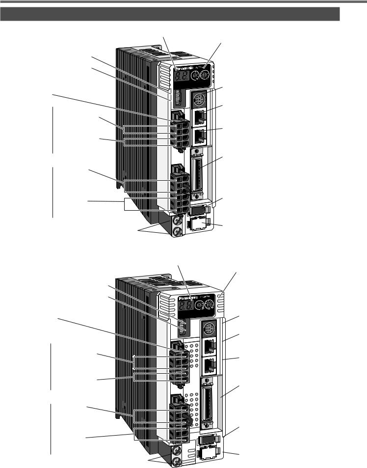
Driver
• A and B-frame |
Display LED (2-digit) |
ID address setup |
|
||
|
|
rotary switch (MSD, LSD) |
Velocity monitor check pin (SP) |
|
|
Torque monitor check pin (IM) |
|
|
Check pin (G : GND) |
|
|
Connector |
|
|
|
|
Main power |
|
|
|
Connector, CN X1 |
|
input terminals |
for power input |
|
(L1,L2) |
connection |
|
Control power |
04JFAT-SAXGF |
|
|
(JST) |
|
input terminals |
|
(L1C, L2C) |
|
|
|
|
|
|
Terminals |
|
|
|
Connector, CN X2 |
|
for external |
for motor |
|
regenerative resistor |
connection |
|
(RB1,RB2,RB3) |
06JFAT-SAXGF |
|
Terminals |
(JST) |
|
for motor connection |
|
|
(U,V,W) |
|
|
Screws for earth (x2) |
SP |
|
|
IM |
X4 |
|
G |
||
|
||
|
X3A |
|
|
X3B |
X5

 X6
X6
X7
Communication connector, CN X4
Connector, CN X4A
(For manufacturers' use only: Not for individual use)
Connector, CN X4B
(For manufacturers' use only: Not for individual use)
Connector, CN X5 for host connection
Connector, CN X6 for encoder connection
Connector, CN X7
for external scale connection
e.g.) : MADDT1207P (Single phase, 200V, 200W : A-frame)
• C and D-frame
Velocity monitor check pin (SP)
Torque monitor check pin (IM)
Check pin (G : GND)
Connector
|
|
Main power |
Connector, CN X1 |
|
input terminals |
for power input |
|
(L1,L2) |
connection |
|
Control power |
04JFAT-SAXGF |
|
|
(JST) |
|
input terminals |
|
(L1C, L2C) |
|
|
|
|
|
|
Terminals |
|
|
|
Connector, CN X2 |
|
for external |
for motor |
|
regenerative resistor |
connection |
|
(RB1,RB2,RB3) |
06JFAT-SAXGF |
|
Terminals |
(JST) |
|
for motor connection |
|
|
(U,V,W) |
|
|
Screws for earth (x2) |
Display LED (2-digit) |
ID address setup |
|
rotary switch (MSD, LSD) |
SP |
|
|
IM |
X4 |
|
G |
||
|
||
|
X3A |
|
|
X3B |
X5


 X6
X6
Communication connector, CN X4
Connector, CN X4A
(For manufacturers' use only: Not for individual use)
Connector, CN X4B
(For manufacturers' use only: Not for individual use)
Connector, CN X5 for host connection
Connector, CN X6 for encoder connection
X7 |
Connector, CN X7 |
|
for external scale connection |
e.g.) : MCDDT3520P (Single/3-phase, 200V, 750W : C-frame)
<Note>
X1 and X2 are attached in A to D-frame driver.
18

• E and F-frame
Check pin (G : GND)
Main power input terminals (L1,L2,L3)
Control power input terminals (r, t)
Terminals for external regenerative resistor
(P, B1, B2)
Terminals for motor connection (U,V,W)
[Before Using the Products]
Velocity monitor check pin (SP)
Torque monitor check pin (IM)
Display LED (2-digit)
ID address setup rotary switch (MSD, LSD)
SP |
|
IM |
X4 |
G |
|
|
X3A |
|
X3B |
|
X5 |
|
X6 |
|
X7 |
Communication connector, CN X4
Screw for cover M3
Connector, CN X4A
(For manufacturers' use only: Not for individual use)
Connector, CN X4B
(For manufacturers' use only: Not for individual use)
Connector, CN X5 for host connection
Connector, CN X6 for encoder connection
Connector, CN X7
for external scale connection
Screws for earth (x2) |
Terminal cover |
Screw for cover M3
e.g.) : MEDDT7364P (3-phase, 200V, 2.0kW : E-frame)
|
Check pin (G : GND) |
Velocity monitor check pin (SP) |
|
Torque monitor check pin (IM) |
|
|
|
|
Main power |
|
Display LED (2-digit) |
|
|
|
input terminals |
|
ID address setup |
(L1,L2,L3) |
|
rotary switch (MSD, LSD) |
Control power input terminals (r, t)
Terminals for external regenerative resistor
(P, B1, B2)
Terminals for motor connection (U,V,W)
Screws for earth (x2)
SP |
|
IM |
X4 |
G |
|
|
X3A |
|
X3B |
|
X5 |
|
X6 |
|
X7 |
Communication connector, CN X4
Screw for cover M3
Connector, CN X4A
(For manufacturers' use only: Not for individual use)
Connector, CN X4B
(For manufacturers' use only: Not for individual use)
Connector, CN X5 for host connection
Connector, CN X6 for encoder connection
Connector, CN X7
for external scale connection
Terminal cover
Screw for cover M3
Using Before Products the
e.g.) : MFDDTB3A2P (3-phase, 200V, 5.0kW : F-frame)
<Note>
For details of each model, refer to "Dimensions " (P.192 to 194) of Supplement.
19

Parts Description
Motor
• MSMD 50W to 750W
•MAMA 100W to 750W
•MQMA 100W to 400W
Encoder cable
Motor cable
Rotary encoder
Connector for brake cable
(Only applicable to the motor
Motor frame
with electromagnetic brake)
Flange |
Mounting holes (X4) |
e.g.) : Low inertia type (MSMD series, 50W)
•MSMA 1.0kW to 5.0kW
•MDMA 1.0kW to 5.0kW
• MHMA |
500W to 5.0kW |
• MFMA |
400W to 4.5kW |
• MGMA |
900W to 4.5kW |
Connector for motor and brake
Connector for encoder
Oil seal
Flange
Flange
Mounting holes (X4)
e.g.) : Middle inertia type (MDMA series, 1.0kW)
<Note>
For details of each model, refer to "Dimensions " (P.195 to P.209) of Supplement.
20
Console
Main Body
[Before Using the Products]
Using Before Products the
Connector
Console body
Display
(7-segment LED)
Cable
Touch panel
<Note>
Console is an option (Part No.: DV0P4420).
Display/Touch panel
Display LED (6-digit)
All of LED will flash when error occurs, and switch to error display
screen.
Display LED (in 2 digits)
Parameter No. is displayed at parameter setup mode. Point No. is
displayed at teaching mode.
SHIFT Button
Press this to shift the digit for data change.


 Button
Press these to change data or execute selected action of parameter. Numerical value increases by pressing ,  ,
,
decreases by pressing .
SET Button
Press this to shift each mode which is selected by mode switching button to EXECUTION display.
Mode Switching Button Press this to switch 7 kinds of mode.
1) |
Monitor mode |
5) |
Normal auto-gain tuning mode |
2) |
Teaching mode |
6) |
Auxiliary function mode |
|
• Target position settings established |
|
• Alarm clear |
|
by teaching |
|
• Absolute encoder clear |
|
• Test operation |
7) |
Copy mode |
3) |
Parameter setup mode |
|
• Copying of parameters from the driver to the console. |
4) |
EEPROM write mode |
|
• Copying of parameters from the console to the driver. |
The data for the parameters is set after the mode has been switched to the parameter setup mode. For details on operation, refer to the instruction manual provided with the console.
21

How to Install
Install the driver and the motor properly to avoid a breakdown or an accident.
Driver
Installation Place
1)Indoors, where the products are not subjected to rain or direct sun beams. The products are not waterproof.
2)Where the products are not subjected to corrosive atmospheres such as hydrogen sulfide, sulfurous acid, chlorine, ammonia, chloric gas, sulfuric gas, acid, alkaline and salt and so on, and are free from splash of inflammable gas, grinding oil, oil mist, iron powder or chips and etc.
3)Well-ventilated and low humidity and dust-free place.
4)Vibration-free place
Environmental Conditions
Item |
Condition |
Ambient temperature |
0˚C to 55˚C (free from freezing) |
|
|
Ambient humidity |
Less than 90% RH (free from condensation) |
|
|
Storage temperature |
–20˚C to 80˚C (free from freezing) |
|
|
Storage humidity |
Less than 90% RH (free from condensation) |
|
|
Vibration |
Lower than 5.9m/S2 (0.6G), 10 to 60Hz |
Altitude |
Lower than 1000m |
|
|
How to Install
1)Rack-mount type. Install in vertical position, and reserve enough space around the servo driver for ventilation. Base mount type (rear mount) is standard (A to D-frame)
2)Use the optional mounting bracket when you want to change the mounting face.
A to D-frame |
e.g.) In case of C-frame |
MADD |
|
MBDD |
Mounting bracket |
MCDD |
(optional parts) |
MDDD |
|
Fastening torque of earth screws (M4) to be 0.39 to 0.59N•m.
E and F-frame
Mounting bracket
22
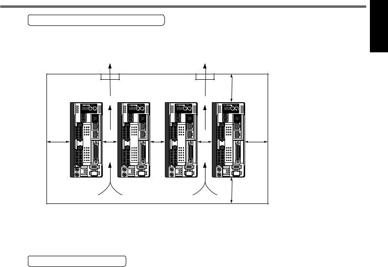
[Before Using the Products]
Mounting Direction and Spacing
•Reserve enough surrounding space for effective cooling.
•Install fans to provide uniform distribution of temperature in the control panel.
•Observe the environmental conditions of the control panel described in the next page.
Using Before Products the
|
|
|
|
|
|
|
|
|
|
100mm |
|
Fan |
|
|
|
Fan |
|
||||||
|
|
|
|
|
|
|
|
|
|
or more |
|
|
|
|
|
|
|
|
|
|
|
|
|
|
|
|
|
|
|
|
|
|
|
|
|
40mm |
or more |
10mm |
or |
more |
10mm |
or |
more |
10mm |
40mm |
|
or |
or more |
|
more |
||
|
100mm or more
<Note>
It is recommended to use the conductive paint when you make your own mounting bracket, or repaint after peeling off the paint on the machine for installing the products, in order to make noise countermeasure.
Caution on Installation
We have been making the best effort to ensure the highest quality, however, application of exceptionally large external noise disturbance and static electricity, or failure in input power, wiring and components may result in unexpected action. It is highly recommended that you make a fail-safe design and secure the safety in the operative range.
There might be a chance of smoke generation due to the failure of these products. Pay an extra attention when you apply these products in a clean room environment.
23
How to Install
Motor
Installation Place
Since the conditions of location affect a lot to the motor life, select a place which meets the conditions below.
1)Indoors, where the products are not subjected to rain or direct sun beam. The products are not waterproof.
2)Where the products are not subjected to corrosive atmospheres such as hydrogen sulfide, sulfurous acid, chlorine, ammonia, chloric gas, sulfuric gas, acid, alkaline and salt and so on, and are free from splash of inflammable gas, grinding oil, oil mist, iron powder or chips and etc.
3)Where the motor is free from grinding oil, oil mist, iron powder or chips.
4)Well-ventilated and humid and dust-free place, far apart from the heat source such as a furnace.
5)Easy-to-access place for inspection and cleaning.
6)Vibration-free place.
7)Avoid enclosed place. Motor may gets hot in those enclosure and shorten the motor life.
Environmental Conditions
|
Item |
|
Condition |
|
|
Ambient temperature |
0˚C to 40˚C (free from freezing) *1 |
||
|
|
|
||
|
Ambient humidity |
Less than 85% RH (free from condensation) |
||
|
Storage temperature |
–20˚C to 80˚C (free from freezing) *2 |
||
|
Storage humidity |
Less than 85% RH (free from condensation) |
||
|
Vibration |
|
Motor only |
Lower than 49m/s2 (5G) at running, 24.5m/s2 (2.5G) at stall |
|
Impact |
|
Motor only |
Lower than 98m/s2 (10G) |
|
|
|
|
IP65 (except rotating portion of output shaft and lead wire end) |
|
|
|
|
• These motors conform to the test conditions specified in EN |
Enclosure rating |
|
Motor only |
standards (EN60529, EN60034-5). Do not use these motors in |
|
|
|
|
|
application where water proof performance is required such as |
|
|
|
|
continuous wash-down operation. |
*1 Ambient temperature to be measured at 5cm away from the motor. *2 Permissible temperature for short duration such as transportation.
How to Install
You can mount the motor either horizontally or vertically as long as you observe the followings.
1)Horizontal mounting
•Mount the motor with cable outlet facing downward for water/oil countermeasure.
2)Vertical mounting
•Use the motor with oil seal (non-standard) when mounting the motor with gear reducer to prevent the reducer oil/grease from entering to the motor.
3)For mounting dimensions, refer to P.195 to 209 "Dimensions".
Oil/Water Protection
1)Don't submerge the motor cable to water or oil.
2)Install the motor with the cable outlet facing downward.
3)Avoid a place where the motor is subjected to oil or water.
4)Use the motor with an oil seal when used with the gear reducer, so that the oil may not enter to the motor through shaft.
Cable Motor 


Oil, water
24

[Before Using the Products]
Stress to Cables
1)Avoid a stress application to the cable outlet and connecting portion by bending or self-weight.
2)Especially in an application where the motor itself travels, fix the attached cable and contain the extension junction cable into the bearer so that the stress by bending can be minimized.
3)Take the cable bending radius as large as possible. (Minimum R20mm)
Using Before Products the
Permissible Load to Output Shaft
1) Design the mechanical system so that the applied radial load and/or thrust load to
the motor shaft at installation and at normal operation can meet the permissible Motor value specified to each model.
2)Pay an extra attention when you use a rigid coupling. (Excess bending load may  damage the shaft or deteriorate the bearing life.
3)Use a flexible coupling with high stiffness designed exclusively for servo application in order to make a radial thrust caused by micro misalignment smaller than the permissible value.
4)For permissible load of each model, refer to P.210, "List of Permissible Load to Output Shaft" of Supplement.
Notes on Installation
1)Do not apply direct impact to the shaft by hammer while attaching/detaching a coupling to and from the motor shaft.
(Or it may damage the encoder mounted on the other side of the shaft.)
2)Make a full alignment. (incomplete alignment may cause vibration and damage the bearing.)
3)If the motor shaft is not electrically grounded, it may cause electrolytic corrosion to the bearing depending on the condition of the machine and its mounting environment, and may result in the bearing noise. Check and verification by customer is required.
25

How to Install
Console
Installation Place
1)Indoors, where the products are not subjected to rain or direct sun beam. The products are not waterproof.
2)Where the products are not subjected to corrosive atmospheres such as hydrogen sulfide, sulfurous acid, chlorine, ammonia, chloric gas, sulfuric gas, acid, alkaline and salt and so on, and are free from splash of inflammable gas, grinding oil, oil mist, iron powder or chips and etc.
3)Well-ventilated and low humidity and dust-free place.
4)Easy-to-access place for inspection and cleaning
Environmental Conditions
Item |
Condition |
Ambient temperature |
0˚C to 55˚C (free from freezing) |
Ambient humidity |
Less than 90% RH (free from condensation) |
Storage temperature |
–20˚C to 80˚C (free from freezing) |
|
|
Storage humidity |
Less than 90% RH (free from condensation) |
|
|
Vibration |
Lower than 5.9m/s2 (0.6G), 10 to 60Hz |
Impact |
Conform to JISC0044 (Free fall test, 1m for 2 directions, 2 cycles) |
|
|
Altitude |
Lower than 1000m |
|
|
<Cautions>
•Do not give strong impact to the products.
•Do not drop the products.
•Do not pull the cables with excess force.
•Avoid the place near to the heat source such as a heater or a large winding resistor.
How to Connect
Connect to CN X4.
M
S
<Remarks>
•Connect the console connector securely to CN X4 connector of the driver
•Never pull the cable to plug in or plug out.
26

[Preparation] |
|
|
page |
System Configuration and Wiring ......................... |
28 |
Overall Wiring (Connecting Example of C-frame, 3-phase) ........ |
28 |
Overall Wiring (Connecting Example of E-frame) ....................... |
30 |
Driver and List of Applicable Peripheral Equipments .................. |
32 |
Wiring of the Main Circuit (A to D-frame) .................................... |
34 |
Wiring of the Main Circuit (E and F-frame).................................. |
35 |
Wiring to the Connector, CN X6 (Connection to Encoder) .......... |
38 |
Wiring to the Connector, CN X3 and 4 |
|
Wiring to the Connector, CN X7 (Connection to External Scale) ..... |
40 |
Wiring to the Connector, CN X5 (Connection to Host Controller)..... |
41 |
Wiring for Connector CN X5........................................................ |
42 |
Interface Circuit ........................................................................... |
43 |
List of Signal for Connector CN X5 ............................................. |
44 |
Setup with the Front Panel ..................................... |
48 |
Composition of Touch Panel and Display.................................... |
48 |
Initial Status of the Front Panel Display (7-Segment LED) ......... |
48 |
Output Signals (Analog) and Their Functions ............................. |
49 |
Built-in Holding Brake ............................................ |
50 |
Dynamic Brake ........................................................ |
52 |
27

System Configuration and Wiring
Overall Wiring (Connecting Example of C-frame, 3-phase)
• Wiring of the Main Circuit (see P.34, 35.)
(see P.32, 33 and 177.)
Circuit Breaker (NFB)
Use the circuit breaker matching capacity of the power source to protect the power lines.
(see P.177 , 178.)
Noise Filter (NF)
Prevents external noise from the power |
|
|
|
|
|
• Connection to |
||
|
|
|
|
|
||||
lines. And reduces an effect of the noise |
|
|
|
|
|
|||
|
|
|
|
|
the Connector, CN X1 |
|||
generated by the servo driver. |
|
|
|
|
|
|||
|
|
|
|
|
(connection to input power) |
|||
|
|
|
|
|
|
<Remarks> |
||
|
|
|
|
|
||||
(see P.32, 33.) |
|
|
|
|
|
|||
Magnetic Contactor (MC) |
|
|
|
|
|
Before turning the power |
||
Turns on/off the main power of the servo |
|
|
|
|
|
|||
|
|
|
|
|
supply on, check whether |
|||
driver. |
|
|
|
|
|
|||
|
|
|
|
|
the input voltage is correct. |
|||
Use a surge absorber together with this. |
|
|
|
|
|
|||
|
|
|
|
|
L1 (Pin-5) |
|||
|
|
|
|
|
||||
• Never start nor stop the servo motor |
|
|
|
|
|
|||
|
|
|
|
|
|
|||
with this Magnetic Contactor. |
|
|
|
|
|
L2 (Pin-4) |
||
|
|
|||||||
|
|
|
|
|
||||
|
|
|
|
|
|
L3 (Pin-3) |
||
(see P.189.) |
|
|
|
|
|
|
||
Reactor (L) |
|
|
|
|
|
|
|
|
Reduces harmonic current of the main |
|
|
|
|
|
|
L1C (Pin-2) |
|
|
|
|
|
|
|
|||
power. |
|
|
|
|
|
|
|
L2C (Pin-1) |
|
|
|
|
|
|
|
||
|
|
|
|
|
|
|
||
|
|
|
|
|
|
|
|
|
|
|
|
|
|
|
|
|
|
|
|
|
|
|
|
|
|
|
Pin RB1 (6-pin), RB2 (4-pin), and
RB3 (5-pin)
RB2 and RB3 to be kept shorted fornormal operation.
• When the capacity shortage of the regenerative resister is found, disconnect a shorting bar between RB2 and RB3, then connect the external regenerative resister between RB1 and RB2.
(Note that no regenerative resister is equipped in Frame A and B type.
Install an external regenerative resister on incombustible material, such as metal. Follow the same
wiring connection as the above.)
• When you connect an external regenerative resister, set up SV.Pr6C to 1 or 2.
•Connection to the Connector, CN X2
(connection to external components)
RB1 (Pin-6)
RB2 (Pin-4)
Handle lever
Use this for connector connection. Store this after connection for other occasions. (see page for connection.)
Regenerative resistor (optional) <Remarks>
•When you use an external regenerative resister, install an external protective apparatus, such as thermal fuse without fail.
•Thermal fuse and thermostat are built in to the regenerative resistor (Option). If the thermal fuse is activated, it will not resume.
28

[Preparation]
PC (to be supplied by customer)
Setup support software "PANATERM®" DV0P4460
X1
SP |
|
|
IM |
X4 |
|
G |
||
|
||
|
X3A |
|
|
X3B |
Console (option)
DV0P4420
•Wiring to Connector, CN X4 (option)
(Connection to PC or host controller)
•For manufacturers' use only, CN X3A and X3B
(Not for individual use)
|
|
• Wiring to Connector, CN X5 |
X2 |
X5 |
(Connection to host controller) |
|
||
|
|
|
• Wiring to Connector, CN X6 |
X6 |
(Connection to encoder) |
Short bar
Ground (earth)
U-phase (red)
V-phase (white)
W-phase (black)
Junction cable for motor
•Wiring to Connector, CN X2
(Connection to motor driving phase and ground)
Junction cable for brake
 : High voltage
X7
• Wiring to
Connector, CN X7
(Connection to external scale)
DC Power supply for brake DC24V
(to be supplied by customer)
Junction cable for encoder
Preparation
29
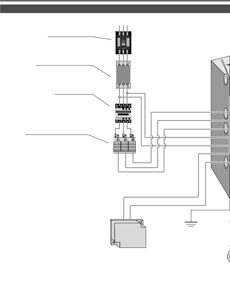
System Configuration and Wiring
Overall Wiring (Connecting Example of E-frame)
• Wiring of the Main Circuit (see P.36, 37.)
(see P.32, 33 and 177.)
Circuit Breaker (NFB)
Use the circuit breaker matching capacity of the power source to protect the power lines.
(see P.177 , 178.)
Noise Filter (NF)
Prevents external noise from the power lines. And reduces an effect of the noise generated by the servo driver.
(see P.32, 33.)
Magnetic Contactor (MC)
Turns on/off the main power of the servo driver.
Use a surge absorber together with this.
• Never start nor stop the servo motor with this Magnetic Contactor.
(see P.189.)
Reactor (L)
Reduces harmonic current of the main power.
•Connection with input power supply
<Remarks>
Before turning the power supply on, check whether the input voltage is correct.
L1
L2
L3
r
t
Pin P, B1 and B2...
B1 and B2 to be kept shorted for nor-
mal operation.
•When the capacity shortage of the regenerative resister is found, disconnect a short bar between B1 and B2, then connect the external regenerative resister between P and B2.
Install an external regenerative resister on incombustible material, such as metal. Follow the same wir-
ing connection as the above.
•When you connect an external regenerative resister, set up SV.Pr6C to 1 or 2.
• Connection to external components
P
B2
Ground (earth)
Regenerative resistor (optional) <Remarks>
When you use an external regenerative resister, install an external protective apparatus, such as thermal fuse without fail.
Thermal fuse and thermostat are built in to the regenerative resistor (Option). If the thermal fuse is activated, it will not resume.
30
 Loading...