


 Loading...
Technical Guide
Microwave Ovens with Inverters
Panasonic Services Company
National Training

Prepared by:
César Perdomo
Panasonic Services Company
National Training Department
Secaucus, NJ
 Warning
This service information is designed for experienced repair technicians only and is not designed for use by the general public. It does not contain warnings or cautions to advise non-technical individuals of potential dangers in attempting to service a product. Products powered by electricity should be serviced or repaired only by experienced professional technicians. Any attempt to service or repair the product or products dealt with in this service information by anyone else could result in serious injury or death.
Objective
The objective of this course is to provide the student with information about the latest technology used in Panasonic’s new line of microwave ovens.
Upon successful completion of this course, the student will learn the differences between the high voltage circuit used in most microwave ovens, and the Inverter technology used in this line of Panasonic microwave ovens.
The student will also have a better understanding of the new features and the function of the major components of the microwave oven.
Table Of Contents
Microwave ........................................................................................................... |
1 |
What are Microwaves?...................................................................................... |
1 |
How do microwaves cook?................................................................................ |
1 |
Inverter Technology............................................................................................ |
2 |
Difference Between MWO without Inverter and MWO with Inverter .................. |
2 |
Major components.............................................................................................. |
4 |
Magnetron ......................................................................................................... |
4 |
How to diagnose for an open filament or a shorted magnetron......................... |
4 |
Oven cavity ....................................................................................................... |
5 |
Turntable ........................................................................................................... |
5 |
Primary/secondary latch switches ..................................................................... |
6 |
Short switch....................................................................................................... |
6 |
Temperature Sensors........................................................................................ |
8 |
Steam Sensor.................................................................................................... |
9 |
How to check the steam-sensor function......................................................... |
10 |
Inverter Circuit ................................................................................................. |
11 |
Test and Measuring Procedures...................................................................... |
15 |
Procedure to check the Inverter using an Amp. Meter .................................... |
15 |
Measurement of microwave output ................................................................. |
16 |
Procedure for measuring microwave energy leakage ..................................... |
17 |
Safety Tips......................................................................................................... |
19 |
Safety tips for operation of microwave ovens.................................................. |
19 |
Safety tips for installation and maintenance of microwave ovens.................... |
19 |
Models line-up................................................................................................. |
20 |
Features............................................................................................................. |
21 |
Functions........................................................................................................... |
27 |
Understanding Ionizing & Non-Ionizing Radiation......................................... |
29 |
Troubleshooting................................................................................................ |
31 |
Inverter Circuit and Magnetron Troubleshooting ............................................. |
33 |
Glossary of Electronic & Microwave Oven Related Terms ........................... |
34 |
Microwave
What are Microwaves?
Microwaves, like visible light, are a part of the electromagnetic radiation spectrum. They are extremely high frequency radio waves. As the frequency of radiation increases, its wavelength decreases. The very high frequencies correspond to very short wavelengths; hence the name microwaves. Infrared radiation, ultraviolet light and X-rays are also electromagnetic radiations, but have even shorter wavelengths than microwaves.
Microwaves absorption and reflectivity are functions of the matter subjected to them. Metallic surfaces are good reflectors of microwaves. However, electrically non-conductive materials allow microwave to pass through them with very little absorption. All other materials that fall between metals and electrical isolators absorb microwave at different rates. Materials containing moisture, such as food and even people, absorb microwave energy. If energy is absorbed at a rate greater than the rate at which the material looses energy (rate of cooling), its temperature increases.
How do microwaves cook?
In microwave ovens, magnetrons are used to produce the microwaves. These microwaves have a frequency of 2,450 MHz, which is transmitted into the enclosed metal oven cavity. In the cavity, they are reflected by the oven walls and absorbed in food or drink placed in the oven.
Microwaves continuously reverse the polarity of the food molecules a tremendous number of times (2,450,000,000 times per second). This causes molecular agitation and thus friction, which produces heat and results in a rapid rise in temperature. Cooking time is usually much shorter than in a conventional oven.
The rate of heating depends on the type of food, its shape, volume, and mass.
The oven walls are not directly heated by microwaves, as they do not absorb microwave energy. However, the inside of the oven may feel warm due to the presence of the hot food and the heat generated by the electrical circuits.
1
Inverter Technology
Panasonic uses proprietary Inverter technology in most of its microwave ovens.
Difference Between Traditional and Inverter Microwave Ovens
Traditional microwave ovens
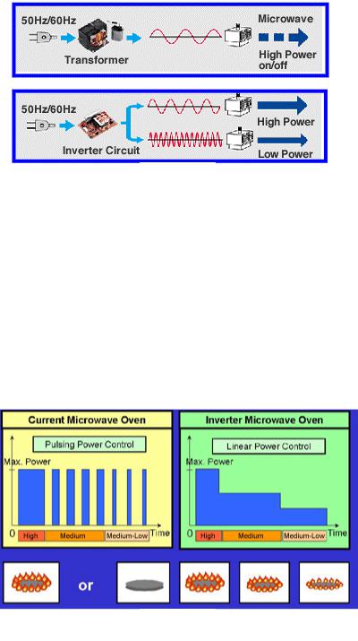
Conventional microwaves ovens use power transformers to increase the household line voltage (120 VAC at 60 Hz) to a level high enough to operate the magnetron. The magnetron generates the microwaves that cook the food. This technique has its drawbacks.
Operating at a low frequency of 60 Hz, the transformer is relatively inefficient:
•Power is lost (through heat dissipation) in converting the line voltage to the higher magnetron level.
•The transformer operates at a constant power (cooking level) that can only be changed by switching the power on or off repeatedly.
Inverter Technology
In inverter-equipped microwave ovens, the power transformer is replaced by a circuit board, which converts the 60Hz incoming line frequency to a variable rate of 20 KHz to 45 KHz. A relatively small transformer is then required to increase the voltage to the level required by a magnetron.
By varying the pulse width, the output power can be linearly controlled for more precise cooking and defrosting levels. The bulky power transformer is replaced by a small, lightweight circuit board; and, because less heat is dissipated, power efficiency is increased.
Conventional technology uses just a single power level, which is regulated by switching pulses. In contrast, inverter technology directly controls the power output. This constant soft penetration of microwave energy prevents the common problems of shrinkage, overcooking, and loss of nutrients. The result is even food temperature and textures throughout.
2
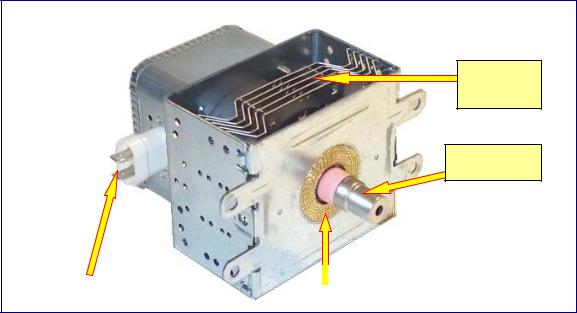
Power Level Comparison
Figure 1
Traditional microwaves send out a single level of power in small bursts to cook food at different speeds. For example, when set at 60% power, the microwave energy would be on 60% of the time and idle 40% of the time.
Inverter microwaves, however, give accurate, true multiple power levels. When you ask for 60% power, the oven delivers 60% power (e.g. they don’t just operate
60% of the time). This applies no matter what power level is selected. True power levels give you better cooking results and your food would have an even texture and temperature after cooking. The constant soft penetration of microwave energy into the center of the food helps prevent overcooking on edges and surfaces.
Difference Between Pulsing and Linear Power Control
Figure 2
3
Major components.
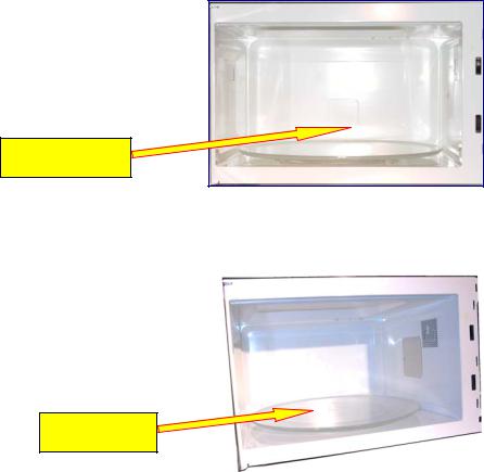
Magnetron
In a microwave oven, the magnetron is used to produce the high frequency required for cooking. The frequency of microwaves for general cooking is 2,450MHz.
Magnetron components
Cooling
Fins
Antenna
Filament Terminals |
|
Antenna Gasket |
|
|
|
Figure 3
How to diagnose for an open filament or a shorted magnetron
To check for open filament:
•Disconnect the filament leads.
•Measure the resistance across the filament terminals. The normal resistance is approximately 1 ohm or less.
To check for a shorted magnetron:
•Disconnect the filament leads.
•Measure the resistance between each filament terminal and the magnetron case. Normally it should read open.
Note:
Do not rely on continuity check alone to determine if a magnetron is defective. Normal continuity reading can be obtained from a magnetron that is defective.
4
Whenever you replace the magnetron, measure for radiation leakage before the outer panel is installed and after all necessary components are replaced or adjusted.
Warning:
Special care should be taken in measuring around the magnetron.
Avoid contact with any of the high voltage parts while conducting the radiation leakage test.
Oven cavity
The cavity is a multimode cavity resonator designed to resonate the microwaves emitted from the magnetron. Here is where the food is placed for cooking or heating.
The oven cavity is made with stainless steel, aluminum, or painted steel plate to reflect the microwaves.
Oven Cavity
Figure 4
Turntable
The microwaves come into the oven’s cavity from the side of the oven to ensure that the microwave field evenly covers the top, sides, and bottom of the food. The turntable then exposes all parts of the food to the field, for perfect results every time.
Turntable
Figure 5
5
Primary / secondary latch switches
These are safety switches, and their basic function is to interrupt the power supply to the magnetron when the door starts to open. They are open when the door is opened.
Switch position
Switch |
Door Opened |
Door Closed |
Primary |
Open |
Close |
Secondary |
Open |
Close |
Table 1
Short switch
This switch is used to prevent the operation of the microwave oven while the door is opened.
The short switch creates a short circuit to blow the line fuse and stop microwave oven’s operation if the door switches fail to open when the door is opened.
This switch is normally open when the door is closed.
Switches Location |
Primary Switch |
Side view of Microwave Oven |
Short Switch (Lower) |
Secondary Switch (Upper) |
Figure 6
Note: When the fuse is blown due to operation of the short switch, replace the primary switch, the short switch, the secondary switch, and the power relay.
6
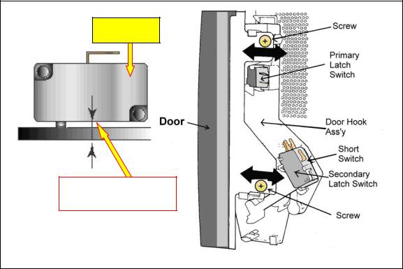
Adjustment of the primary latch switch, the secondary latch switch, and the short switch
1.Mount the primary latch switch, the secondary latch switch, and the short switch to the door hook assembly as shown in the figure 7.
NOTE: No specific individual adjustments during installation of the primary latch switch, secondary latch switch or short switch to the door hook are required.
2.When mounting the door hook assembly to the oven assembly, adjust the door hook assembly by moving it in the direction of the arrows in figure 7, so that the oven door will not have any play in it.
3.Check for play in the door by pulling the door assembly.
4.Make sure that the latch keys move smoothly after adjustment is completed. Tighten the screws holding the door hook assembly to the oven assembly.
5.Reconnect the short switch and check the continuity of the monitor circuit and all latch switches again by following the component test procedures.
Interlock switches
Switch
Actuator
The gap should be less than 0.7mm
Figure 7
7

Temperature Sensors
This microwave oven uses 2 different types of temperature sensors. One is a thermal cutout sensor located on top of the oven cavity, and the other is a thermistor, which is mounted on the side of the magnetron. See Figure 8.
The thermal cutout sensor is used to stop the flow of AC to the oven, if the cavity surface overheats for any reason.
The thermistor will shut the oven down and reset the display when the magnetron overheats and reaches a temperature of 257° F.
The cooking program can be re-started after the magnetron cools down. The value of this thermistor is 30K to 120K at 50°F ~ 86°F.
Temperature Sensors Location
Thermal cutoff
Thermistor
Figure 8
8
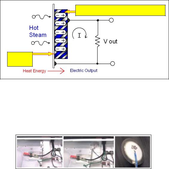
Steam Sensor
This sensor detects the presence of steam emitted by the food being heated and then, based on how long it took to reach the steam stage, it gauges how much longer it should cook, before shutting off.
The steam sensor works just like the effect called piezoelectricity. The piezoelectricity effect generates electricity when mechanical shock is applied to the general dielectrics material.
In the case of the steam sensor, this effect is called pyroelectricity, where electricity is generated when heat shock (hot steam) is applied to the general dielectrics material. See the figure below.
Principle of Steam Sensor
Dielectrics (Pyroelectricitic) Material |
Steam |
Sensor |
Figure 9
When the food is heated by the microwave oven, the food temperature gradually increases and steam is generated from the food. The steam sensor, which is located near the cooling fan, detects the steam from the food.
The fan keeps one side of the sensor cool and the other side, which has the element, receives and feels the hot steam from the oven cavity.
Steam Sensor Location
Figure 10
9
Loading...