


INSTRUCTION MANUAL
CO2 Incubator
MCO-5AC
45
Note:
1.No part of this manual may be reproduced in any form without the expressed written permission of SANYO.
2.The contents of this manual are subject to change without notice.
3.Please contact SANYO if any point in this manual is unclear or if there are any inaccuracies.
SANYO Electric Biomedical Co., Ltd. All rights reserved. Printed in Japan.
CONTENT
|
PRECAUTIONS FOR SAFE OPERATION |
P. 2 |
||||
|
CAUTIONS FOR USAGE |
P. 7 |
||||
|
Labels on the unit |
P. 9 |
||||
|
INCUBATOR COMPONENTS |
P.11 |
||||
|
Control panel and keypad |
P.13 |
||||
|
Remote alarm terminal |
P.14 |
||||
|
INSTALLATION |
|
||||
|
Installation site |
P.15 |
||||
|
Prevent contamination |
P.16 |
||||
|
Installation |
P.16 |
||||
|
BEFORE COMMENCING OPERATION |
|
||||
|
Sterilizing of chamber and attachments |
P.17 |
||||
|
Connection of CO2 gas cylinder |
P.18 |
||||
|
Automatic CO2 cylinder changeover |
P.19 |
||||
|
OPERATING INSTRUCTIONS |
|
||||
|
Set of chamber temperature and CO2 density |
P.20 |
||||
|
UV lamp |
P.21 |
||||
|
Change of setting of UV lamp ON period |
P.22 |
||||
|
Key lock function |
P.23 |
||||
|
Water level sensor |
P.24 |
||||
|
ALARMS & SAFETY FUNCTIONS |
P.25 |
||||
|
SETTING OF ALARM RESUME TIME |
P.26 |
||||
|
ROUTINE MAINTENANCE |
|
||||
|
Sterilizing of chamber and attachments |
P.27 |
||||
|
Removal of attachments |
P.28 |
||||
|
Filling the humidifying pan |
P.30 |
||||
|
CALIBRATION |
|
||||
|
Temperature calibration |
P.31 |
||||
|
CO2 calibration |
P.32 |
||||
|
TROUBLESHOOTING |
P.33 |
||||
|
ENVIRONMENTAL CONDITIONS |
P.34 |
||||
|
DISPOSAL OF UNIT |
P.34 |
||||
|
STACKED MODULE |
P.35 |
||||
|
SPECIFICATIONS |
P.37 |
||||
|
PERFORMANCE |
P.38 |
||||
|
SAFETY CHECK SHEET |
P.39 |
||||
1 |
|
|
46 |
|
|
|
|
|
|
|
|||
PRECAUTIONS FOR SAFE OPERATION
It is imperative that the user complies with this manual as it contains important safety advice.
Items and procedures are described so that you can use this unit correctly and safely. If the precautions advised are followed, this will prevent possible injury to the user and any other person.
Precautions are illustrated in the following way:
 WARNING
Failure to observe WARNING signs could result in a hazard to personnel possibly resulting in serious injury or death.
 CAUTION
Failure to observe CAUTION signs could result in injury to personnel and damage to the unit and associated property.
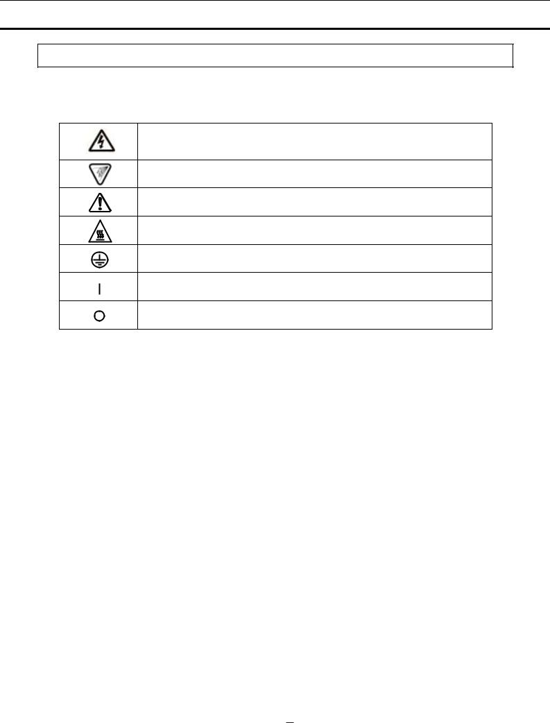
Symbol shows;
 this symbol means caution or warning.
 this symbol means an action is prohibited.
 this symbol means an instruction must be followed.
Be sure to keep this manual in a place accessible to users of this unit.
< Label on the unit >
This mark is labeled on the cover in which the electrical components of high voltage are enclosed to prevent the electric shock.
The cover should be removed by a qualified engineer or a service personnel only.
47 |
|
2 |
|

PRECAUTIONS FOR SAFE OPERATION
 WARNING
Do not use the unit outdoors. Current leakage or electric shock may result if the unit is exposed
to rain water.
Only qualified engineers or service personnel should install the unit. The installation by unqualified personnel may cause electric shock or fire.
Install the unit on a sturdy floor. If the floor is not strong enough or the installation site is not adequate, this may result in injury from the unit falling or tipping over.
Never install the unit in a humid place or a place where it is likely to be splashed by water.
Deterioration of the insulation may result which could cause current leakage or electric shock.
 Never splash water directly onto the unit as this may cause electric shock or short circuit.
 Use a dedicated power source as indicated on the rating label attached to the unit.
Remove dust from the power supply plug before inserting in a power source. A dusty plug or
improper insertion may cause a hazard.
Use a power supply outlet with ground (earth) to prevent electric shock. If the power supply outlet is not grounded (earthed), it will be necessary to install a ground by qualified engineers.
Never ground the unit through a gas pipe, water main, telephone line or lightning rod. Such
grounding may cause electric shock in the case of an incomplete circuit.
Check the gas type and ensure that it is fit for the purpose. Make sure that all pipes are connected correctly and are not liable to become disconnected. Ensure that the gas  pressure is set at the specified value. Improper connection of the gas pipe or use of incorrect gas pressure may result in leakage of CO2 gas. Elevated level of CO2 gas can be
hazardous to health and may lead to asphyxiation and risk of death.
 Never store volatile or flammable substances in this unit. This may cause explosion or fire.
Ventilate a room air occasionally when using CO2 gas for control. The gas density will increase in an enclosed small room and high level of gas density can be hazardous to health. In addition, avoid inhaling the chamber air directly when opening the door if CO2 gas is used.
Si l’appareil est utilisé dans un evdroit restreint, le niveau de la densité CO2 de l’air peut s’élever et peut être nocif aux humains. Évitez d’aspirer l’air provenant de l’intérieur de l’appareil quand vous ouverz la porte.
Do not insert metal objects such as a pin or a wire into any vent, gap or any outlet for inner air
circulation. This may cause electric shock or injury by accidental contact with moving parts.
3 |
|
48 |
|
PRECAUTIONS FOR SAFE OPERATION
 WARNING
As with any equipment that uses CO2 gas, there is a likelihood of oxygen depletion in the vicinity of the equipment. It is important that you assess the work site to ensure there is  suitable and sufficient ventilation. If restricted ventilation is suspected, then other methods of ensuring a safe environment must be considered. These may include atmosphere
monitoring and warning devices. Keep proper gas pressure to avoid gas leak.
Use this unit in a safe area if using poisonous, harmful or radioactive substances. Improper
use may be harmful to your health or the environment.
Disconnect the power supply to the unit prior to any repair or maintenance in order to prevent
electric shock or injury.
Never expose the eyes directly to UV light as UV light can cause permanent damage to eyes. Never remove cover when UV light is ON (when an optional UV system kit MCO-18UVS2 is installed).
 Hazardous UV light. Do not press door switch.
Never disassemble, repair, or modify the unit yourself. Any such work carried out by an unauthorized person may result in fire or injury due to a malfunction.
Disconnect the power supply plug if there is anything wrong with the unit. Continued 

 abnormal operation may cause electric shock or fire.
If the unit is to be stored unused in an unsupervised area for an extended period, ensure that children do not have access and that doors cannot be closed completely.
The disposal of the unit should be undertaken by appropriate personnel. Remove doors to
prevent accidents such as suffocation.
Prepare a safety check sheet when you request any repair or maintenance for the safety of service
personnel.
49 |
|
4 |
|
PRECAUTIONS FOR SAFE OPERATION
 CAUTION
Select a level and sturdy floor for installation. This precaution will prevent the unit from tipping.
Improper installation may result in water spillage or injury from the unit tipping over.
Connect the unit to a power source as indicated on the rating label attached to the unit.
Use of any other voltage or frequency other than that on the rating label may cause fire or electric
shock.
When removing the plug from the power supply outlet, grip the power supply plug, not the
cord. Pulling the cord may result in electric shock or fire by short circuit.
Never damage or break the power supply plug or cord. Do not use the supply plug if its cord is loose. This may cause fire or electric shock.
Do not touch any electrical parts such as the power supply plug or any switches with a wet hand. This may cause electric shock.
Do not put a container with water or heavy articles on the unit. It may cause injury if the  articles fall. Current leakage or electric shock may result form deterioration of insulation by spilled
water.
Do not climb onto the unit and do not put articles on the unit. This may cause injury by tipping or damage to the unit. When stacking the unit, follow the procedure shown on page 35.
Always hold the handle when closing the door. This will reduce the likelihood of a trapped
finger.
Do not damage the power supply cord. Stepping on the cord, or processing, pulling, twisting, or binding of cord may cause fire or electric shock by damaged cord.
Never lean or press on the glass or never hit the glass with sharp edge. Intentional force may cause injury if the glass breaks.
Do not lean on the door. This may cause injury, current leakage, or electric shock if the unit tips
over or door becomes detached.
 Always put on gloves at the time of maintenance. The corners of fixtures may cause injury.
|
|
|
|
|
|
|
|
|
|
|
Disconnect the power supply plug before moving the unit. Take care not to damage the power |
||||
|
|
|
|
|
|
|
|
|
|
|
cord. A damaged cord may cause electric shock or fire. |
||||
|
|
|
|
|
|
|
|
|
|
|
|||||
|
|
|
|
|
|
|
|
||||||||
|
|
|
|
|
|
|
|
|
|
|
Empty the humidifying pan completely before moving the unit. Spilled or splashed water may |
||||
|
|
|
|
|
|
|
|
|
|
|
cause current leakage or electric shock. |
||||
5 |
|
|
|
|
|
|
|
|
|
|
|
|
50 |
|
|
|
|
|
|||||||||||||

PRECAUTIONS FOR SAFE OPERATION
 CAUTION
 Be careful not to tip over the unit during movement to prevent damage or injury.
Disconnect the power plug when the unit is not used for long periods. The deteriorated insulation 

 may cause electric shock, current leakage or fire.
 Do not put the packing plastic bag within reach of children as suffocation may result
 Take care of the inside of the outer door. It may get hot.
Use the power supply cord enclosed with the unit. Use of an inferior power supply cord may
cause electric shock or fire.
51 |
|
6 |
|
CAUTIONS FOR USAGE
1. Install on a sturdy and level floor
Install the unit on a sturdy and level floor and take precaution for preventing tipping over. Inadequate installation may result in water leakage or injury from the unit falling or tipping over.
2. Install in a place not subject to direct sunlight and far from heat sources
Never install the unit outdoor, near windows, or in direct sunlight. And install the unit far from heat sources such as exhausted heat from other equipment. The installation in improper location may result in insufficient performance.
3. Ventilate a room air
Ventilate a room air occasionally when using CO2 gas for control. The gas density will increase in an enclosed small room and high level of gas density can be hazardous to health. In addition, avoid inhaling the chamber air directly when opening the door if CO2 gas is used.
4. Setting of 5oC higher than the ambient temperature
The chamber temperature must be at least 5oC higher than the ambient temperature. For example, the chamber temperature is set to 37oC, the ambient temperature must be less than 32oC. Ensure the ambient temperature is within the desired range.
Also, do not place the unit in the direct air flow from an air conditioning system. Cool air from an air conditioning system may cause condensation and lead to possible contamination.
5. Always keep the chamber clean
The condensation may be caused on the inside of the door by spilled water form humidifying pan or opening of outer door for long period. Wipe off the condensation completely with a sterile dry gauze. Especially when the culture medium is spilled, clean and disinfect the chamber immediately. Refer to page 27 “Routine maintenance” for details.
6. Fill the humidifying pan with sterile distilled water
Always use sterile distilled water to fill the pan. The RH PAN lamp on the control panel flashes when the water level is low. Refill the sterile distilled water to the pan when the RH PAN lamp blinks. Note that when low temperature water is poured, the chamber temperature drops significantly. Clean the pan once a month.
7. Always shut the inner door
Shut the inner door completely, and then shut the outer door. If the inner door is not closed completely, even if the outer door is closed, the unit will fail to exhibit its maximum performance.
8. Open/close the doors gently
Ensure you close the doors gently. Robust closing may cause spillage of medium, incomplete closing, or damage of gasket. Also, before opening the inner door, check that the UV light is OFF (when an optional UV system kit MCO-18UVS2 is installed).
7 |
|
52 |
|

CAUTIONS FOR USAGE
9. Use clean containers
The Petri dishes or bottles for culturing may cause contamination in the chamber. Clean the containers before storing them in the chamber.
10. Allow adequate space between the cultures
When storing cultures in the chamber, keep the Petri dishes or bottles containing the cultures sufficiently apart from each other to allow adequate air circulation. Inadequate space may result in uneven temperature distribution and CO2 concentration in the chamber.
11. Stored materials
Never place acid or alkaline materials or materials that release corrosive gas in the chamber. Such materials can cause failure resulting from discoloration or corrosion.
12. Alarm
Always investigate the cause and fix the alarm condition immediately when the alarm is activated. Refer to page 25 for alarm details.
13. Do not use CAL key
Do not use CAL key on the control panel in normal use. Pressing this key leads the calibration mode. Wrong key operation affects the basic performance. Never touch any other keys on the control panel in the event of pressing CAL key accidentally. After about 90 seconds, the unit returns to chamber temperature display mode automatically.
14. If not used
When the unit is not used, dispose of the water in the humidifying pan and completely remove any moisture in the chamber completely. Check that the chamber is completely dry before closing the doors.
15.Thermal conductivity CO2 sensor
It is not abnormal that the thermal conductivity CO2 sensor displays CO2 density higher than the actual density when the chamber humidity temporarily goes down. And take care of the level of humidifying water because the lack of water affects the CO2 density.
53 |
|
8 |
|
CAUTIONS FOR USAGE
Labels on the unit
Some warning and/or caution labels are attached on the unit. Following shows the description of such
labels.
This label is on the cover in which the electrical components of high voltage are enclosed to prevent the electric shock. The cover should be removed by a qualified engineer or a service personnel only.
This symbol means UV caution.
This symbol means attention or refer to document.
This symbol means hot surface.
This symbol means earth.
This symbol means power switch “ON”.
This symbol means power switch “OFF”.
9 |
|
54 |
|
CAUTIONS FOR USAGE
The cautions below are applicable when an optional UV system kit MCO-18UVS2 is installed.
1. Always use humidifying pan and pan cover
The humidifying pan and pan cover prevent the UV light from escaping. Make sure they are installed even if you do not need humidity.
2. Notice of recommended replacement of UV lamp
This unit is provided with a function to notify the recommendation of UV lamp replacement when the accumulated ON time of UV lamp is over about 1,000 hours. The blink of the UV indicator on the control panel recommends the replacement of UV lamp. For the replacement, contact Sanyo sales representative or agent.
E18 will be displayed on the temperature indicator when the UV lamp is burned out. Contact Sanyo sales representative or agent for the replacement.
3. Location of UV lamp
The UV lamp is located in the duct. Take care not to damage the lamp at the time of installation/removal of attachments or humidifying pan.
55 |
|
10 |
|

INCUBATOR COMPONENTS
1 |
5 |
11 |
6 |
7 (inside) |
21
2
When MCO-18UVS2 is installed
12 ,14 ,15(inside)
Changeable
9 8 18
|
|
13 |
3 |
|
4 |
8 |
18 |
|
|
|
|
|
Switch cover |
|
|
|
Connecting port for CO2 gas |
|
|
|
|
|
10 |
17 |
|
|
|
|
|
16 |
|
|
|
|
|
19 |
|
|
|
|
|
When MCO-18UVS2 |
|
|
|
is installed |
20 |
|
|
|
|
|
Rear right side |
|
Rear left side |
|
|
|
|
11 |
|
56 |
|
INCUBATOR COMPONENTS
1.Outer door: Sticks to frame with magnetic seal. Door heater is installed in the door panel. The door opening is reversible. Contact Sanyo representative or agent to change the door hinge from left to right or vice versa.
2.Inner door: Made of tempered glass, however avoid excessive impact on the glass.
3.Leveling foot: Screw type for adjusting the height. Adjust the foot so that the unit can be level.
4.Tray: Can be pulled toward you.
5.Side support: Right and left side supports can be removed for disinfection. See page 28 and 29.
6.Rear duct: Flow path for circulating air. Removable.
7.Fan (inside the rear duct): Made from polypropylene resin. Can be sterilized by an autoclave.
8.Sample air outlet: This also functions as an internal gas outlet. Use only a supplied cap(9).
9.Sample air outlet cap: Always attach this cap except at the time of using of sample air outlet.
10.Connecting port for CO2 gas pipe (rear side): When an optional component MCO-5GC (gas cylinder changeover accessory) is installed, both A and B are available. If MCO-5GC is not used, only A is available. Refer to page 18 for gas cylinder connection. Ensure that the gas pressure is set at 0.03MPaG (0.3kgf/cm2G, 4.3psiG). Refer to page 19 for automatic cylinder changeover.
11.Door switch: Detects the door opening/closing and stops the circulating fan and electromagnetic valve for CO2 when door is open. UV lamp is also deactivated by door opening (When an optional UV system kit MCO-18UVS2 is installed).
12.Humidifying pan: Use sterile distilled water to fill the pan.
13.Humidifying pan cover: Prevents UV light being exposed to the chamber. When filling the pan, lift the front side and take out the pan. See page 30 for details.
14.UV lamp (When an optional UV system kit MCO-18UVS2 is installed):
Sanyo UV lamp does not generate ozone. Never look at the UV light directly. For replacement,
contact Sanyo representative or agent.
15.Water level sensor for humidifying pan: Detects the water level in the humidifying pan. See page 24 for details.
16.Remote alarm terminal: Refer to page 14.
17.Access port: When not in use, cap with the rubber cap on both outside and inside.
18.Power switch: Main switch of the unit. Also functions as an over-current breaker. The switch is covered by a switch cover to prevent the accidental push. To turn on or off the switch, remove the switch cover by loosening the screw. See figure on the right.
19.Glow starter (When an optional UV system kit MCO-18UVS2 is installed): For UV lamp (model; FG-7P)
20.Removal Power supply cord
21.Handle: Outer door handle. When moving the handle from upper to a lower position remove it from original position first, then remove two cups and screws at the lower position and attach the handle there.
57 |
|
12 |
|
 Loading...