


HC-X920P
Panasonic HC-X920P, HC-X920PC, HC-X920EF, HC-X920EG, HC-X920EP Service Manual
...
© Panasonic Corporation 2013 Unauthorized copying and distribution is a violation of law.
ORDER NO. VM1301005CE
B27
High Definition Video Camera
Model No. HC-X920P
HC-X920PC
HC-X920EB
HC-X920EE
HC-X920EF
HC-X920EG
HC-X920EP
HC-X929EG
HC-X920MGC
HC-X920MGK
HC-X920MGN
HC-X910PU
HC-X910GC
Colour
(K)...........Black Type
(S)...........Silver Type (only HC-X929EG)

2
TABLE OF CONTENTS
PAG E PAG E
1 Safety Precautions -----------------------------------------------3
1.1. General Guidelines ----------------------------------------3
1.2. Leakage Current Cold Check ---------------------------3
1.3. Leakage Current Hot Check (See Figure. 1) --------3
1.4. How to Discharge the Capacitor on Flash
P.C.B.----------------------------------------------------------4
2Warning--------------------------------------------------------------5
2.1. Prevention of Electrostatic Discharge (ESD)
to Electrostatically Sensitive (ES) Devices ----------5
2.2. How to Recycle the Lithium Ion Battery (U.S.
Only)-----------------------------------------------------------5
2.3. Caution for AC Cord (For EB/GC) ---------------------6
2.4. How to Replace the Lithium Battery -------------------7
3 Service Navigation------------------------------------------------8
3.1. Introduction --------------------------------------------------8
3.2. General Description About Lead Free Solder
(PbF) ----------------------------------------------------------8
3.3. Important Notice 1:(Other than U.S.A. and
Canadian Market) ------------------------------------------8
3.4. How to Define the Model Suffix (NTSC or PAL
model)---------------------------------------------------------9
3.5. Formatting-------------------------------------------------- 10
3.6. Baking of replacement IC and defective P.C.B.
---------------------------------------------------------------- 11
4 Specifications ---------------------------------------------------- 12
4.1. For NTSC Areas------------------------------------------12
4.2. For PAL Areas -------------------------------------------- 17
5 Location of Controls and Components ------------------ 22
6 Service Mode ----------------------------------------------------- 26
6.1. Built-in Memory Self Check Execution (HCX920M only) ----------------------------------------------- 27
6.2. Lock Search History Indication ----------------------- 27
6.3. Power ON Self Check Result Display---------------28
6.4. Forced full flash emission ------------------------------ 28
6.5. Erasing the lock histories ------------------------------ 29
6.6. Camera data indications while the video
playback ---------------------------------------------------- 29
6.7. Adjustment function for the Service ----------------- 30
6.8. Restore the backed up adjustment data------------ 31
6.9. Touch Panel Calibration -------------------------------- 32
7 Service Fixture & Tools --------------------------------------- 33
7.1. When Replacing the Main P.C.B. -------------------- 33
7.2. Service Position ------------------------------------------ 33
8 Disassembly and Assembly Instructions--------------- 35
8.1. Disassembly Flow Chart for the Unit ---------------- 35
8.2. PCB Location---------------------------------------------- 36
8.3. Disassembly Procedure for the Unit ---------------- 37
9 Measurements and Adjustments -------------------------- 54
9.1. Electric Adjustment --------------------------------------54
10 Factory Setting--------------------------------------------------- 67
10.1. How To Turn On The Factory Settings? ------------ 67
10.2. What Is The Factory Settings? ----------------------- 68
11 Block Di agr am --------------------------------------------------- 69
11.1. Overall Block Diagram ----------------------------------69
11.2. System Control Circuit Block Diagram--------------70
11.3. Video/Audio Signal Process(1) Circuit Block
Diagram----------------------------------------------------- 71
11.4. Video/Audio Signal Process(2) Circuit Block
Diagram ---------------------------------------------------- 72
11.5. Camera Circuit Block Diagram ----------------------- 73
11.6. Lens Drive Circuit Block Diagram ------------------- 74
11.7. Power Supply Circuit Block Diagram --------------- 75
12 Wiring Connection Diagram -------------------------------- 76
12.1. Interconnection Diagram------------------------------- 76
3
1 Safety Precautions
1.1. General Guidelines
1. IMPORTANT SAFETY NOTICE
There are special components used in this equipment
which are important for safety. These parts are marked by
in the Schematic Diagrams, Circuit Board Layout,
Exploded Views and Replacement Parts List. It is essential that these critical parts should be replaced with manufacturer’s specified parts to prevent X-RADIATION,
shock, fire, or other hazards. Do not modify the original
design without permission of manufacturer.
2. An Isolation Transformer should always be used during
the servicing of AC Adaptor whose chassis is not isolated
from the AC power line. Use a transformer of adequate
power rating as this protects the technician from accidents resulting in personal injury from electrical shocks. It
will also protect AC Adaptor from being damaged by accidental shorting that may occur during servicing.
3. When servicing, observe the original lead dress. If a short
circuit is found, replace all parts which have been overheated or damaged by the short circuit.
4. After servicing, see to it that all the protective devices
such as insulation barriers, insulation papers shields are
properly installed.
5. After servicing, make the following leakage current
checks to prevent the customer from being exposed to
shock hazards.
1.2. Leakage Current Cold Check
1. Unplug the AC cord and connect a jumper between the
two prongs on the plug.
2. Measure the resistance value, with an ohmmeter,
between the jumpered AC plug and each exposed metallic cabinet part on the equipment such as screwheads,
connectors, control shafts, etc. When the exposed metallic part has a return path to the chassis, the reading
should be between 1 MΩ and 5.2 MΩ. When the exposed
metal does not have a return path to the chassis, the
reading must be infinity.
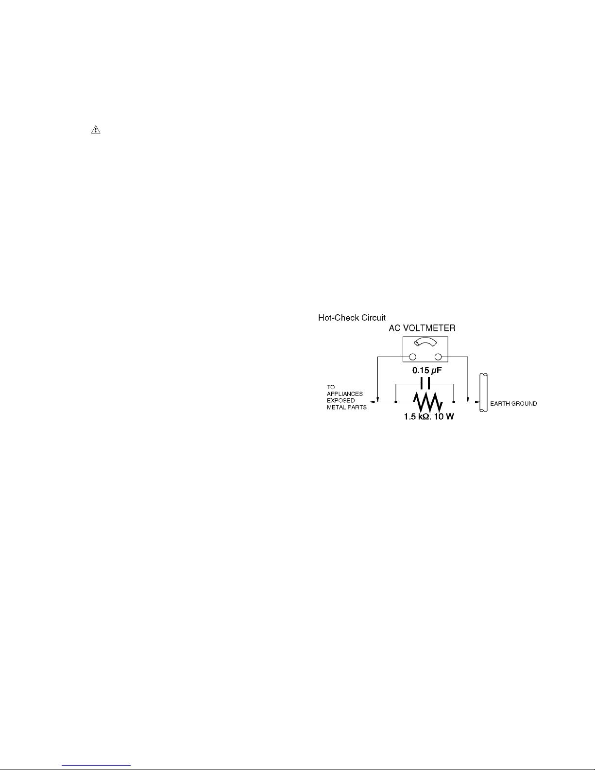
1.3. Leakage Current Hot Check
(See Figure. 1)
1. Plug the AC cord directly into the AC outlet. Do not use
an isolation transformer for this check.
2. Connect a 1.5 kΩ, 10 W resistor, in parallel with a 0.15 μF
capacitor, between each exposed metallic part on the set
and a good earth ground, as shown in Figure. 1.
3. Use an AC voltmeter, with 1 kΩ/V or more sensitivity, to
measure the potential across the resistor.
4. Check each exposed metallic part, and measure the voltage at each point.
5. Reverse the AC plug in the AC outlet and repeat each of
the above measurements.
6. The potential at any point should not exceed 0.75 V RMS.
A leakage current tester (Simpson Model 229 or equivalent) may be used to make the hot checks, leakage current must not exceed 1/2 mA. In case a measurement is
outside of the limits specified, there is a possibility of a
shock hazard, and the equipment should be repaired and
rechecked before it is returned to the customer.
Figure. 1
4
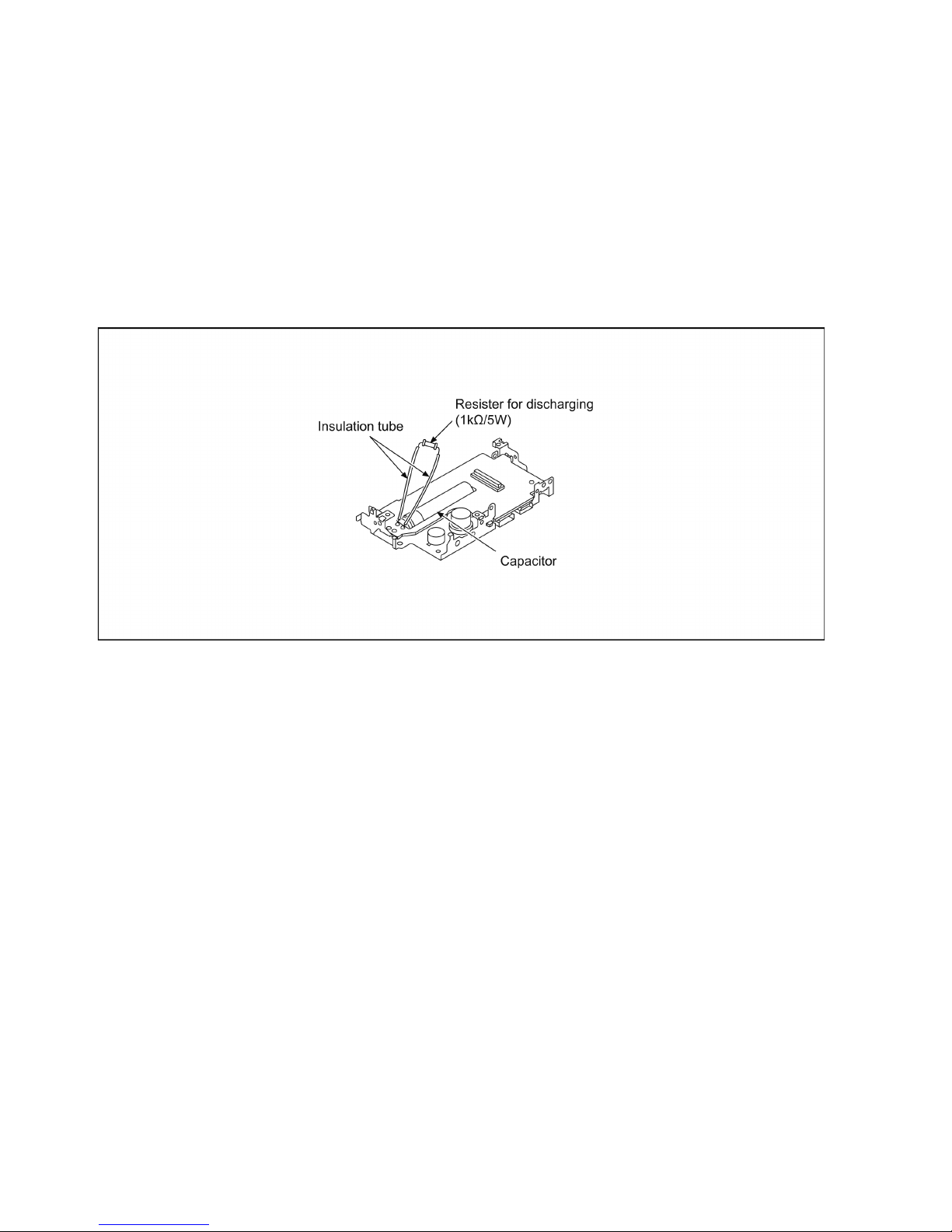
1.4. How to Discharge the Capacitor on Flash P.C.B.
CAUTION:
1. Be sure to discharge the capacitor on FLASH P.C.B..
2. Be careful of the high voltage circuit on FLASH P.C.B. when servicing.
Before disassembling, perform “6.4. Forced full flash emission” for discharging capacitor.
The capacitor also can be discharged according to the following procedures.
[Discharging Procedure]
1. Refer to the disassemble procedure and Remove the necessary parts/unit.
2. Put the insulation tube onto the lead part of Resistor (ERG5SJ102:1kΩ /5W).
(an equivalent type of resistor may be used.)
3. Put the resistor between both terminals of capacitor on FLASH P.C.B. for approx. 5 seconds.
4. After discharging confirm that the capacitor voltage is lower than 10V using a voltmeter.
Fig. F1
5
2Warning
2.1. Prevention of Electrostatic Discharge (ESD) to Electrostatically
Sensitive (ES) Devices
Some semiconductor (solid state) devices can be damaged easily by static electricity. Such components commonly are called Electrostatically Sensitive (ES) Devices. Examples of typical ES devices are integrated circuits and some field-effect transistors and
semiconductor "chip" components. The following techniques should be used to help reduce the incidence of component damage
caused by electrostatic discharge (ESD).
1. Immediately before handling any semiconductor component or semiconductor-equipped assembly, drain off any ESD on your
body by touching a known earth ground. Alternatively, obtain and wear a commercially available discharging ESD wrist strap,
which should be removed for potential shock reasons prior to applying power to the unit under test.
2. After removing an electrical assembly equipped with ES devices, place the assembly on a conductive surface such as aluminum foil, to prevent electrostatic charge buildup or exposure of the assembly.
3. Use only a grounded-tip soldering iron to solder or unsolder ES devices.
4. Use only an antistatic solder removal device. Some solder removal devices not classified as “antistatic (ESD protected)” can
generate electrical charge sufficient to damage ES devices.
5. Do not use freon-propelled chemicals. These can generate electrical charges sufficient to damage ES devices.
6. Do not remove a replacement ES device from its protective package until immediately before you are ready to install it. (Most
replacement ES devices are packaged with leads electrically shorted together by conductive foam, aluminum foil or comparable conductive material).
7. Immediately before removing the protective material from the leads of a replacement ES device, touch the protective material
to the chassis or circuit assembly into which the device will be installed.
CAUTION :
Be sure no power is applied to the chassis or circuit, and observe all other safety precautions.
8. Minimize bodily motions when handling unpackaged replacement ES devices. (Otherwise harmless motion such as the
brushing together of your clothes fabric or the lifting of your foot from a carpeted floor can generate static electricity (ESD) sufficient to damage an ES device).
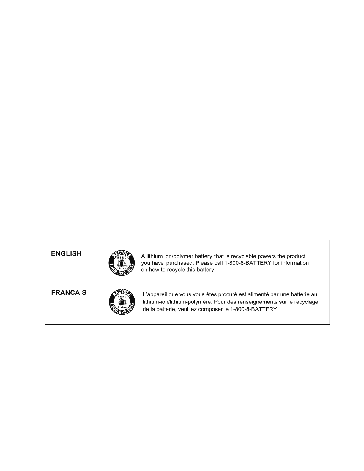
2.2. How to Recycle the Lithium Ion Battery (U.S. Only)
6
2.3. Caution for AC Cord
(For EB/GC)
2.3.1. Information for Your Safety
IMPORTANT
Your attention is drawn to the fact that recording of prerecorded tapes or discs or other published or broadcast
material may infringe copyright laws.
WARNING
To reduce the risk of fire or shock hazard, do not expose
this equipment to rain or moisture.
CAUTION
To reduce the risk of fire or shock hazard and annoying
interference, use the recommended accessories only.
FOR YOUR SAFETY
DO NOT REMOVE THE OUTER COVER
To prevent electric shock, do not remove the cover. No user
serviceable parts inside. Refer servicing to qualified service
personnel.
2.3.2. Caution for AC Mains Lead
For your safety, please read the following text carefully.
This appliance is supplied with a moulded three-pin mains plug
for your safety and convenience.
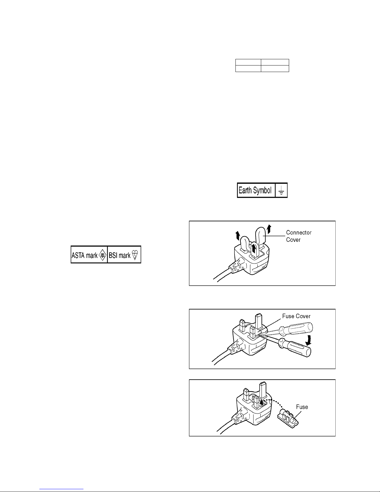
A 5-ampere fuse is fitted in this plug.
Should the fuse need to be replaced please ensure that the
replacement fuse has a rating of 5 amperes and it is approved
by ASTA or BSI to BS1362
Check for the ASTA mark or the BSI mark on the body of the
fuse.
If the plug contains a removable fuse cover you must ensure
that it is refitted when the fuse is replaced.
If you lose the fuse cover, the plug must not be used until a
replacement cover is obtained.
A replacement fuse cover can be purchased from your local
Panasonic Dealer.
If the fitted moulded plug is unsuitable for the socket outlet in
your home then the fuse should be removed and the plug cut
off and disposed of safety.
There is a danger of severe electrical shock if the cut off plug is
inserted into any 13-ampere socket.
If a new plug is to be fitted please observe the wiring code as
shown below.
If in any doubt, please consult a qualified electrician.
2.3.2.1. Important
The wires in this mains lead are coloured in accordance with
the following code:
As the colours of the wires in the mains lead of this appliance
may not correspond with the coloured markings identifying the
terminals in your plug, proceed as follows:
The wire which is coloured BLUE must be connected to the terminal in the plug which is marked with the letter N or coloured
BLACK.
The wire which is coloured BROWN must be connected to the
terminal in the plug which is marked with the letter L or coloured
RED.
Under no circumstances should either of these wires be connected to the earth terminal of the three pin plug, marked with
the letter E or the Earth Symbol.
2.3.2.2. Before Use
Remove the Connector Cover as follows.
2.3.2.3. How to Replace the Fuse
1. Remove the Fuse Cover with a screwdriver.
2. Replace the fuse and attach the Fuse cover.
Blue Neutral
Brown Live
7
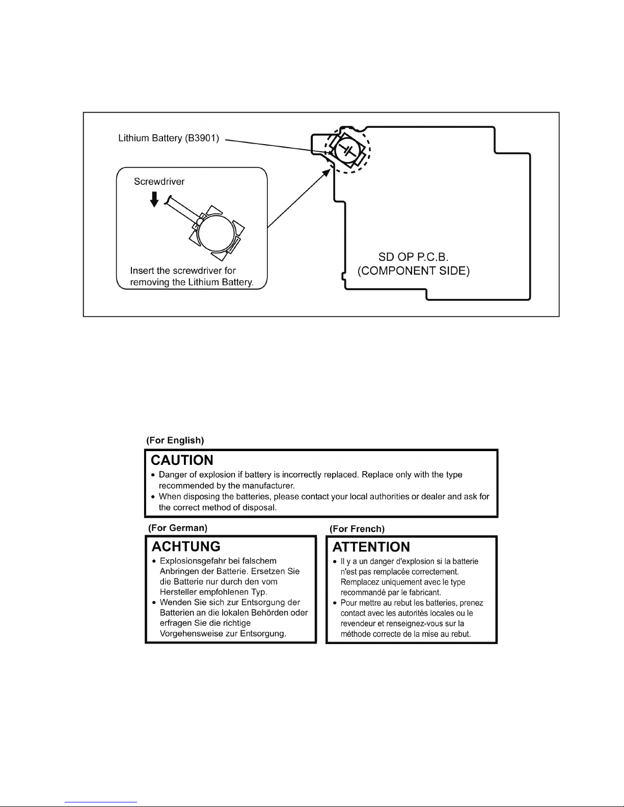
2.4. How to Replace the Lithium Battery
2.4.1. Replacement Procedure
1. Remove the SD OP P.C.B.. (Refer to Disassembly Procedures.)
2. Remove the Lithium battery (Ref. No. “B3901” at component side of SD OP P.C.B.) and then replace it into new one.
NOTE:
This Lithium battery is a critical component.
(Type No.: ML-614 Manufactured by Energy Company, Panasonic Corporation)
It must never be subjected to excessive heat or discharge.
It must therefore only be fitted in requirement designed specifically for its use.
Replacement batteries must be of same type and manufacture.
They must be fitted in the same manner and location as the original battery, with the correct polarity contacts observed.
Do not attempt to re-charge the old battery or re-use it for any other purpose.
It should be disposed of in waste products destined for burial rather than incineration.
NOTE:
Above caution is applicable for a battery pack which is for HC-X920/X929/X920M/X910 series, as well.
1. Battery Pack for this model.
8
3 Service Navigation
3.1. Introduction
This service manual contains technical information, which allow service personnel’s to understand and service this model.
Please place orders using the parts list and not the drawing reference numbers.
If the circuit is changed or modified, the information will be followed by service manual to be controlled with original service manual.
3.2. General Description About Lead Free Solder (PbF)
The lead free solder has been used in the mounting process of all electrical components on the printed circuit boards used for this
equipment in considering the globally environmental conservation.
The normal solder is the alloy of tin (Sn) and lead (Pb). On the other hand, the lead free solder is the alloy mainly consists of tin
(Sn), silver (Ag) and Copper (Cu), and the melting point of the lead free solder is higher approx.30°C (86°F) more than that of the
normal solder.
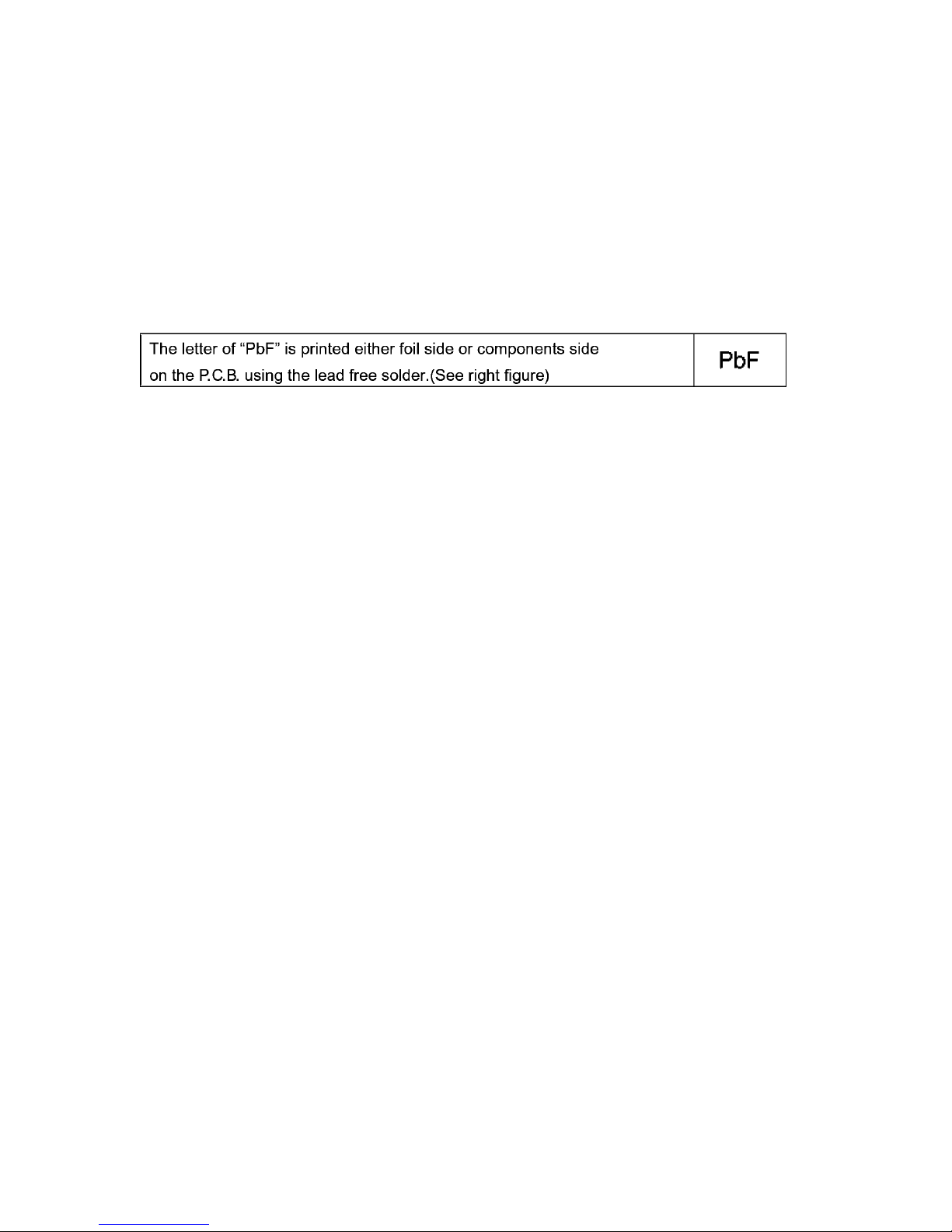
Distinction of P.C.B. Lead Free Solder being used
Service caution for repair work using Lead Free Solder (PbF)
• The lead free solder has to be used when repairing the equipment for which the lead free solder is used.
(Definition: The letter of “PbF” is printed on the P.C.B. using the lead free solder.)
• To put lead free solder, it should be well molten and mixed with the original lead free solder.
• Remove the remaining lead free solder on the P.C.B. cleanly for soldering of the new IC.
• Since the melting point of the lead free solder is higher than that of the normal lead solder, it takes the longer time to melt the
lead free solder.
• Use the soldering iron (more than 70W) equipped with the temperature control after setting the temperature at 350±30°C
(662±86°F).
Recommended Lead Free Solder (Service Parts Route.)
• The following 3 types of lead free solder are available through the service parts route.
RFKZ03D01KS-----------(0.3mm 100g Reel)
RFKZ06D01KS-----------(0.6mm 100g Reel)
RFKZ10D01KS-----------(1.0mm 100g Reel)
Note
* Ingredient: tin (Sn) 96.5%, silver (Ag) 3.0%, Copper (Cu) 0.5%, Cobalt (Co) / Germanium (Ge) 0.1 to 0.3%
3.3. Important Notice 1:(Other than U.S.A. and Canadian Market)
1. The service manual does not contain the following information, because of the impossibility of servicing at component level
without concerned equipment/facilities.
a. Schematic diagram, Block Diagram and P.C.B. layout of MAIN P.C.B..
b. Parts list for individual parts for MAIN P.C.B..
When a part replacement is required for repairing MAIN P.C.B., replace as an assembled parts. (Main P.C.B.)
2. The following category is /are recycle module part. Please send it/them to Central Repair Center.
- MAIN P.C.B. (VEP03J77C): HC-X920P/PC/EB/EE/EF/EG/EP,HC-X929EG
- MAIN P.C.B. (VEP03J77D): HC-X910PU/GC
- MAIN P.C.B. (VEP03J77B): HC-X920MGC/MGK/MGN
9
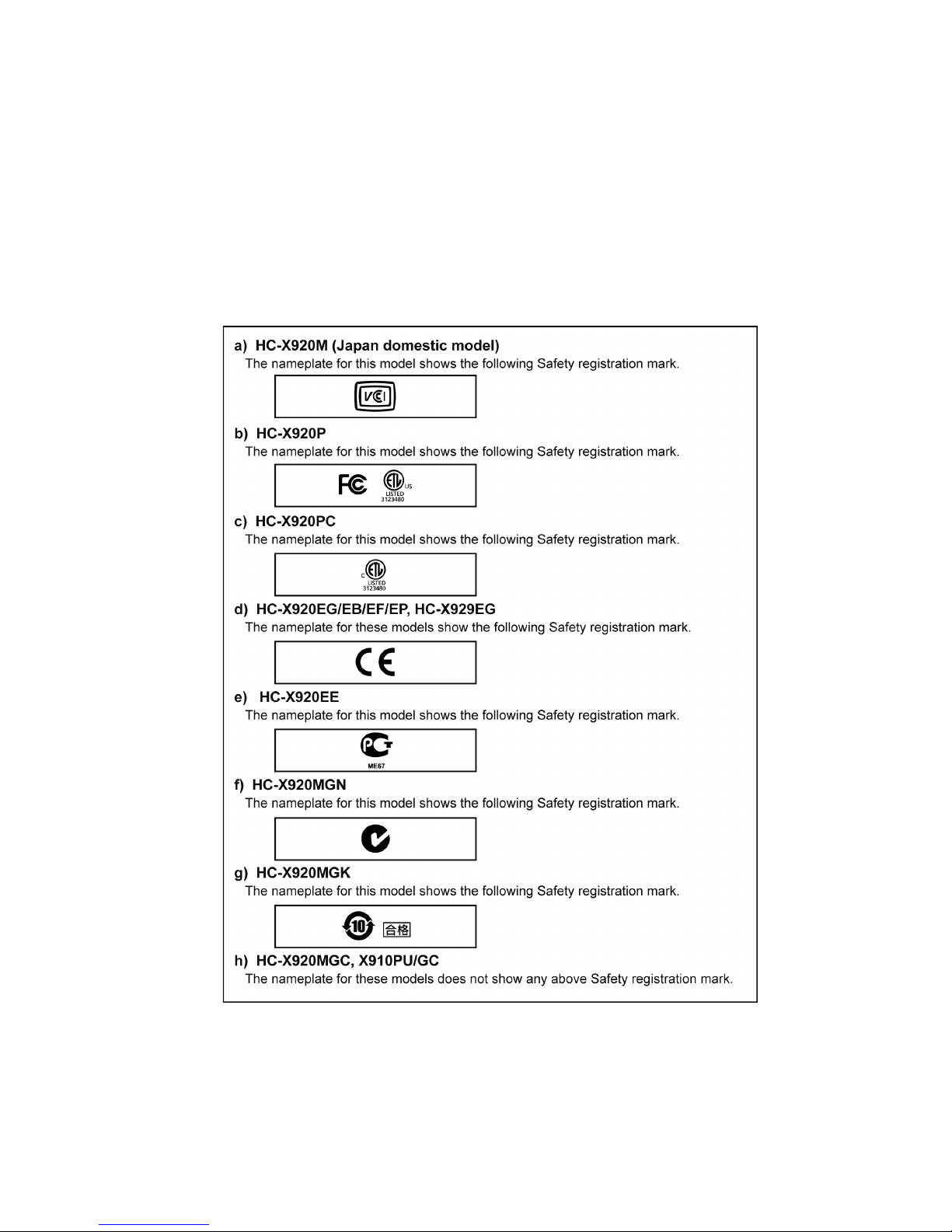
3.4. How to Define the Model Suffix (NTSC or PAL model)
There are eight kinds of HC-X920/X929/X920M/X910.
• a) HC-X920M (Japan domestic model)
• b) HC-X920P
• c) HC-X920PC
• d) HC-X920EG/EB/EF/EP, X929EG
• e) HC-X920EE
• f) HC-X920MGN
• g) HC-X920MGK
• h) HC-X920MGC, X910PU/GC
What is the difference is that the “INITIAL SETTING” data which is stored in Flash ROM mounted on Main P.C.B..
3.4.1. Defining methods:
To define the model suffix to be serviced, refer to the rating label and caution label which are putted on the Unit.
NOTE:
After replacing the MAIN P.C.B., be sure to achieve adjustment.
10
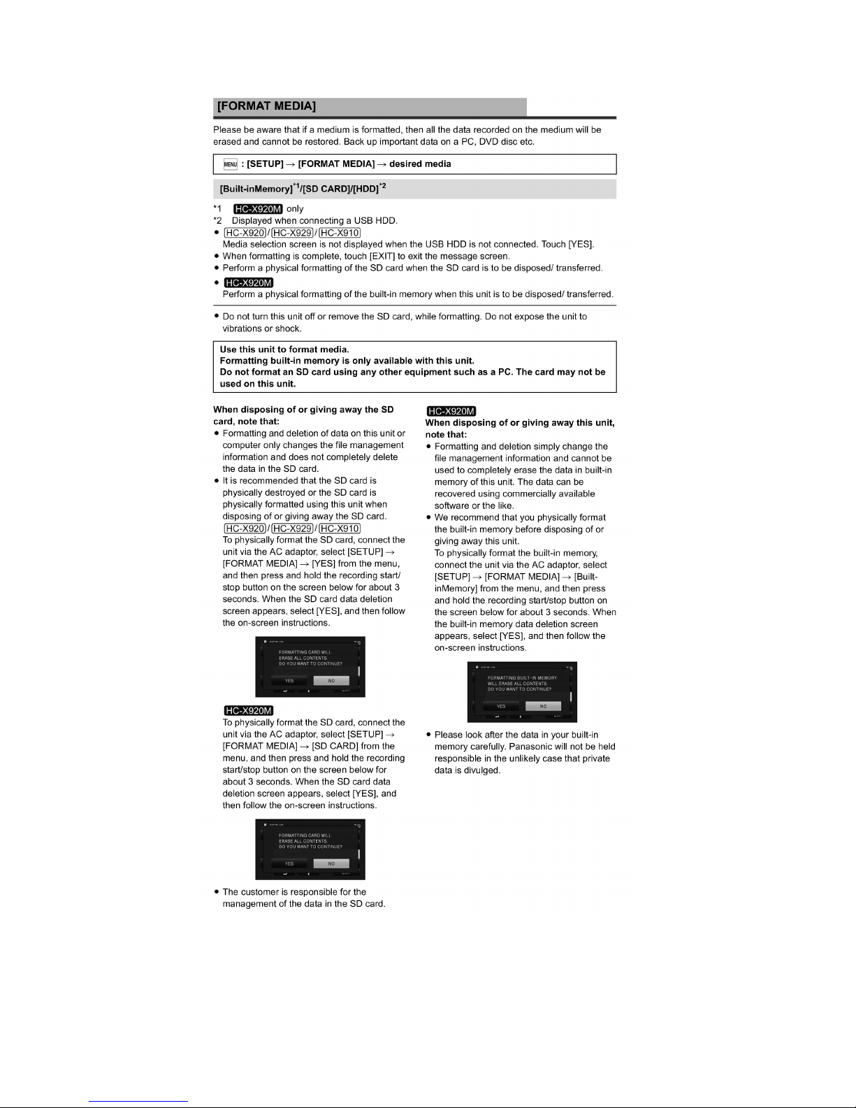
3.5. Formatting
11
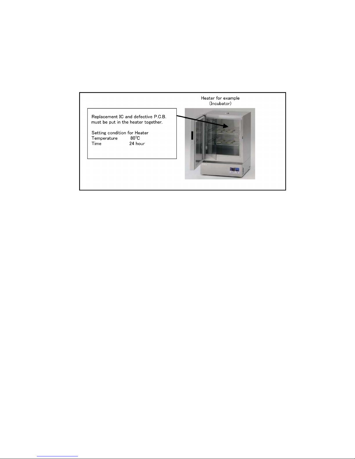
3.6. Baking of replacement IC and defective P.C.B.
When replacing the CSP/BGA/QFN type IC mounted on the P.C.B., the problem of IC crack or foil pattern breaking in the P.C.B.
might sometimes occur by rapid heating.
In order to improve the success rate of IC replacement for repair, it would be required to work out baking of replacement
IC and defective P.C.B. before replacing IC.
Please refer the way of baking as follows.
Replacement IC and defective P.C.B. must be put in the heater together.
• Baking temperature and time (Hour)
80°C / 24 hour
12
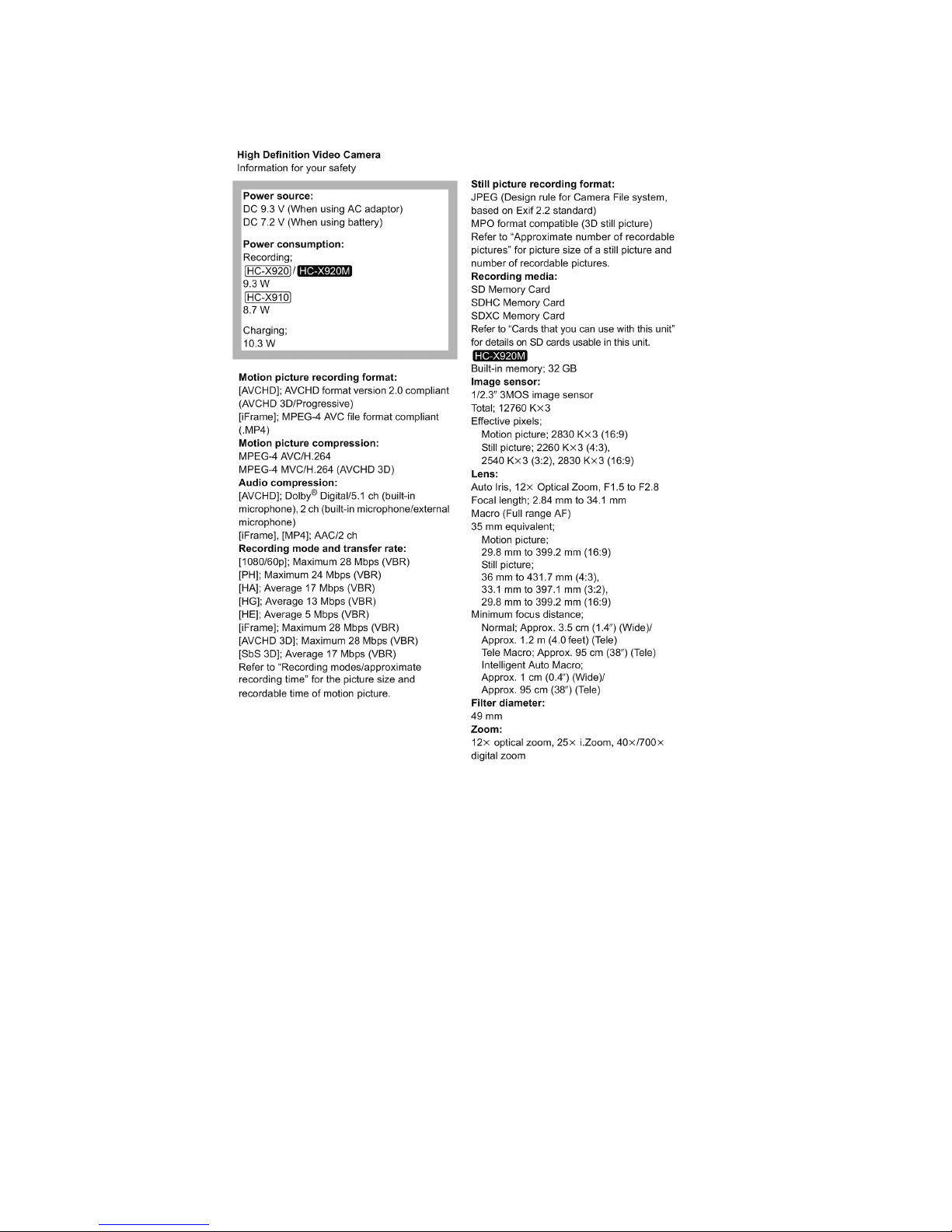
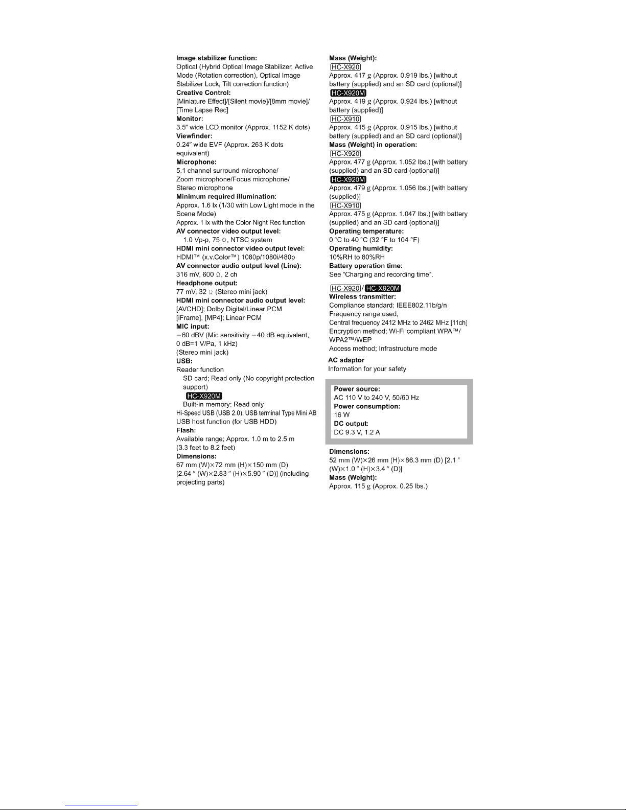
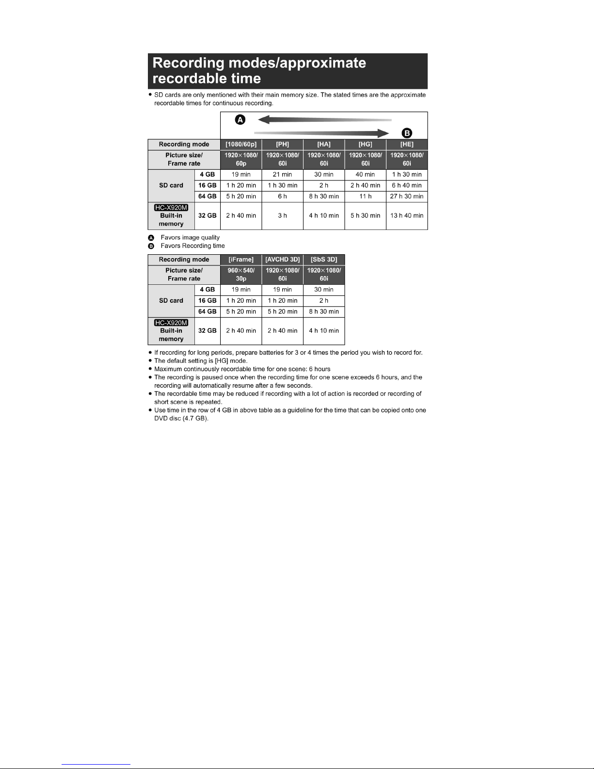
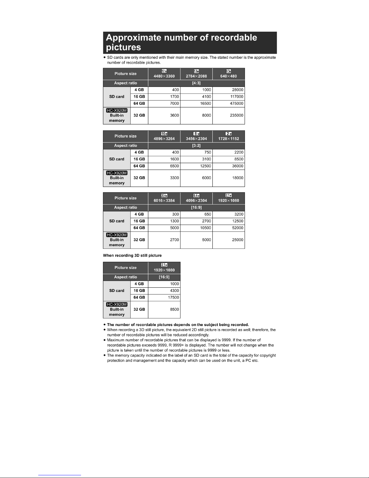
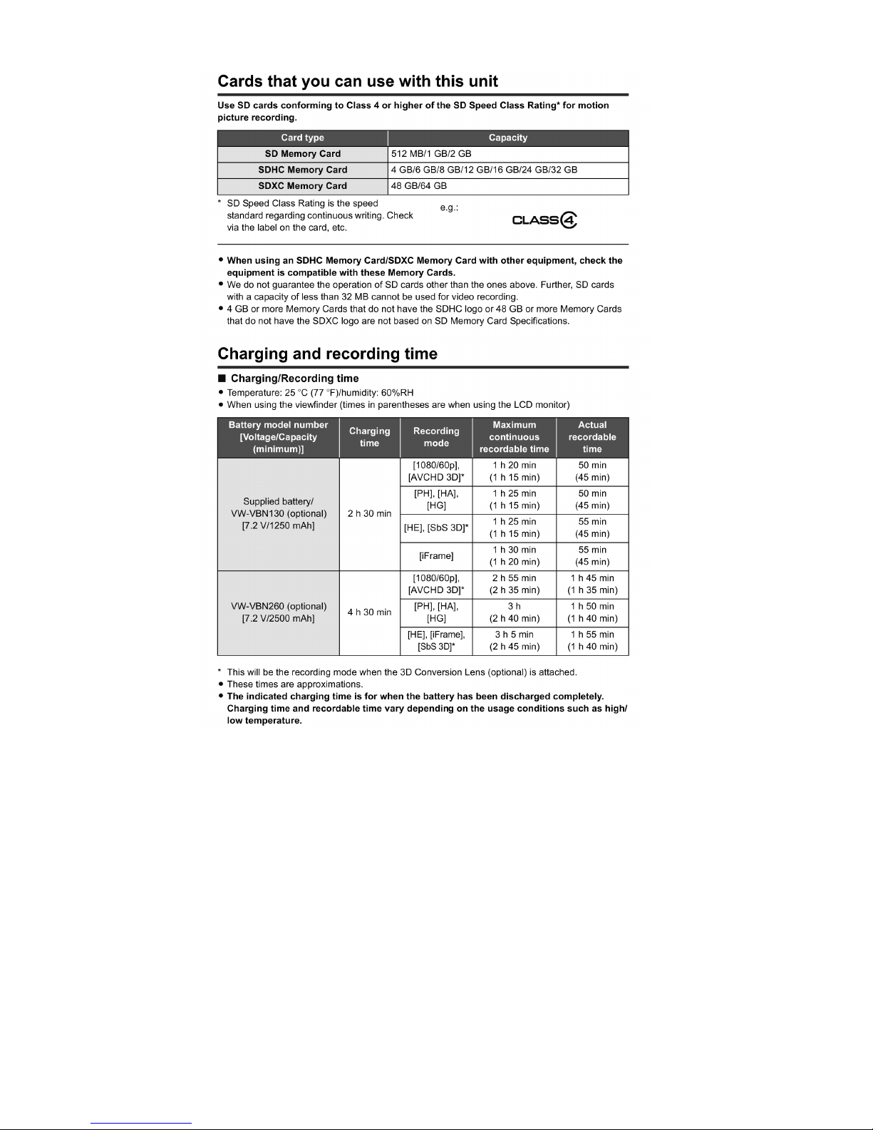
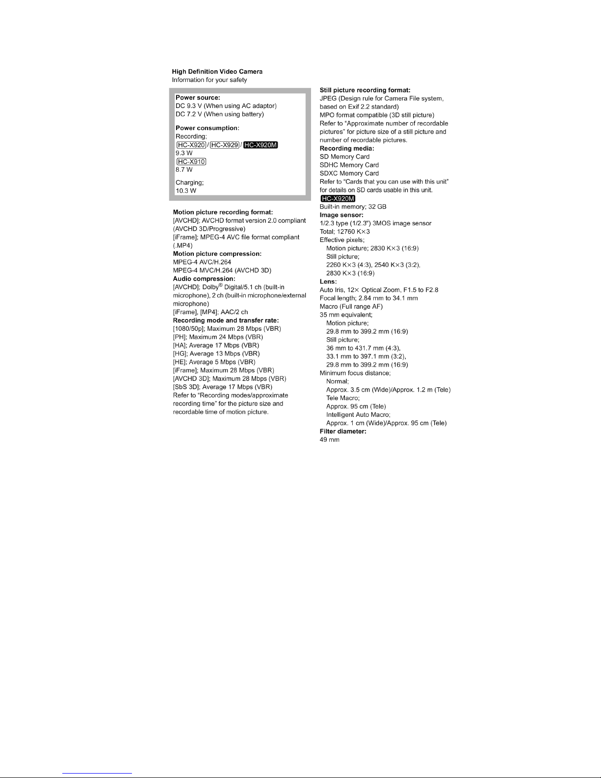
4 Specifications
4.1. For NTSC Areas
13
14
15
16
17
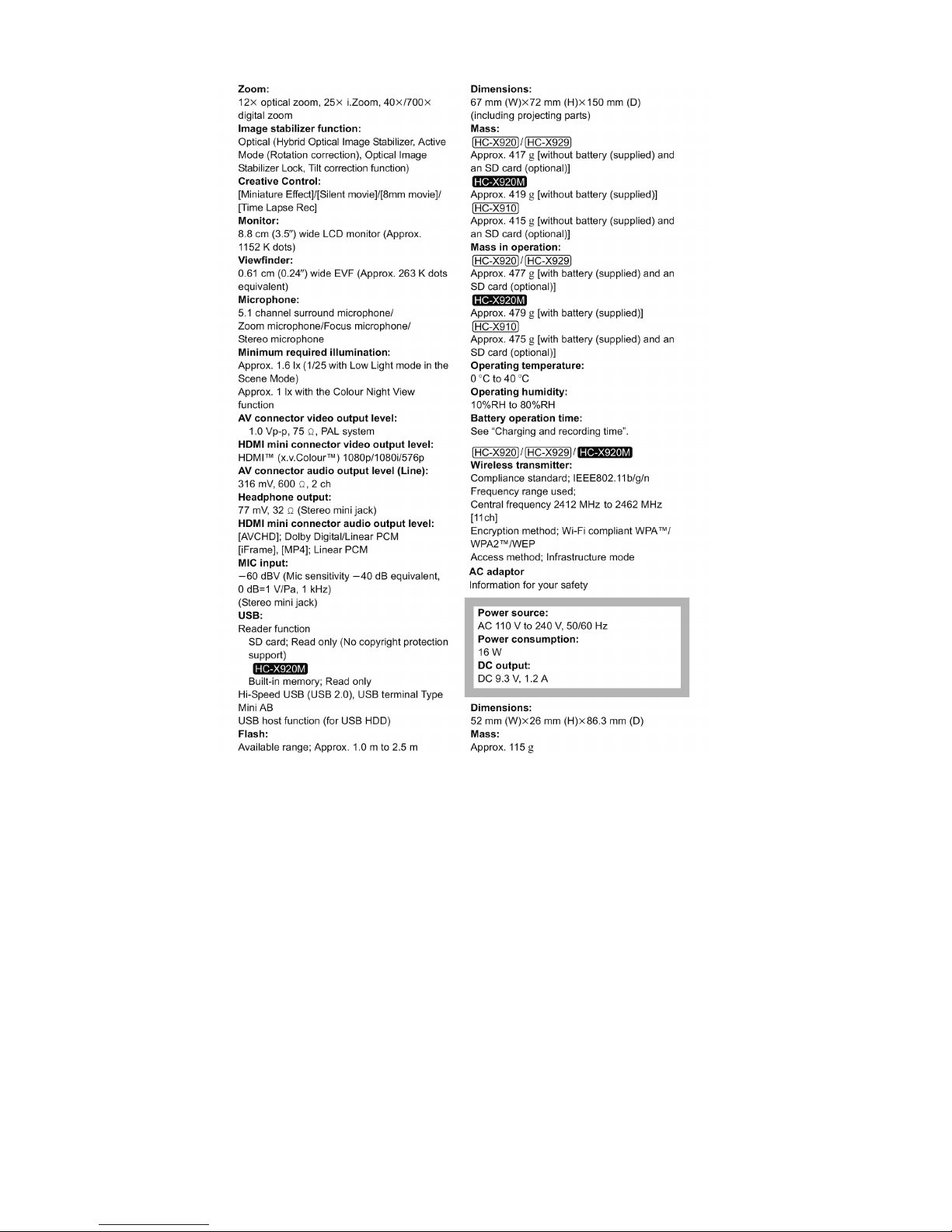
4.2. For PAL Areas
18
19
20
21
22
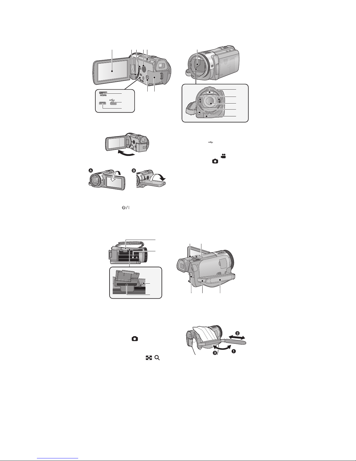
5 Location of Controls and Components
1 LCD monitor (Touch screen)
It can open up to 90Q .
Itcanrotateupto180Q towards the lens or
90Q towards the opposite direction.
2 Power button [ ]
3 Speaker
4 Inlet (cooling fan)
5 Intelligent auto button [iA]
6 Battery release lever [BATT]
7 Battery holder
8 HDMI mini connector [HDMI]
9 USB terminal [ ]
10 A/V connector [A/V]
11 Lens cover
The lens cover opens in Motion Picture
Recording Mode or Still Picture
Recording Mode.
12 Built-in flash
13 3D Conversion Lens attachment part
(concave)
14 Lens (LEICA DICOMAR)
15 AF assist lamp
16 Recording lamp
A/V
8
10
9
11
14
12
15
16
13
67
453
21
●
●
●
17 SD card cover
18 Tripod receptacle
If you attach a tripod which has 5.5 mm
(0.22 S) screw or larger, it may damage this
unit.
19 Access lamp [ACCESS]
20 Card slot
21 Photoshot button [ ]
22 Zoom lever [W/T] (In Motion Picture
Recording Mode or Still Picture
Recording Mode)
Thumbnail display switch [ / ]/
Volume lever [UVOLT] (In Playback
Mode)
23 Recording start/stop button
24 Shoulder strap fixture
25 Grip belt
Adjust the length of the grip belt so that it fits
your hand.
Flip the belt.
Adjust the length.
Replace the belt.
19
20
18
17
1222
23 24 25
●
23
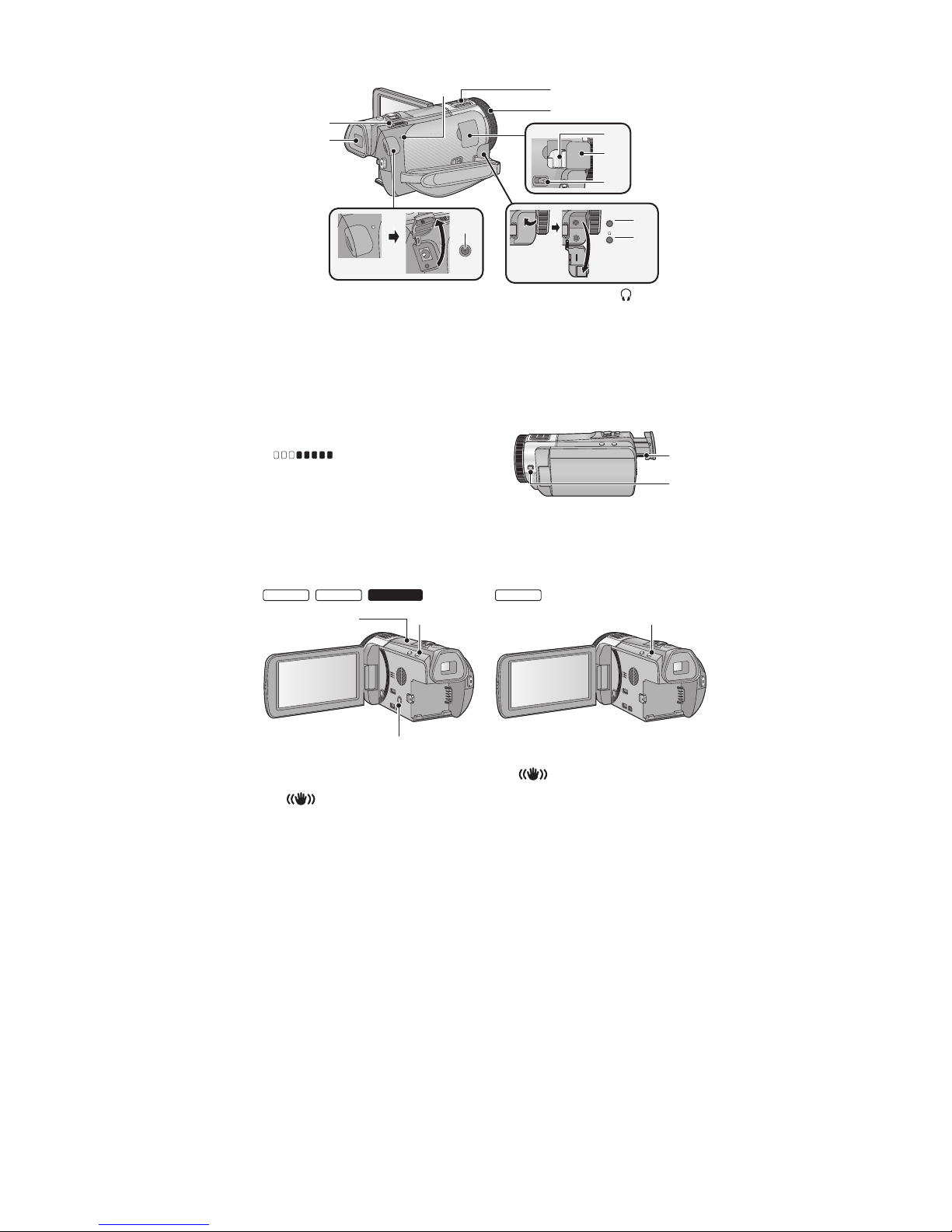
26 Status indicator
27 Internal microphones
28 Multimanualring
29 Shoe adaptor mounting part
30 Shoe adaptor cover
31 Shoe adaptor release lever
[SHOE ADAPTOR RELEASE]
32 Microphone terminal [MIC]
A compatible plug-in powered microphone
can be used as an external microphone.
Audio will be stereo (2 ch) with the external
microphone input.
(Microphone input level meter)
is displayed when the external microphone is
connected.
When the unit is connected with the AC
adaptor, sometimes noise may be heard
depending on the microphone type. In this
case, please switch to the battery for the
power supply and the noise will stop.
33 Headphone terminal [ ]
Excessive sound pressure from earphones
and headphones can cause hearing loss.
Listening at full volume for long periods may
damage the user ’s ears.
34 DC input terminal [DC IN]
Do not use any other AC adaptors except the
supplied one.
35 Mode switch
36 Viewfinder
37 Eyepiece corrector dial
38 Camera function button
[CAMERA FUNCTION]
MIC
32
33
36
35
26
27
28
29
30
31
34
37
38
●
●
●
●
●
●
●
39 Wi-Fi Transmitter
40 Wi-Fi button [Wi-Fi]
41 Optical Image Stabilizer button
[ O.I.S.]
42 Optical Image Stabilizer button
[ O.I.S.]
41
40
39
HC-X910
42
//
HC-X920 HC-X929 HC-X920M
 Loading...