


HC-V270PP
Table of contents
 Loading...
Panasonic HC-V270PP, HC-V270PU, HC-V270EB, HC-V270EC, HC-V270EE Service Manual
...
ORDER NO.VM1501005CE
High Definition Video Camera
Model No. HC-V270PP
HC-V270PU
HC-V270EB
HC-V270EC
HC-V270EE
HC-V270EF
B27
HC-V270EG
HC-V270EP
HC-V270GC
HC-V270GK
HC-V270GN
HC-V270GW
HC-V260EE
Colour
(K)...........Black Type
(R)...........Red Type (only HC-V270EG/EP/GC/GK)
(W)...........White Type (only HC-V270GC/V260EE)
© Panasonic Corporation 2015 Unauthorized copying and distribution is a violation of law.
TABLE OF CONTENTS
PAG E PAG E
1 Safety Precautions -----------------------------------------------3
1.1. General Guidelines ----------------------------------------3
1.2. Leakage Current Cold Check ---------------------------3
1.3. Leakage Current Hot Check (See Figure. 1) --------3
2Warning--------------------------------------------------------------4
2.1. Prevention of Electrostatic Discharge (ESD)
to Electrostatically Sensitive (ES) Devices ----------4
2.2. How to Recycle the Lithium Ion Battery (U.S.
Only)-----------------------------------------------------------4
2.3. Caution for AC Cord (For EB/GC) ---------------------5
2.4. How to Replace the Lithium Battery -------------------6
3 Service Navigation------------------------------------------------7
3.1. Introduction --------------------------------------------------7
3.2. General Description About Lead Free Solder
(PbF) ----------------------------------------------------------7
3.3. How to Define the Model Suffix (NTSC or PAL
model)---------------------------------------------------------8
3.4. Formatting----------------------------------------------------9
3.5. Baking of replacement IC and defective P.C.B.
----------------------------------------------------------------10
4 Specifications ---------------------------------------------------- 11
5 Location of Controls and Components------------------ 13
6 Service Mode ----------------------------------------------------- 16
6.1. Model/Destination Settings ---------------------------- 17
6.2. Lock Search and Error History Indication ---------- 18
6.3. Power ON Self Check Result Display--------------- 19
6.4. Adjustment function for the Service ----------------- 20
6.5. Restore the backed up adjustment data------------ 21
6.6. Touch Panel Calibration -------------------------------- 22
6.7. NFC Initialization (HC-V270 only)-------------------- 22
7 Service Fixture & Tools --------------------------------------- 23
7.1. Service Fixture and Tools ------------------------------ 23
7.2. When Replacing the Main P.C.B. -------------------- 23
7.3. Service Position ------------------------------------------ 23
8 Disassembly and Assembly Instructions --------------- 24
8.1. Disassembly Flow Chart for the Unit ---------------- 24
8.2. PCB Location---------------------------------------------- 25
8.3. Disassembly Procedure for the Unit ---------------- 26
9 Measurements and Adjustments -------------------------- 43
9.1. Electric Adjustment --------------------------------------43
10 Factory Setting--------------------------------------------------- 55
10.1. How To Turn On The Factory Settings? ------------ 55
10.2. What Is The Factory Settings? ----------------------- 56
11 Block Diagra m --------------------------------------------------- 57
11.1. Overall Block Diagram ----------------------------------57
11.2. Camera/System Control Circuit Block
Diagram----------------------------------------------------- 58
11.3. Video/Audio Signal Process(1) Circuit Block
Diagram----------------------------------------------------- 59
11.4. Video/Audio Signal Process(2) Circuit Block
Diagram----------------------------------------------------- 60
11.5. Lens Drive Circuit Block Diagram -------------------- 61
11.6. Power Supply Circuit Block Diagram---------------- 62
12 Wiring Connection Diagram --------------------------------- 63
12.1. Interconnection Diagram ------------------------------- 63
2
1 Safety Precautions
1.1. General Guidelines
1. IMPORTANT SAFETY NOTICE
There are special components used in this equipment
which are important for safety. These parts are marked by
in the Schematic Diagrams, Circuit Board Layout,
Exploded Views and Replacement Parts List. It is essen-
tial that these critical parts should be replaced with manu-
facturer’s specified parts to prevent X-RADIATION,
shock, fire, or other hazards. Do not modify the original
design without permission of manufacturer.
2. An Isolation Transformer should always be used during
the servicing of AC Adaptor whose chassis is not isolated
from the AC power line. Use a transformer of adequate
power rating as this protects the technician from acci-
dents resulting in personal injury from electrical shocks. It
will also protect AC Adaptor from being damaged by acci-
dental shorting that may occur during servicing.
3. When servicing, observe the original lead dress. If a short
circuit is found, replace all parts which have been over-
heated or damaged by the short circuit.
4. After servicing, see to it that all the protective devices
such as insulation barriers, insulation papers shields are
properly installed.
5. After servicing, make the following leakage current
checks to prevent the customer from being exposed to
shock hazards.
1.3. Leakage Current Hot Check (See Figure. 1)
1. Plug the AC cord directly into the AC outlet. Do not use
an isolation transformer for this check.
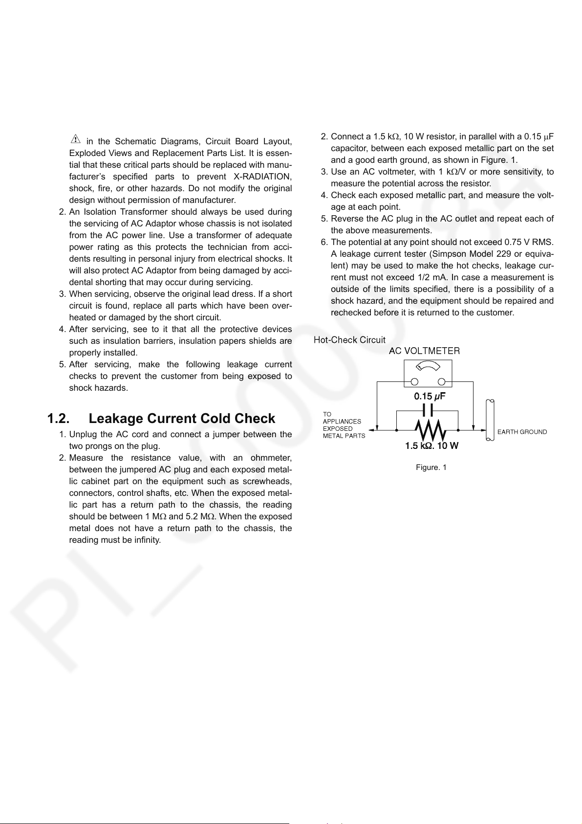
2. Connect a 1.5 k, 10 W resistor, in parallel with a 0.15 F
capacitor, between each exposed metallic part on the set
and a good earth ground, as shown in Figure. 1.
3. Use an AC voltmeter, with 1 k/V or more sensitivity, to
measure the potential across the resistor.
4. Check each exposed metallic part, and measure the volt-
age at each point.
5. Reverse the AC plug in the AC outlet and repeat each of
the above measurements.
6. The potential at any point should not exceed 0.75 V RMS.
A leakage current tester (Simpson Model 229 or equiva-
lent) may be used to make the hot checks, leakage cur-
rent must not exceed 1/2 mA. In case a measurement is
outside of the limits specified, there is a possibility of a
shock hazard, and the equipment should be repaired and
rechecked before it is returned to the customer.
1.2. Leakage Current Cold Check
1. Unplug the AC cord and connect a jumper between the
two prongs on the plug.
2. Measure the resistance value, with an ohmmeter,
between the jumpered AC plug and each exposed metal-
lic cabinet part on the equipment such as screwheads,
connectors, control shafts, etc. When the exposed metal-
lic part has a return path to the chassis, the reading
should be between 1 M and 5.2 M. When the exposed
metal does not have a return path to the chassis, the
reading must be infinity.
Figure. 1
3
2Warning
2.1. Prevention of Electrostatic Discharge (ESD) to Electrostatically Sensitive (ES) Devices
Some semiconductor (solid state) devices can be damaged easily by static electricity. Such components commonly are called Electrostatically Sensitive (ES) Devices. Examples of typical ES devices are integrated circuits and some field-effect transistors and
semiconductor "chip" components. The following techniques should be used to help reduce the incidence of component damage
caused by electrostatic discharge (ESD).
1. Immediately before handling any semiconductor component or semiconductor-equipped assembly, drain off any ESD on your
body by touching a known earth ground. Alternatively, obtain and wear a commercially available discharging ESD wrist strap,
which should be removed for potential shock reasons prior to applying power to the unit under test.
2. After removing an electrical assembly equipped with ES devices, place the assembly on a conductive surface such as alumi-
num foil, to prevent electrostatic charge buildup or exposure of the assembly.
3. Use only a grounded-tip soldering iron to solder or unsolder ES devices.
4. Use only an antistatic solder removal device. Some solder removal devices not classified as “antistatic (ESD protected)” can
generate electrical charge sufficient to damage ES devices.
5. Do not use freon-propelled chemicals. These can generate electrical charges sufficient to damage ES devices.
6. Do not remove a replacement ES device from its protective package until immediately before you are ready to install it. (Most
replacement ES devices are packaged with leads electrically shorted together by conductive foam, aluminum foil or compara-
ble conductive material).
7. Immediately before removing the protective material from the leads of a replacement ES device, touch the protective material
to the chassis or circuit assembly into which the device will be installed.
CAUTION :
Be sure no power is applied to the chassis or circuit, and observe all other safety precautions.
8. Minimize bodily motions when handling unpackaged replacement ES devices. (Otherwise harmless motion such as the
brushing together of your clothes fabric or the lifting of your foot from a carpeted floor can generate static electricity (ESD) suf-
ficient to damage an ES device).
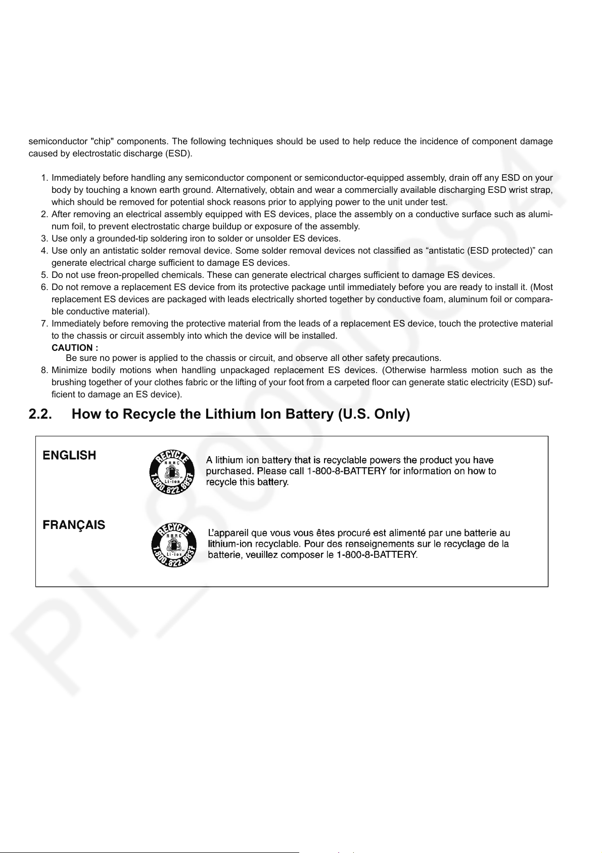
2.2. How to Recycle the Lithium Ion Battery (U.S. Only)
4
2.3. Caution for AC Cord (For EB/GC)
2.3.1. Information for Your Safety
IMPORTANT
Your attention is drawn to the fact that recording of prerecorded tapes or discs or other published or broadcast
material may infringe copyright laws.
WARNING
To reduce the risk of fire or shock hazard, do not expose
this equipment to rain or moisture.
CAUTION
To reduce the risk of fire or shock hazard and annoying
interference, use the recommended accessories only.
FOR YOUR SAFETY
DO NOT REMOVE THE OUTER COVER
To prevent electric shock, do not remove the cover. No user
serviceable parts inside. Refer servicing to qualified service
personnel.
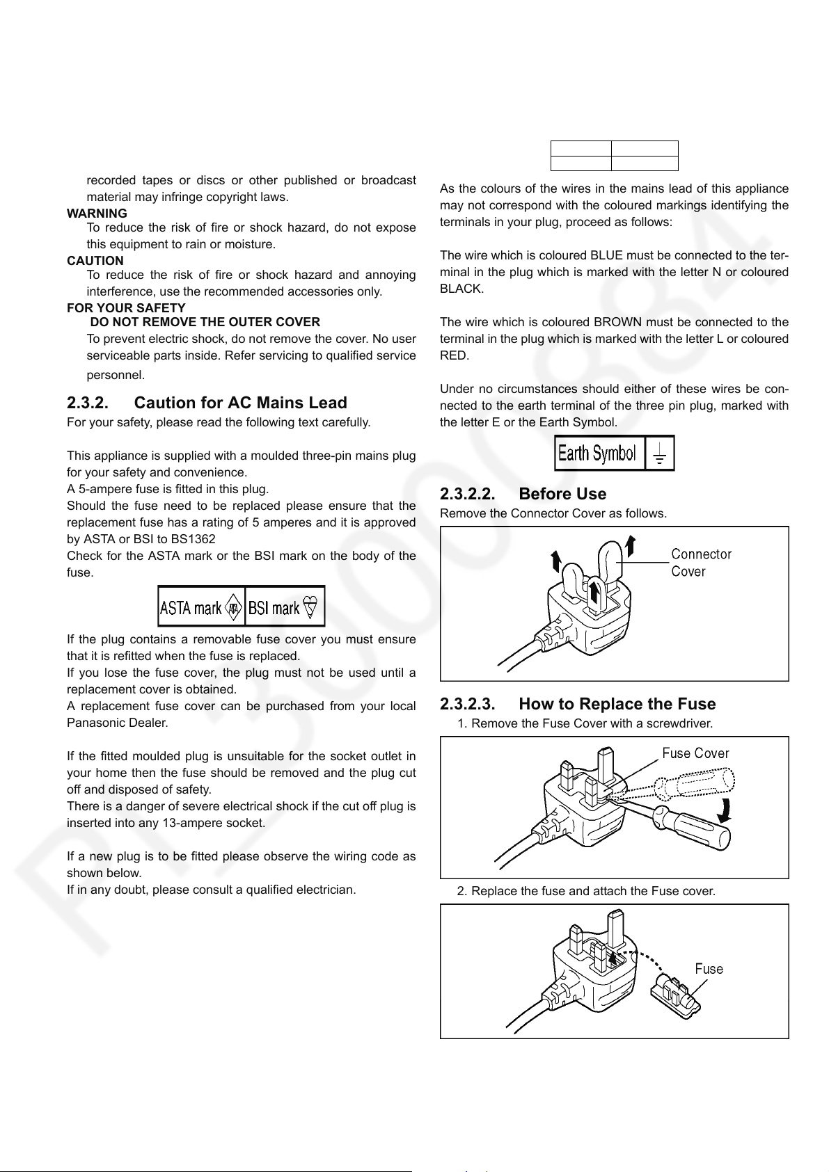
2.3.2. Caution for AC Mains Lead
For your safety, please read the following text carefully.
This appliance is supplied with a moulded three-pin mains plug
for your safety and convenience.
A 5-ampere fuse is fitted in this plug.
Should the fuse need to be replaced please ensure that the
replacement fuse has a rating of 5 amperes and it is approved
by ASTA or BSI to BS1362
Check for the ASTA mark or the BSI mark on the body of the
fuse.
2.3.2.1. Important
The wires in this mains lead are coloured in accordance with
the following code:
Blue Neutral
Brown Live
As the colours of the wires in the mains lead of this appliance
may not correspond with the coloured markings identifying the
terminals in your plug, proceed as follows:
The wire which is coloured BLUE must be connected to the ter-
minal in the plug which is marked with the letter N or coloured
BLACK.
The wire which is coloured BROWN must be connected to the
terminal in the plug which is marked with the letter L or coloured
RED.
Under no circumstances should either of these wires be con-
nected to the earth terminal of the three pin plug, marked with
the letter E or the Earth Symbol.
2.3.2.2. Before Use
Remove the Connector Cover as follows.
If the plug contains a removable fuse cover you must ensure
that it is refitted when the fuse is replaced.
If you lose the fuse cover, the plug must not be used until a
replacement cover is obtained.
A replacement fuse cover can be purchased from your local
Panasonic Dealer.
If the fitted moulded plug is unsuitable for the socket outlet in
your home then the fuse should be removed and the plug cut
off and disposed of safety.
There is a danger of severe electrical shock if the cut off plug is
inserted into any 13-ampere socket.
If a new plug is to be fitted please observe the wiring code as
shown below.
If in any doubt, please consult a qualified electrician.
2.3.2.3. How to Replace the Fuse
1. Remove the Fuse Cover with a screwdriver.
2. Replace the fuse and attach the Fuse cover.
5
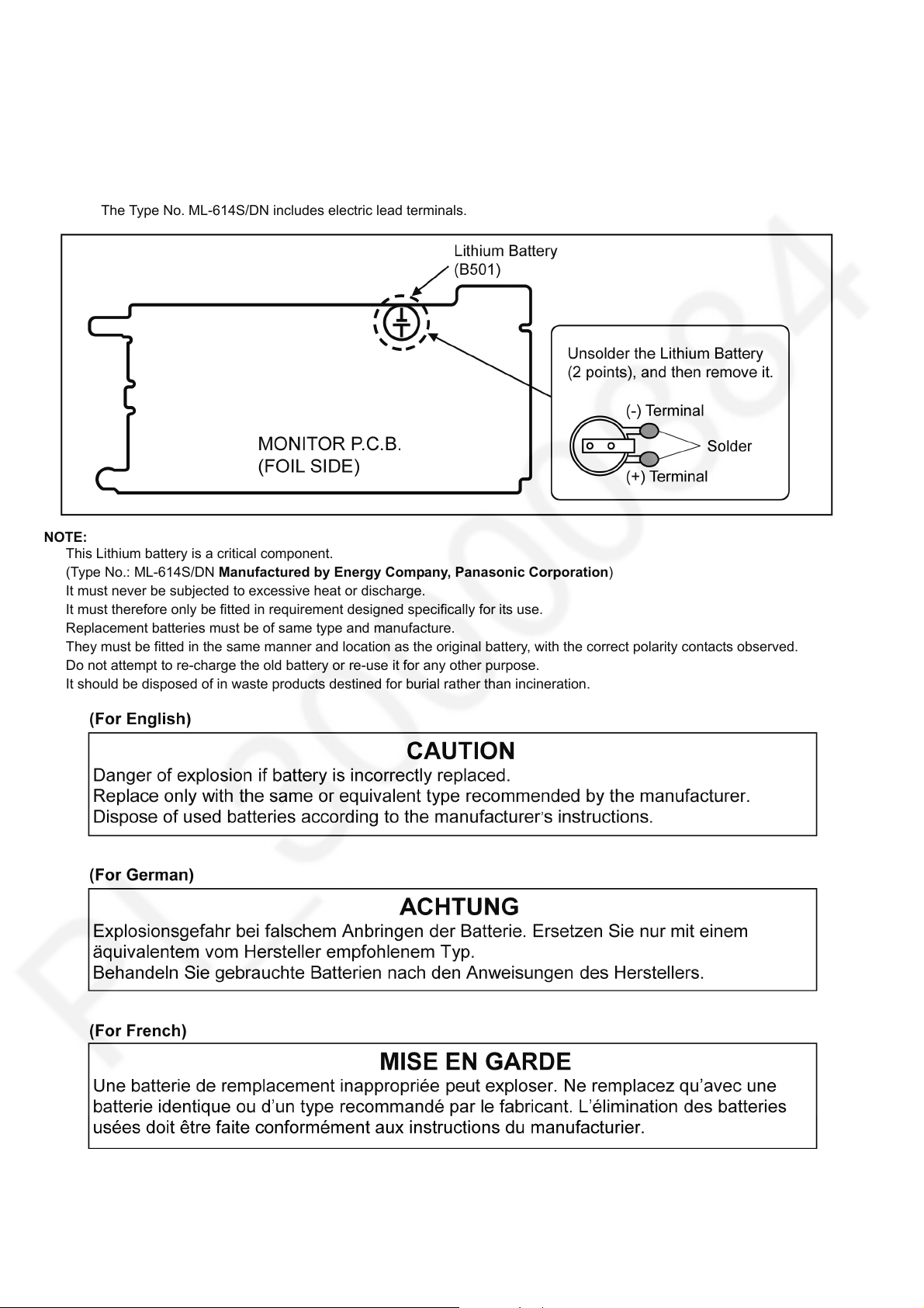
2.4. How to Replace the Lithium Battery
2.4.1. Replacement Procedure
1. Remove the MONITOR P.C.B.. (Refer to Disassembly Procedures.)
2. Unsolder the each soldering point of electric lead terminal for Lithium battery (Ref. No. “B501” at foil side of MONITOR
P.C.B.) and remove the Lithium battery together with electric lead terminal. Then replace it into new one.
NOTE:
The Type No. ML-614S/DN includes electric lead terminals.
NOTE:
This Lithium battery is a critical component.
(Type No.: ML-614S/DN Manufactured by Energy Company, Panasonic Corporation)
It must never be subjected to excessive heat or discharge.
It must therefore only be fitted in requirement designed specifically for its use.
Replacement batteries must be of same type and manufacture.
They must be fitted in the same manner and location as the original battery, with the correct polarity contacts observed.
Do not attempt to re-charge the old battery or re-use it for any other purpose.
It should be disposed of in waste products destined for burial rather than incineration.
NOTE:
Above caution is applicable for a battery pack which is for HC-V270/V260 series, as well.
6
3 Service Navigation
3.1. Introduction
This service manual contains technical information, which allow service personnel’s to understand and service this model.
Please place orders using the parts list and not the drawing reference numbers.
If the circuit is changed or modified, the information will be followed by service manual to be controlled with original service manual.
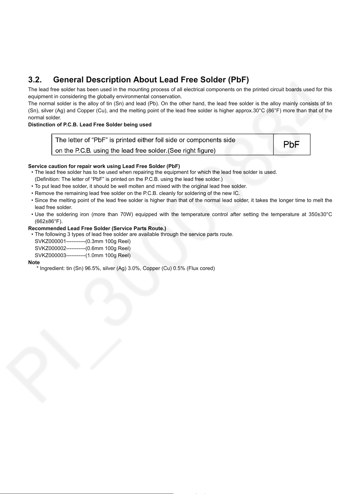
3.2. General Description About Lead Free Solder (PbF)
The lead free solder has been used in the mounting process of all electrical components on the printed circuit boards used for this
equipment in considering the globally environmental conservation.
The normal solder is the alloy of tin (Sn) and lead (Pb). On the other hand, the lead free solder is the alloy mainly consists of tin
(Sn), silver (Ag) and Copper (Cu), and the melting point of the lead free solder is higher approx.30°C (86°F) more than that of the
normal solder.
Distinction of P.C.B. Lead Free Solder being used
Service caution for repair work using Lead Free Solder (PbF)
• The lead free solder has to be used when repairing the equipment for which the lead free solder is used.
(Definition: The letter of “PbF” is printed on the P.C.B. using the lead free solder.)
• To put lead free solder, it should be well molten and mixed with the original lead free solder.
• Remove the remaining lead free solder on the P.C.B. cleanly for soldering of the new IC.
• Since the melting point of the lead free solder is higher than that of the normal lead solder, it takes the longer time to melt the
lead free solder.
• Use the soldering iron (more than 70W) equipped with the temperature control after setting the temperature at 350±30°C
(662±86°F).
Recommended Lead Free Solder (Service Parts Route.)
• The following 3 types of lead free solder are available through the service parts route.
SVKZ000001-----------(0.3mm 100g Reel)
SVKZ000002-----------(0.6mm 100g Reel)
SVKZ000003-----------(1.0mm 100g Reel)
Note
* Ingredient: tin (Sn) 96.5%, silver (Ag) 3.0%, Copper (Cu) 0.5% (Flux cored)
7
3.3. How to Define the Model Suffix (NTSC or PAL model)
There are eight kinds of HC-V270/V260.
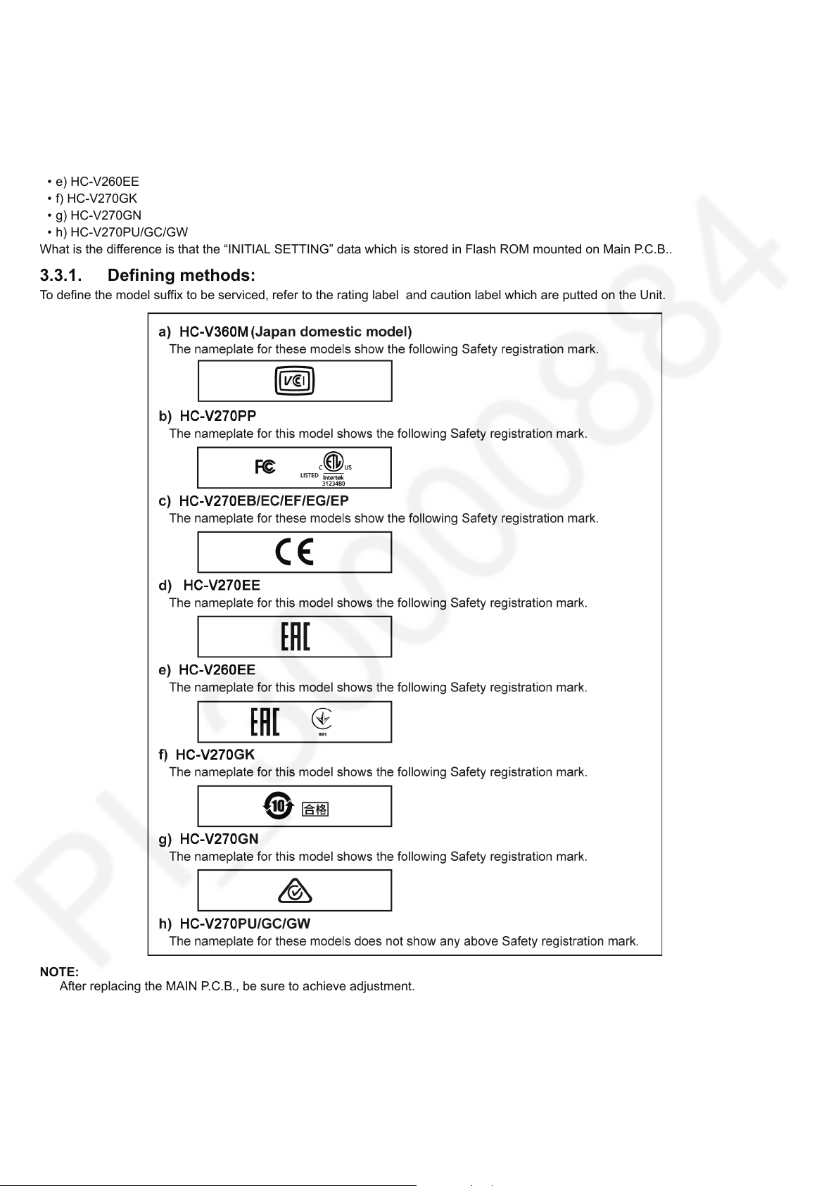
• a) HC-V360M (Japan domestic model)
• b) HC-V270PP
• c) HC-V270EB/EC/EF/EG/EP
• d) HC-V270EE
• e) HC-V260EE
• f) HC-V270GK
• g) HC-V270GN
• h) HC-V270PU/GC/GW
What is the difference is that the “INITIAL SETTING” data which is stored in Flash ROM mounted on Main P.C.B..
3.3.1. Defining methods:
To define the model suffix to be serviced, refer to the rating label and caution label which are putted on the Unit.
NOTE:
After replacing the MAIN P.C.B., be sure to achieve adjustment.
8
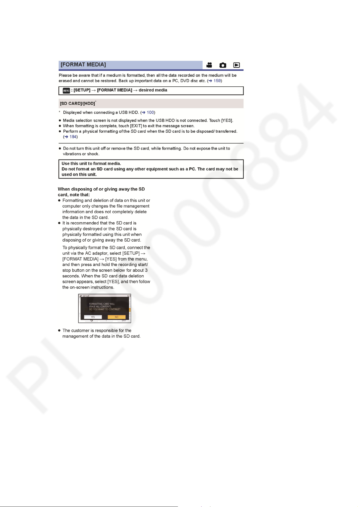
3.4. Formatting
The following formatting is for HC-V270PP.
The page number in this page does not show the page number of this service manual.
9
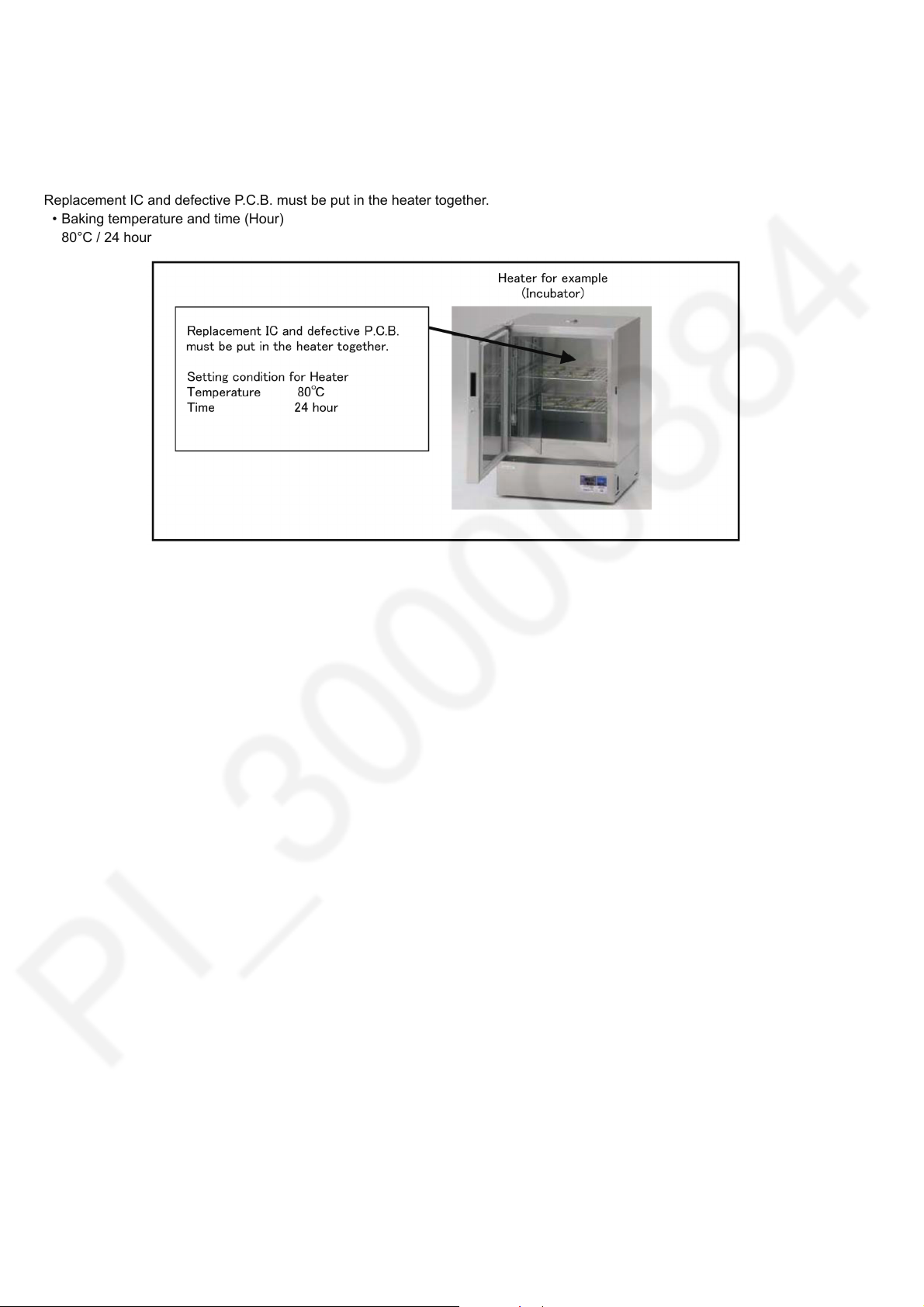
3.5. Baking of replacement IC and defective P.C.B.
When replacing the CSP/BGA/QFN type IC mounted on the P.C.B., the problem of IC crack or foil pattern breaking in the P.C.B.
might sometimes occur by rapid heating.
In order to improve the success rate of IC replacement for repair, it would be required to work out baking of replacement
IC and defective P.C.B. before replacing IC.
Please refer the way of baking as follows.
Replacement IC and defective P.C.B. must be put in the heater together.
• Baking temperature and time (Hour)
80°C / 24 hour
10
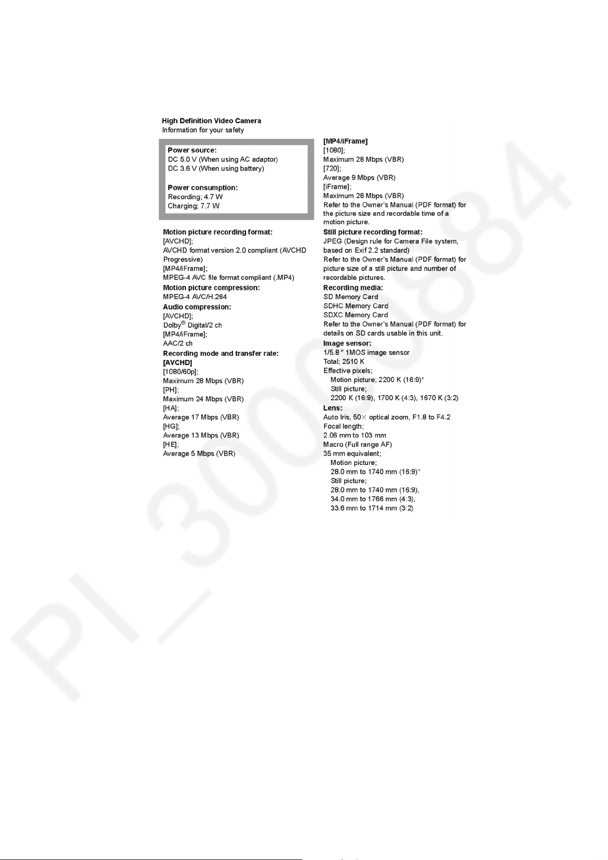
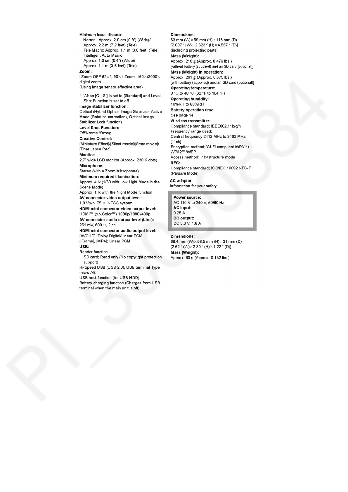
4 Specifications
The following specification is for HC-V270PP.
Some specifications may differ depending on model suffix.
The page number in this chapter does not show the page number of this service manual.
11
12
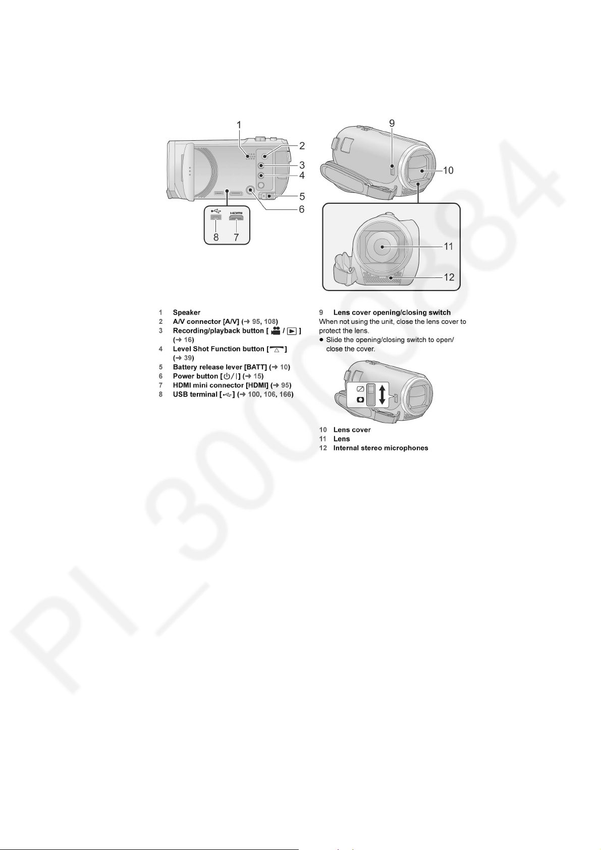
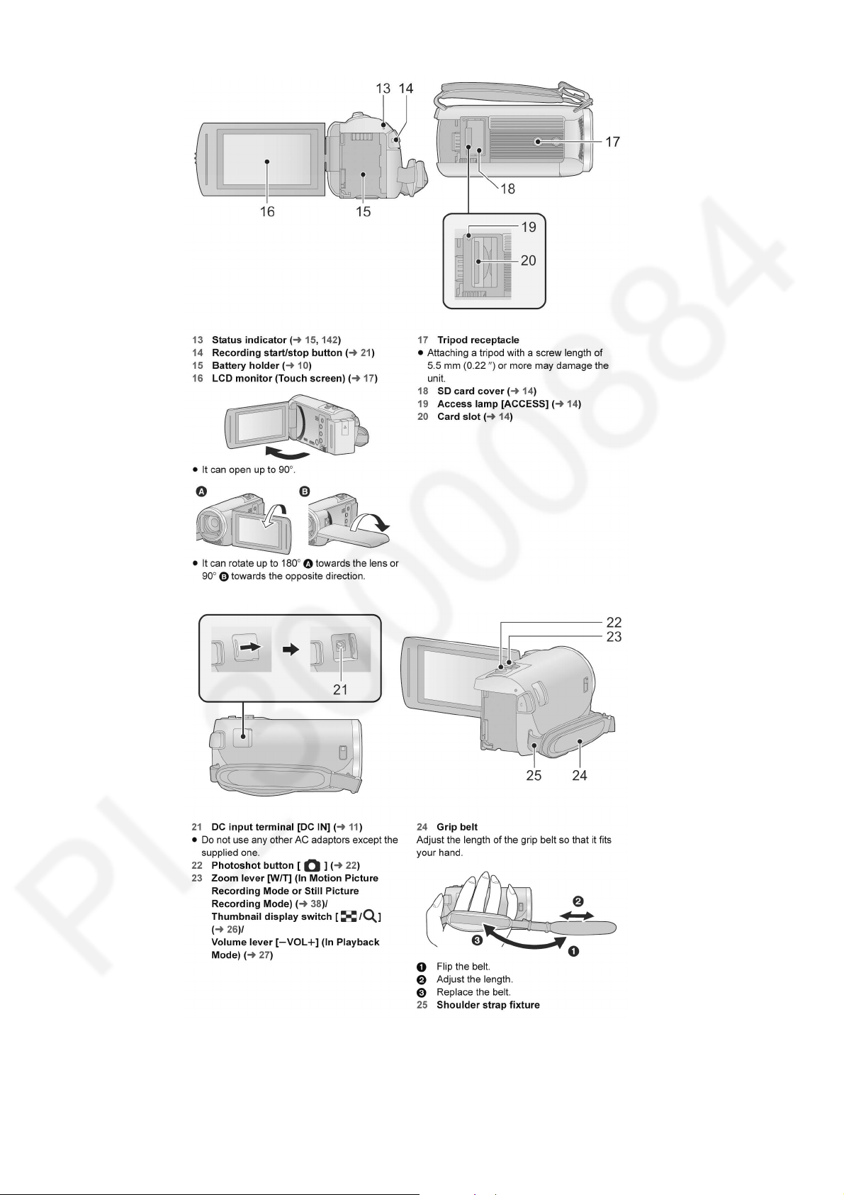
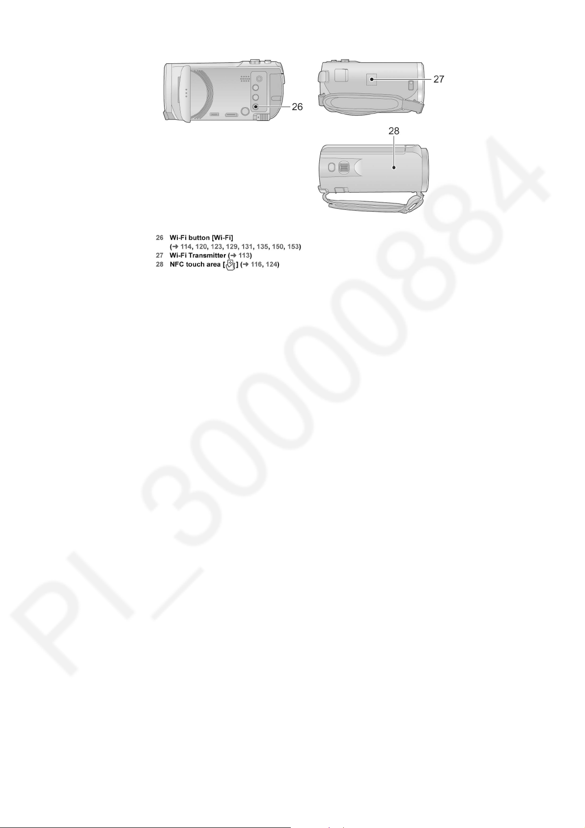
5 Location of Controls and Components
The following description is for HC-V270PP.
Some descriptions may differ depending on model suffix.
The page number in this chapter does not show the page number of this service manual.
13
141516
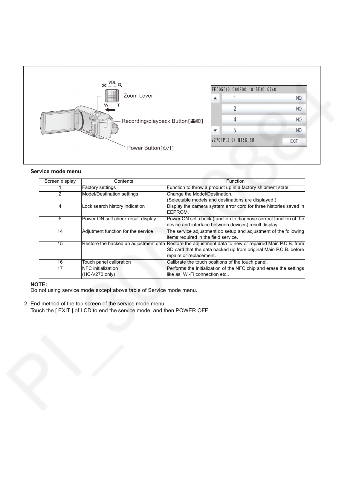
6 Service Mode
Indication method of the service menu
1. Keep pressing the “Power” button, “Zoom lever” to W side and “Recording/Playback” button for more than 3 seconds until the
top screen of the Service Mode Menu being displayed.
Service mode menu
Screen display Contents Function
1 Factory settings Function to throw a product up in a factory shipment state.
2 Model/Destination settings Change the Model/Destination.
4 Lock search history indication Display the camera system error cord for three histories saved in
5 Power ON self check result display Power ON self check (function to diagnose correct function of the
14 Adjutment function for the service The service adjustment do setup and adjustment of the following
15 Restore the backed up adjustment data Restore the adjustment data to new or repaired Main P.C.B. from
16 Touch panel calibration Calibrate the touch positions of the touch panel.
17 NFC initialization
(HC-V270 only)
(Selectable models and destinations are displayed.)
EEPROM.
device and interface between devices) result display.
items required in the field service.
SD card that the data backed up from original Main P.C.B. before
repairs or replacement.
Performs the Initialization of the NFC chip and erase the settings
like as Wi-Fi connection etc..
NOTE:
Do not using service mode except above table of Service mode menu.
2. End method of the top screen of the service mode menu
Touch the [ EXIT ] of LCD to end the service mode, and then POWER OFF.
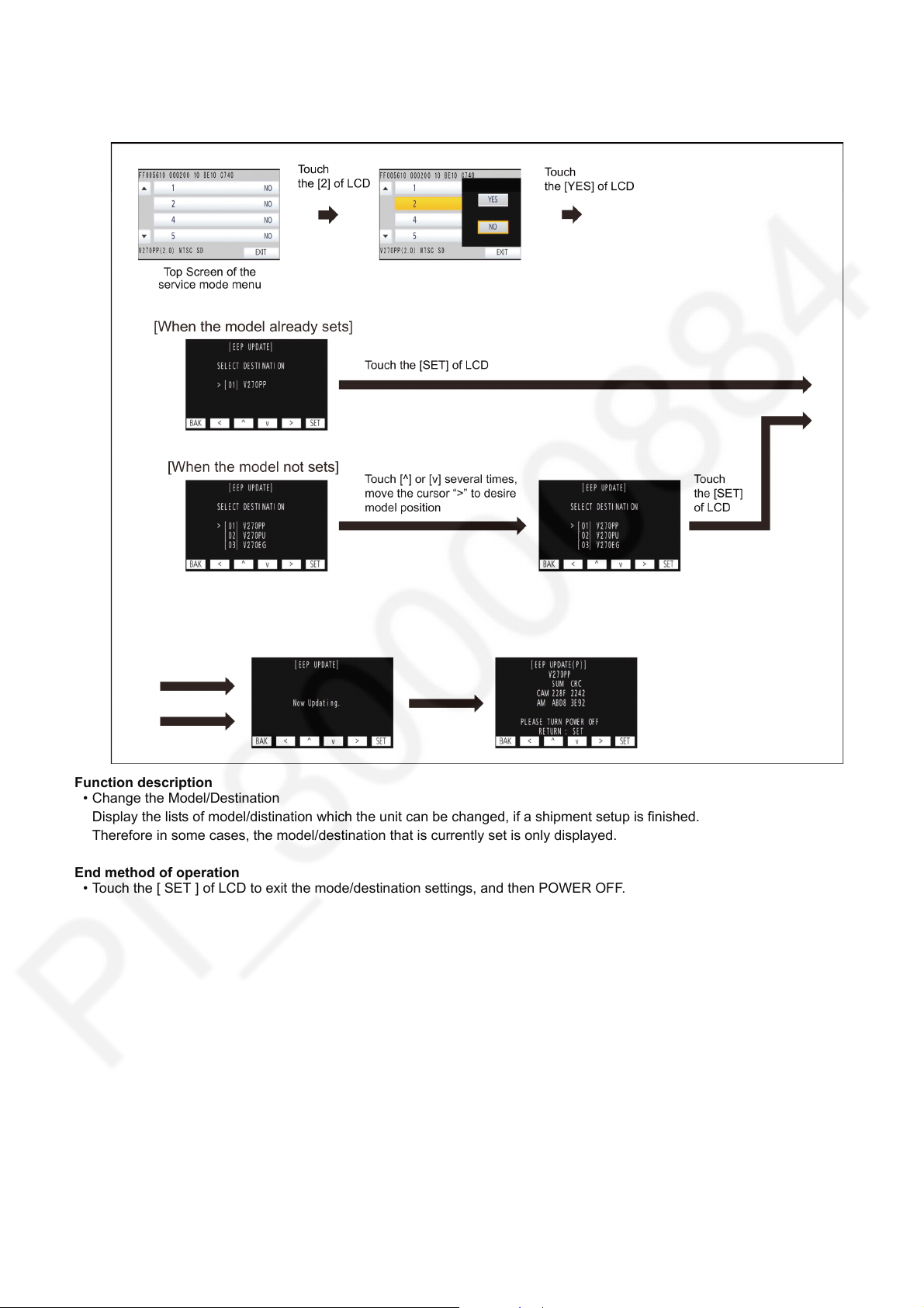
6.1. Model/Destination Settings
Touch the [ 2 ] of LCD, select model/destination settings.
Operation specifications
Function description
• Change the Model/Destination
Display the lists of model/distination which the unit can be changed, if a shipment setup is finished.
Therefore in some cases, the model/destination that is currently set is only displayed.
End method of operation
• Touch the [ SET ] of LCD to exit the mode/destination settings, and then POWER OFF.
17
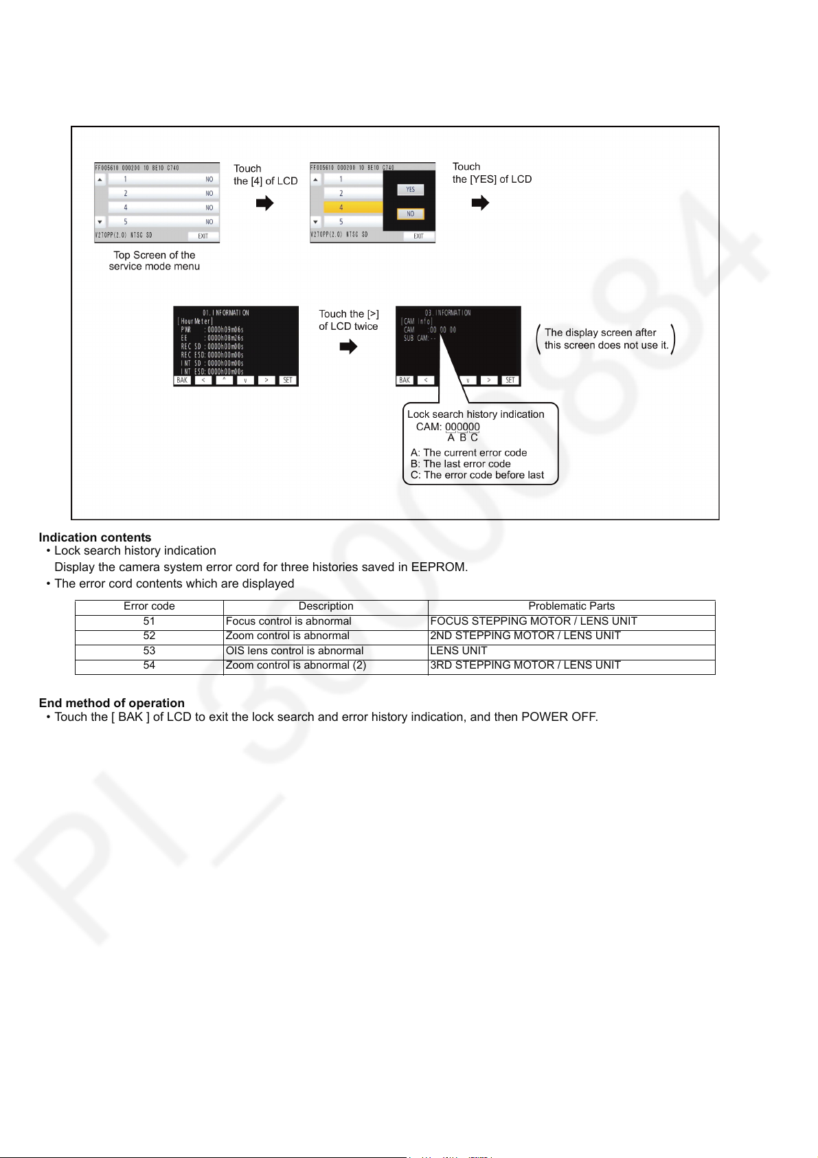
6.2. Lock Search and Error History Indication
Touch the [ 4 ] of LCD, select Lock search and error history indication.
Operation specifications
Indication contents
• Lock search history indication
Display the camera system error cord for three histories saved in EEPROM.
• The error cord contents which are displayed
Error code Description Problematic Parts
51 Focus control is abnormal FOCUS STEPPING MOTOR / LENS UNIT
52 Zoom control is abnormal 2ND STEPPING MOTOR / LENS UNIT
53 OIS lens control is abnormal LENS UNIT
54 Zoom control is abnormal (2) 3RD STEPPING MOTOR / LENS UNIT
End method of operation
• Touch the [ BAK ] of LCD to exit the lock search and error history indication, and then POWER OFF.
18
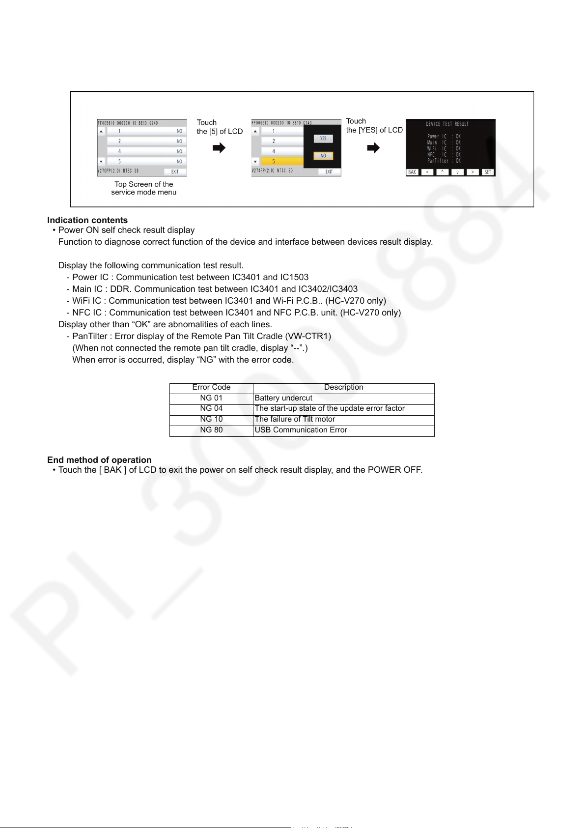
6.3. Power ON Self Check Result Display
Touch the [ 5 ] of LCD, select Power ON self check result display.
Operation specifications
Indication contents
• Power ON self check result display
Function to diagnose correct function of the device and interface between devices result display.
Display the following communication test result.
- Power IC : Communication test between IC3401 and IC1503
- Main IC : DDR. Communication test between IC3401 and IC3402/IC3403
- WiFi IC : Communication test between IC3401 and Wi-Fi P.C.B.. (HC-V270 only)
- NFC IC : Communication test between IC3401 and NFC P.C.B. unit. (HC-V270 only)
Display other than “OK” are abnomalities of each lines.
- PanTilter : Error display of the Remote Pan Tilt Cradle (VW-CTR1)
(When not connected the remote pan tilt cradle, display “--”.)
When error is occurred, display “NG” with the error code.
Error Code Description
NG 01 Battery undercut
NG 04 The start-up state of the update error factor
NG 10 The failure of Tilt motor
NG 80 USB Communication Error
End method of operation
• Touch the [ BAK ] of LCD to exit the power on self check result display, and the POWER OFF.
19
Loading...