


FP2/FP2SH Series
Programmable Controllers
08/2007
CPU Units
Top Performance, Full Range of Functions
CPU units
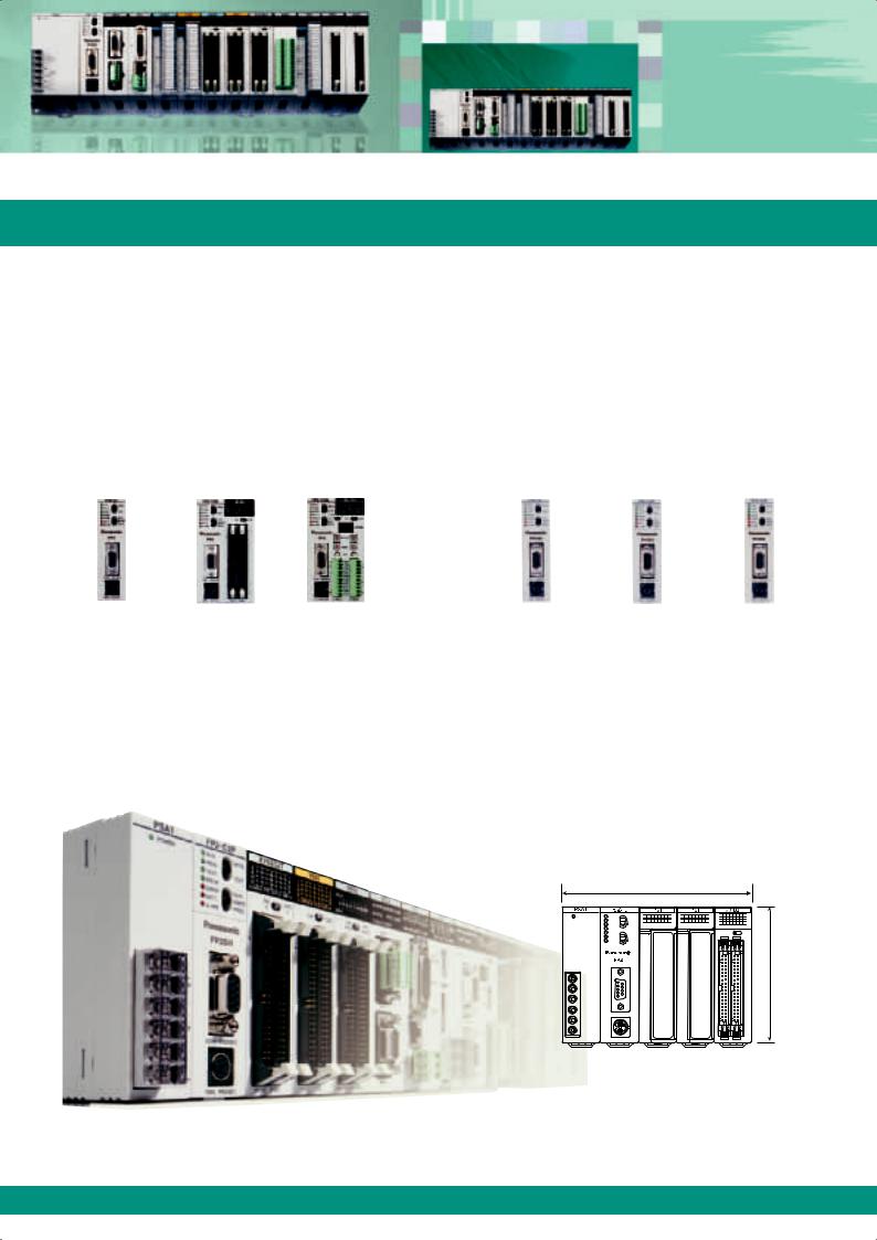
Selectable from six types, according to the application
There are six types of CPU units, including the standard type and the type with preinstalled commonly-used advanced functions. This selection allows for more economical system development according to the application. See page 12 for details.
FP2 |
FP2SH |
Superior cost performance |
Industry‘s highest class processing speed |
|
Adequate programming capacity |
Standard type |
With 64 input points |
With S-LINK |
60k step |
60k step type |
120k step type |
FP2-C1 |
FP2-C1D |
FP2-C1SL |
standard type |
for small PC card |
for small PC card |
|
|
|
FP2-C2 |
FP2-C2P |
FP2-C3P |
Body size
The front face is smaller than an A6 sheet of paper
The front face area is 140mm wide and 100mm high (when using five modules), which is small enough to fit completely on an A6 sheet of paper. The compact body requires minimum installation space. (Depth: 108.3mm)
140mm

100mm
|
08/2007 |

Memory and I/O Control
Flexible Expandability
Memory and I/O control
Equipped with an adequate program memory and operating memory capacity
The body is compact; however, the standard program memory capacity of FP2/FP2SH is as large as 16k/60k steps, and when optional memory is added, 32k/120k steps. A variety of operation memory types are also available. The maximum number of controlled I/O points is 2,048 (2,048/8,192 for FP2/FP2SH when using remote I/O units), which is sufficient for medium-scale control.
Addition of optional memory
FP2: |
Addition of optional memory to the CPU unit allows it |
|
to store up to 32k program steps, provides it with the |
|
clock/calendar function, and makes comment writing |
|
possible. |
FP2SH: |
An optional IC card can be used as program memory |
|
or expanded data memory. |
I/O point expansion by adding backplanes
See page 14 for details.
|
NEW! |
Conventional backplane |
H type backplane |
Optional memory for FP2SH
Only one backplane can be added to one master backplane. When both the master and expansion backplanes are of the 14module type, up to 1,600 I/O points can be controlled.
Up to three backplanes can be added to one master backplane. Now up to 32 units can be connected and up to 2,048 I/O points controlled.
CPU backplane |
|
|
|
|
|
|
|
|
|
|
|
|
|
|
Master backplane (8 slots) |
|
|
|
|
|
|
|
|
|
|
|
|
|
|
|
||||||||||||||||||||||||||||||||||||||||||||||||||
|
|
|
|
|
|
|
|
|
|
|
|
|
|
|
|
|
|
|
|
|
|
|
|
|
|
|
|
|
|
|
|
|
|
|
|
|
|
|
|
|
|
|
|
|
|
|
|
|
|
|
|
|
|
|
|
|
|
|
|
|
|
|
|
|
|
|
|
|
|
|
|
|
|
|
|
|
|
|
|
|
|
|
|
|
|
|
|
|
|
|
|
|
|
|
|
|
|
|
|
|
|
|
|
|
|
|
|
|
|
|
|
|
|
|
|
|
|
|
|
|
|
|
|
|
|
|
|
|
|
|
|
|
|
|
|
|
|
|
|
|
|
|
|
|
|
|
|
|
|
|
|
|
|
|
|
|
|
|
|
|
|
|
|
|
|
|
|
|
|
|
|
|
|
|
|
|
|
|
|
|
|
|
|
|
|
|
|
|
|
|
|
|
|
|
|
|
|
|
|
|
|
|
|
|
|
|
|
|
|
|
|
|
|
|
|
|
|
|
|
|
|
|
|
|
|
|
|
|
|
|
|
|
|
|
|
|
|
|
|
|
|
|
|
|
|
|
|
|
|
|
|
|
|
|
|
|
|
|
|
|
|
|
|
|
|
|
|
|
|
|
|
|
|
|
|
|
|
|
|
|
|
|
|
|
|
|
|
|
|
|
|
|
|
|
|
|
|
|
|
|
|
|
|
|
|
|
|
|
|
|
|
|
|
|
|
|
|
|
|
|
|
|
|
|
|
|
|
|
|
|
|
|
|
|
|
|
|
|
|
|
|
|
|
|
|
|
|
|
|
|
|
|
|
|
|
|
|
|
|
|
|
|
|
|
|
|
|
|
|
|
|
|
|
|
|
|
|
|
|
|
|
|
|
|
|
|
|
|
|
|
|
|
|
|
|
|
|
|
|
|
|
|
|
|
|
|
|
|
|
|
|
|
|
|
|
|
|
|
|
|
|
|
|
|
|
|
|
|
|
|
|
|
|
|
|
|
|
|
|
|
|
|
|
|
|
|
|
|
|
|
|
|
|
|
|
|
|
|
|
|
|
|
|
|
|
|
|
|
|
|
|
|
|
|
|
|
|
|
|
|
|
|
|
|
|
|
|
|
|
|
|
|
|
|
|
|
|
|
|
|
|
|
|
|
|
|
|
|
|
|
|
|
|
|
|
|
|
|
|
|
|
|
|
|
|
|
|
|
|
|
|
|
|
|
|
|
|
|
|
|
|
|
|
|
|
|
|
|
|
|
|
|
|
|
|
|
|
|
|
|
|
|
|
|
|
|
Expansion |
Expansion backplane |
Expansion backplane (8 slots) |
cable |
|
|
|
|
(The backplane can be used as either a master or expansion backplane.)
|
|
|
|
|
|
|
|
|
|
|
|
|
|
|
|
|
|
|
|
|
|
|
|
|
|
|
|
|
|
|
|
|
|
|
|
|
|
|
|
|
|
|
|
|
|
|
|
|
|
|
|
|
|
|
|
|
|
|
|
|
|
|
|
|
|
|
|
|
|
|
|
|
|
|
|
|
|
|
|
|
|
|
|
|
|
|
|
|
|
|
|
|
|
|
|
|
|
|
|
|
|
|
|
|
|
|
|
|
|
|
|
|
|
|
|
|
|
|
|
|
|
|
|
|
|
|
|
|
|
|
|
|
|
|||||||||||||||||||||
|
Conventional type |
H type |
|
|
|
|
|
|
||||||||||||||||||||||
Max. number of backplanes |
1 + 1 = 2 |
1 for master + 3 for expansion = 4 |
|
|
|
|
|
|
|
|
|
|
|
|
|
|
|
|
|
|
|
|
|
|
|
|
|
|
|
|
Max. number of units |
12 + 13 = 25 |
8 + 8 x 3 = 32 |
|
|
|
|
|
|
|
|
|
|
|
|
|
|
|
|
|
|
|
|
|
|
|
|
|
|
|
|
Max. number of I/O points |
25 x 64 = 1,600 |
32 x 64 = 2,048 |
|
|
|
|
|
|
|
|
|
|
|
|
|
|
|
|
|
|
|
|
|
|||||||
|
|
|
|
|
|
|
|
|||||||||||||||||||||||
Max. cable length |
1 cable, 2m |
3 cables, 3.2m |
|
|
|
|
|
|
|
|
|
|
|
|
|
|
|
|
|
|
|
|
|
|
|
|
|
|
|
|
|
|
|
|
|
|
|
|
|
|
|
|
|
|
|
|
|
|
|
|
|
|
|
|
|
|
|||||
|
|
|
|
|
|
|
|
|
|
|
|
|
|
|
|
|
|
|
|
|
|
|
|
|
|
|
|
|
|
|
The H type and conventional type cannot be used in combination.
08/2007
Positioning
Optimal Combination with Servo Drives
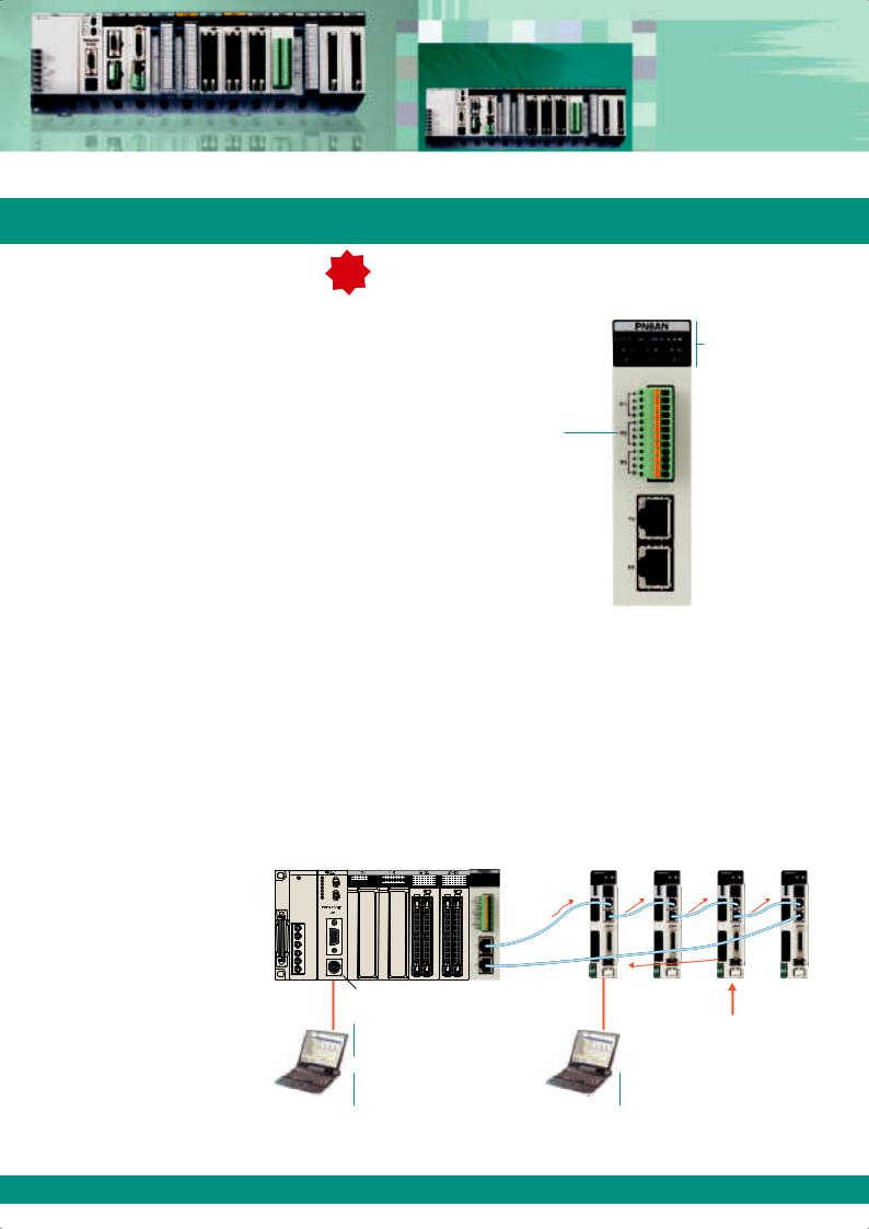
"RTEX" positioning units |
NEW! |
|
Compatible with Realtime Express MINAS A4N* network servo systems.
Facilitate multi-axis high precision positioning
High-accuracy multi-axis positioning control achieved by high-speed 100Mbps communication.
Compatible with commercially available LAN cables, significantly reducing wiring costs.
Two-axis unit available in addition to the fourand eight-axis units.
Data from a maximum of 600 points can be registered for each axis.
Three-axis helical interpolation supported in addition
to two-axis linear and two-axis circular interpolation functions.
Dedicated tool software "Configurator PM" supports operations from setup through startup and monitoring.
Equipped with a manual pulser input terminal, allowing for fine teaching.
*Realtime Express and MINAS A4N are a trademark and a product name of Matsushita Electric Industrial Co., Ltd.
High-speed 100Mbps communications
Monitoring LEDs
• Status indicator
• Link status
• Error indicator
• Pulser input status
Pulser input terminal
Network |
|
2 axes: FP2-PN2AN |
|
(transmission) port |
|||
|
|||
|
|
4 axes: FP2-PN4AN |
|
Network |
|
|
|
(reception) port |
8 axes: FP2-PN8AN |
||
|
|
||
Controls up to 256 axes, adequately supporting large-scale equipment control
Up to 32 eight-axis units can be connected and up to 256 axes controlled (when using FP2SH with H type backplane).
Selectable among two, four, and eight-axis types to flexibly support control system configurations of a few or multiple axes.
Use in combination with the ultra-high speed and large capacity FP2SH CPU unit (20k steps/1ms (measured by our company), program capacity of 120k steps) adequately supports the control of large-scale equipment.
System configuration:
Maximum number of connectable |
One positioning unit can control two to |
positioning units "RTEX" |
eight axes (depending on the type). |
FP2: 16 units FP2SH: 32 units |
Servo amplifier: MINAS A4N manufactured by |
|
Matsushita Electric Industrial Co., Ltd. |
|
Commercially |
|
TOOL port of CPU unit |
available LAN |
|
cable |
||
|
||
|
(Ethernet category 5e |
|
Dedicated tool software for |
shielded type) |
|
positioning units "RTEX" |
|
|
Configurator PM |
|
|
Programming tools |
|
|
Control FPWIN GR |
|
|
Control FPWIN Pro |
|
I/O signals of home position proximity sensors, limit sensors, etc. are sent to A4N
Dedicated tool software for MINAS manufactured by Matsushita Electric Industrial Co., Ltd.
Panaterm
Contact for inquiries about MINAS AC servomotor series: Panasonic Electric Works Europe AG Telephone: +49 (0) 8024-648-0, Fax: +49 (0) 8024-648-111, www.panasonic-electric-works.com
08/2007
Positioning
High-Speed, High-Precision Positioning
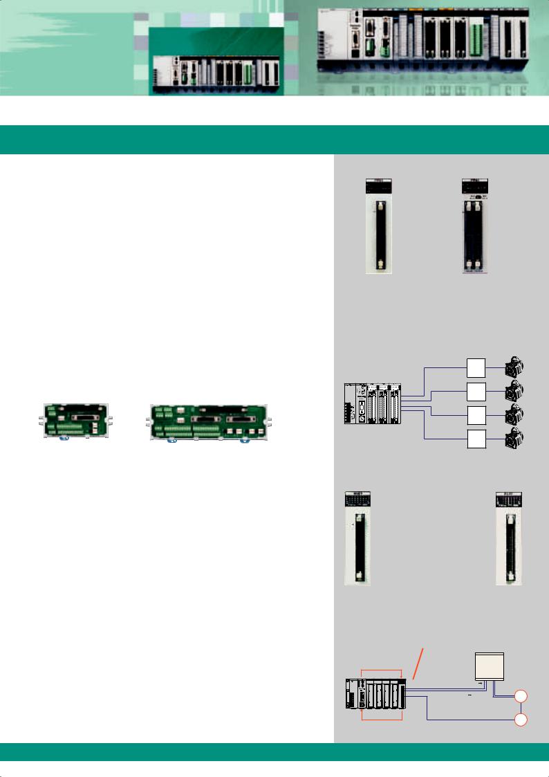
Positioning units
High-speed, high-accuracy pulse output type positioning unit. Speed command: 4Mpps, Startup time: 0.005ms
Support pulse-input type stepping motors, and servomotors. The speed command range is up to 4Mpps, allowing for high-speed and high-accuracy positioning. The startup time is as high as 0.005ms, allowing for a reduction of the tact time. (Startup time: Time between reception of a command from a CPU unit and pulse output from a positioning unit.)
The feedback pulse count function counts output pulses from encoders or other devices.
The jog positioning function widens the supported application range.
The four types of S-curve acceleration/deceleration control allow for smooth startup and stoppage.
Program libraries for linear interpolation and other operations are available.
Function "Libraries for FPWIN Pro" can be downloaded from our Website: www.panasonic-electric-works.com
Motor Driver I/F Terminal II is available for connection with MINAS AC servo series.
For 1 axis (AFP8503) |
For 2 axes (AFP8504) |
High-speed counter units and pulse I/O units
Interrupt, counting, pulse output, and PWM output functions are integrated in a single unit
Equipped with four channels of a maximum of 200kHz high-speed counter inputs, allowing for fine control.
Equipped with eight user-allocatable outputs for the four high-speed counter channels. The number of counter stages can be changed.
Interrupt function can start interrupt program when the time specified elapses or via external signal.
Control up to 100kpps pulse output and up to 30kpps PWM output.
A single module has high-speed counter, interrupt, general I/O, pulse output*, PWM output* functions, allowing for highly efficient system configuration.
* Only available with the pulse I/O units.
08/2007
Positioning unit (2 axes) |
Positioning unit (4 axes) |
FP2-PP21 FP2-PP22 |
FP2-PP41 FP2-PP42 |
Configuration
One unit can control up to 4 axes.
Motor |
driver |
Motor
driver
Motor |
driver |
Motor
driver
Stepping motor
Servomotor
Pulse I/O units
FP2-PXYT(NPN)
FP2-PXYP(PNP)
High-speed counter units
FP2-HSCT(NPN)
FP2-HSCP(PNP)
Configuration
Counts RPM based on the encoder output, compares the count with the preset RPM, and instructs the inver ter to adjust the speed or stop operation.
Set conditions with the |
|
|
F151 high-level instruction |
|
Inverter |
|
|
|
|
C=P Speed adjustment input |
|
|
C>P Stoppage |
M |
|
input |
|
|
|
Input the encoder output into the
 phase input mode.
E
Read data with the F150 high-level instruction
Analog Control
Accurate Process Control
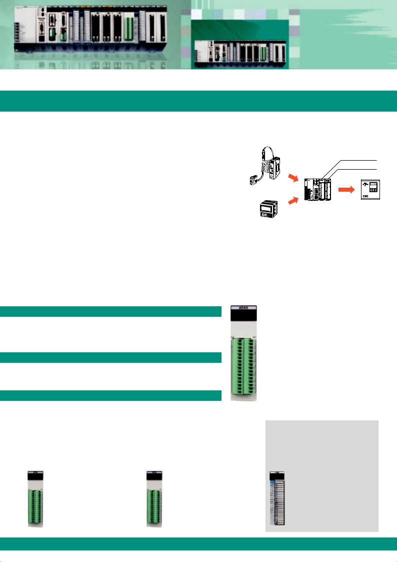
Analog control
Multi-range control of a variety of equipment is possible. The units can be directly connected with thermocouples and resistance temperature detectors
Support voltage/current/temperature sensor ranges
The analog input unit supports voltage, current, and temperature sensors. The analog output unit supports voltage or current output.
Different voltage/current ranges can be controlled concurrently.
Equipped with multiple channels
The input unit has eight channels, and the output unit has four. Space-saving multiple-channel control is possible.
High-speed conversion at 500ms by each channel
The speed of voltage and current input/output conversion can reach as high as 500ms.
I/O refresh system
Since input/output data is allocated to the I/O memory, complicated programming is not necessary.
Configuration
|
|
|
|
|
|
|
|
|
|
Analog input unit |
|
|
|
Current input |
|
|
|
|
|
Analog output unit |
|
|
|
|
|
|
|
|
|
|
||
|
|
|
|
|
|
|
|
|
|
|
|
|
|
|
|
|
|
|
|
|
|
|
|
|
|
|
|
|
|
|
|
|
|
|
|
|
|
|
|
|
|
|
|
|
|
|
|
|
|
|
|
|
|
|
|
|
|
|
|
|
|
|
|
|
|
Laser analog sensor
|
Voltage |
Inverter |
Current input |
output |
|
(speed command) |
||
Pressure sensor
Analog input units
Three types of analog input units are available to meet a wide variety of customer needs.
High-speed, high-accuracy, multiple-input unit with 8 isolated channels
Industry‘s fastest level
High-speed achieved by highly reliable isolation among channels |
|
Temperature conversion: |
20ms/ch |
Voltage conversion: |
5ms/ch |
(Without insulation setting: |
500ms/ch) |
Industry‘s top level |
|
|
High-accuracy conversion |
|
|
Voltage: ±0.1% (25°C) |
|
|
Temperature: ±0.3% (0 to 55°C) |
|
|
Multiple inputs |
|
|
A single unit supports inputs of |
FP2-AD8X |
|
thermocouple, RTD, and voltage data*1. |
||
|
For users who require faster and more accurate temperature control.
For users who require multiple isolated input channels or who want to reduce the cost per channel.
For users who want to input temperature and voltage (current) data through a single unit.
*1: Current inputs can be converted into voltage inputs by attaching the supplied external resistor to the input terminal section.
|
|
|
|
Analog output unit |
8 inputs unit solely for |
8 low costs inputs solely |
Supports multiple channels. |
||
RTDs (Pt100/Pt1000) |
for voltage/current data |
(Four channels per unit). |
||
|
|
|
|
|
High-speed, high-accuracy |
|
High-speed, high-accuracy |
|
High-speed, high-accuracy |
|
|
|
|
|
Conversion speed: 20ms/ch Conversion accuracy: ±0.3%
(0 to 55°C)
For users who input RTD data only and require more affordable type.
Low cost unit for input of voltage/ current data that indicates mea surements of pressure, flow rate, fluid volume, speed, etc.
Number of outputs: 4 Conversion speed: 500ms/ch Overall accuracy: ±1.0% FS
or less
(0 to 55°C)
FP2-RTD |
FP2-AD8VI |
FP2-DA4 |
08/2007
Networking
Connect all PLCs with Each Other
Support a wide variety of networks, such as open networks, PLC links, remote I/O systems, and S-LINK
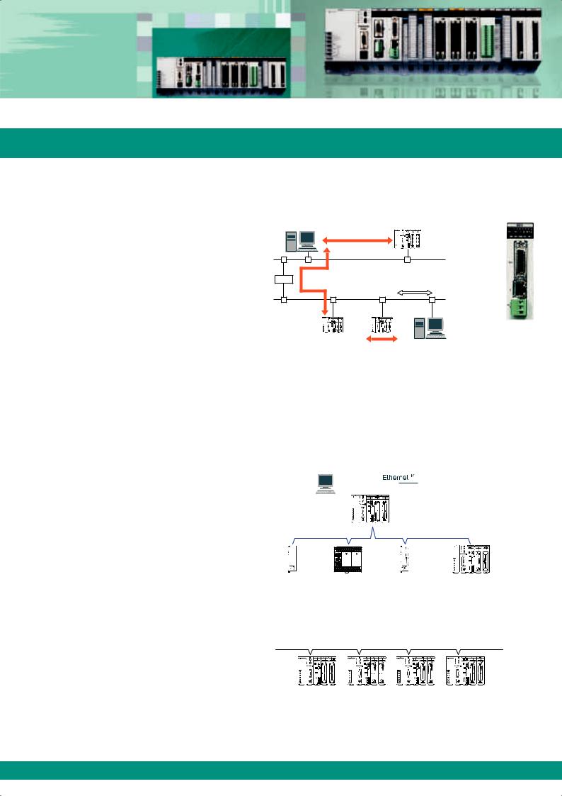
Open network
Ethernet
Supports three communication interfaces: 100BASE-TX, 10BASE-T, and 10BASE5.
Supports TCP/IP and UDP/IP.
Communication among a maximum of eight connections is available.
Compatible with user-friendly MEWTOCOL.
Supports remote programming.
|
Computer link |
|
|
|
LAN |
Router |
Computer link |
Transparent communication function |
FP2-ET1
Data transfer function
PLC link
PLC link is a system that allows our PLCs to share contact data and word data without programming.
MEWNET-W0 mode
A PLC link of the compact high-performance PLC FPΣ (Sigma)* and FP-X* can be established by using a combination of the multicommunication unit and an RS485 communication block. This mode enables the efficient connection of FP2/FP2SH, FPΣ (Sigma) and FP-X units on a single network and contributes to significant cost reduction.
115.2kbps transmission speed.
Transfer of data of 64 points/128 words is possible.
Up to 16 units can be connected.
Extendable to 1,200m.
|
|
|
|
|
|
|
|
|
|
|
|
|
|
|
|
|
|
|
|
|
|
|
|
|
|
|
|
|
|
|
|
FP2/FP2SH |
|||
|
|
|
|
|
|
|
|
|
|
|
|
|
|
||||
|
|
|
|
|
|
|
|
|
|
|
|
|
|
||||
|
|
|
|
|
|
|
|
|
|
|
|||||||
PLC link |
|
|
|
|
RS485 115.2kbps |
||||||||||||
(MEWNET-W0) |
|
|
|
|
Max. 16 stations/1,200m |
||||||||||||
|
|
|
|
|
|
|
|
|
|
|
|
|
|
|
|
|
|
|
|
|
|
|
|
|
|
|
|
|
|
|
|
|
|
|
|
FPΣ (Sigma) |
FP-X |
FPΣ (Sigma) |
FP2/FP2SH |
*Each FPΣ (Sigma) unit also requires an RS485 cassette (FPG-COM3 or FPG-COM4) to be attached.
*Each FP-X unit requires that an AFPX-COM3 or AFPX-COM4 communication cassette is attached.
MEWNET-W2 mode
Large capacity PLC links can be established by using twisted-pair cables and multi-wire link units.
500kbps transmission speed.
Transfer of data of 4096 points/4096 words is possible.
Up to 32 units can be connected.
Extendable to 1,200m
FP2 |
FP2 |
FP2 |
FP2 |
multi-wire |
multi-wire |
multi-wire |
multi-wire |
link unit |
link unit |
link unit |
link unit |
08/2007 |
|
Flexible Network Slave Unit
Continuous Communication in Industrial Applications
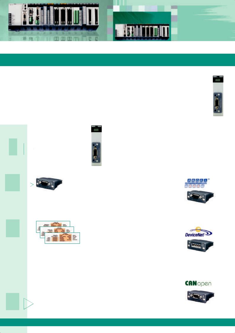
The Flexible Network Slave (FNS) unit is a powerful, modular network unit used together with the programmable controllers FP and FP SH. By exchanging compact network blocks, you can connect to various networking systems without having to modify your entire hardware platform. The blocks are available for three bus systems: PROFIBUS, DeviceNet and CANopen. Others are planned for the future.
FP -FNS
|
|
|
|
4 simple steps to |
1 |
|
|
|
setup your network |
|
|
|
Install the FP FNS expansion |
|
|
|
|
module on the backplane of your |
|
|
|
|||
|
|
|
||
|
|
|
FP system. The number of units |
|
|
|
|
is restricted by the size of the FP |
|
|
|
|
||
|
|
|||
|
|
|
|
backplane. |
Advantages:
Wide range of connectivity solutions.
One PLC hardware platform for several bus systems.
Fast reaction to new market networking trends possible with existing units: no additional hardware development needed: you need only exchange the network block.
Extremely compact.
2 

Various types of plug-in network blocks can be mounted in the device at any phase between manufacturer and end customer without having to worry about special protective provisions.
3 

For each network type, ready-made function libraries for FPWIN Pro are available free of charge from the Panasonic Electric Works Europe AG Website (www.panasonic-electric-works.com)
These libraries drastically shorten the time needed to develop your applications, and consequently save valuable human resource costs. They also include a complete online help file and programming examples.
Download the GSD or EDS files with the descrip- 4  tion of the device from the Panasonic Electric
Works Europe AG Website.
The master unit requires these files to recognize the slave device characteristics.
PROFIBUS:
Automatic baud rate detection.
Transmission speed of 9.6kbps to 1 Mbps.
Max. link area of 6 words (inputs and outputs).
Interface: DB9F (9-pin Sub-D female).
PROFIBUS Plug-in module AFPN-AB6 00
DeviceNet:
Automatic baud rate detection.
Transmission speed of 1 5kbps to 500kbps.
Max. link area of 1 8 words in each direction.
Interface: 5-pin terminal block.
DeviceNet Plug-in module AFPN-AB6 01
CANopen:
Automatic baud rate detection.
Transmission speed of 10kbps to 1Mbps.
Max. link area of 1 8 words (for TPDOs and RPDOs).
Interface: 9-pin Sub-D mode
CANopen Plug-in module AFPN-AB6 18
8 |
08/2007 |
FP Web-Server
Program/Operate the PLC using an Ethernet Network
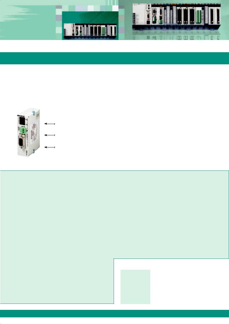
The multifunctional FP Web-Server provides users with the option of connecting any FP Series PLC to the Internet/Intranet for bi-directional communication via Ethernet. No changes to the PLC programs are necessary. Simply assign an IP address to the FP Web-Server and connect the PLC to the FP Web-Server via the serial RS232C interface. A standard browser, e.g. MS Internet Explorer, can be used for access at the PC. The Windows-based program FP Web Configurator Tool helps you easily set up and configure the FP Web-Server.
The FP Web-Server´s 3 interfaces
100Base-TX / 10Base-T (RJ45, twisted pair)
– connects to the Ethernet at 100Mbit/s
RS232C (screw terminal)
– connects to the PLC at 1200 to 115.2kbit/s
RS232C (SUB-D 9 male)
– connects to a modem
FP Web-Server advantages
Uses existing Intranet, saves wiring.
Uses standard browser, saves Scada software.
Remote control.
Remote monitoring.
Remote programming.
Alarm information via e-mail.
FPWEB2
Highlights
Web-Server:
PLC data presented as HTML (or XML) pages
Access via standard Internet browser.
PLC data handling via HTML and Java Applet.
Optional: Password protection, IP lock security.
RS232C device server:
Ethernet <-> RS232C conversion (MEWTOCOL).
Transparent RS232C data tunneling via Ethernet.
Programming and visualization via TCP or UDP.
Modem dial-out / Internet system:
FP Web-Server can dial-out to the Internet.
Various Internet / GPRS system solutions.
Network time server synchronization:
PLC real-time clock update via NTP server.
PLC can send e-mails.
E-mail via LAN e-mail server or Internet dial-up.
PLC-defined or pre-stored e-mail text.
PLC data array as attachment to an e-mail.
Modem dial-in / Ethernet gateway:
FP Web-Server can be dialed up via modem.
One remote gateway for multiple FP Web-Servers.
Modbus-TCP protocol:
Communication via standard industrial Ethernet protocol (server and client).
Gateway for Modbus-RTU units (master and slave).
IEC 60870-5-101 and IEC 60870-5-104 protocol:
Communication via RS232C, RS485 adapter, multipoint modem, dial-up modem, Ethernet.
08/2007
|
Specifications |
|
Current consumption |
65mA |
|
Operating voltage |
24VDC (10.8-26.4VDC) |
|
Communication interfaces |
RS232C for connection to a PLC, RS232C for modem |
|
connection, 100Base-TX/10Base-T, Ethernet |
||
|
||
Communication protocol |
MEWTOCOL, DNS, HTTP, SMTP, FTP TELNET, TCP/IP, UDP/ |
|
IP, PPP, SNTP, Modbus |
||
|
||
Safety |
Passwords, IP lock |
|
Ambient temp. |
0°C to 55°C |
|
Storage temp. |
-20°C to +70°C |
|
Dimensions |
25W x 90H x 60D (mm) |
|
Weight |
0.11kg |
 Loading...