


 Loading...
Packard Bell EasyNote LJ65
Service Guide
Service guide files and updates are available on the ACER/CSD web; for more information, please refer to http://csd.acer.com.tw
PRINTED IN TAIWAN

Revision History
Please refer to the table below for the updates made to this service guide.
Date |
Chapter |
Updates |
|
|
|
|
|
|
|
|
|
|
|
|
II

Copyright
Copyright © 2009 by Acer Incorporated. All rights reserved. No part of this publication may be reproduced, transmitted, transcribed, stored in a retrieval system, or translated into any language or computer language, in any form or by any means, electronic, mechanical, magnetic, optical, chemical, manual or otherwise, without the prior written permission of Acer Incorporated.
Disclaimer
The information in this guide is subject to change without notice.
Acer Incorporated makes no representations or warranties, either expressed or implied, with respect to the contents hereof and specifically disclaims any warranties of merchantability or fitness for any particular purpose. Any Acer Incorporated software described in this manual is sold or licensed "as is". Should the programs prove defective following their purchase, the buyer (and not Acer Incorporated, its distributor, or its dealer) assumes the entire cost of all necessary servicing, repair, and any incidental or consequential damages resulting from any defect in the software.
Acer is a registered trademark of Acer Corporation. Intel is a registered trademark of Intel Corporation.
Pentium and Pentium II/III are trademarks of Intel Corporation.
Other brand and product names are trademarks and/or registered trademarks of their respective holders.
III

Conventions
The following conventions are used in this manual:
SCREEN MESSAGES |
Denotes actual messages that appear |
|
on screen. |
|
|
NOTE |
Gives bits and pieces of additional |
|
information related to the current |
|
topic. |
|
|
WARNING |
Alerts you to any damage that might |
|
result from doing or not doing specific |
|
actions. |
|
|
CAUTION |
Gives precautionary measures to |
|
avoid possible hardware or software |
|
problems. |
|
|
IMPORTANT |
Reminds you to do specific actions |
|
relevant to the accomplishment of |
|
procedures. |
|
|
IV

Preface
Before using this information and the product it supports, please read the following general information.
1.This Service Guide provides you with all technical information relating to the BASIC CONFIGURATION decided for Acer's "global" product offering. To better fit local market requirements and enhance product competitiveness, your regional office MAY have decided to extend the functionality of a machine (e.g. add-on card, modem, or extra memory capability). These LOCALIZED FEATURES will NOT be covered in this generic service guide. In such cases, please contact your regional offices or the responsible personnel/channel to provide you with further technical details.
2.Please note WHEN ORDERING FRU PARTS, that you should check the most up-to-date information available on your regional web or channel. If, for whatever reason, a part number change is made, it will not be noted in the printed Service Guide. For ACER-AUTHORIZED SERVICE PROVIDERS, your Acer office may have a DIFFERENT part number code to those given in the FRU list of this printed Service Guide. You MUST use the list provided by your regional Acer office to order FRU parts for repair and service of customer machines.
V

VI

Table of Contents
System Specifications |
1 |
Features . . . . . . . . . . . . . . . . . . . . . . . . . . . . . . . . . . . . . . . . . . . . . . . . . . . . . . . . . . . .1 System Block Diagram . . . . . . . . . . . . . . . . . . . . . . . . . . . . . . . . . . . . . . . . . . . . . . . . .4 Your Notebook tour . . . . . . . . . . . . . . . . . . . . . . . . . . . . . . . . . . . . . . . . . . . . . . . . . . . .5 Front View . . . . . . . . . . . . . . . . . . . . . . . . . . . . . . . . . . . . . . . . . . . . . . . . . . . . . . .5 Left View . . . . . . . . . . . . . . . . . . . . . . . . . . . . . . . . . . . . . . . . . . . . . . . . . . . . . . . .6 Right View . . . . . . . . . . . . . . . . . . . . . . . . . . . . . . . . . . . . . . . . . . . . . . . . . . . . . . .7 Rear View . . . . . . . . . . . . . . . . . . . . . . . . . . . . . . . . . . . . . . . . . . . . . . . . . . . . . . .7 Bottom View . . . . . . . . . . . . . . . . . . . . . . . . . . . . . . . . . . . . . . . . . . . . . . . . . . . . .8 Keyboard Area (selected models) . . . . . . . . . . . . . . . . . . . . . . . . . . . . . . . . . . . . .9 LCD Panel . . . . . . . . . . . . . . . . . . . . . . . . . . . . . . . . . . . . . . . . . . . . . . . . . . . . . .10 Status Indicators . . . . . . . . . . . . . . . . . . . . . . . . . . . . . . . . . . . . . . . . . . . . . . . . .11 TouchPad Basics . . . . . . . . . . . . . . . . . . . . . . . . . . . . . . . . . . . . . . . . . . . . . . . .12 Using the Keyboard . . . . . . . . . . . . . . . . . . . . . . . . . . . . . . . . . . . . . . . . . . . . . . . . . .13 Key Types . . . . . . . . . . . . . . . . . . . . . . . . . . . . . . . . . . . . . . . . . . . . . . . . . . . . . .13 Windows Keys . . . . . . . . . . . . . . . . . . . . . . . . . . . . . . . . . . . . . . . . . . . . . . . . . .14 System Keys . . . . . . . . . . . . . . . . . . . . . . . . . . . . . . . . . . . . . . . . . . . . . . . . . . . .15 Using the System Utilities . . . . . . . . . . . . . . . . . . . . . . . . . . . . . . . . . . . . . . . . . . . . . .16 Acer GridVista (dual-display compatible) . . . . . . . . . . . . . . . . . . . . . . . . . . . . . .16 Hardware Specifications and Configurations . . . . . . . . . . . . . . . . . . . . . . . . . . . . . . .17
System Utilities |
27 |
BIOS Setup Utility . . . . . . . . . . . . . . . . . . . . . . . . . . . . . . . . . . . . . . . . . . . . . . . . . . . .27
Navigating the BIOS Utility . . . . . . . . . . . . . . . . . . . . . . . . . . . . . . . . . . . . . . . . .27
Information . . . . . . . . . . . . . . . . . . . . . . . . . . . . . . . . . . . . . . . . . . . . . . . . . . . . .28
Main . . . . . . . . . . . . . . . . . . . . . . . . . . . . . . . . . . . . . . . . . . . . . . . . . . . . . . . . . .29
Advanced . . . . . . . . . . . . . . . . . . . . . . . . . . . . . . . . . . . . . . . . . . . . . . . . . . . . . .30
Security . . . . . . . . . . . . . . . . . . . . . . . . . . . . . . . . . . . . . . . . . . . . . . . . . . . . . . . .32
Power . . . . . . . . . . . . . . . . . . . . . . . . . . . . . . . . . . . . . . . . . . . . . . . . . . . . . . . . .35
Boot . . . . . . . . . . . . . . . . . . . . . . . . . . . . . . . . . . . . . . . . . . . . . . . . . . . . . . . . . . .37
Exit . . . . . . . . . . . . . . . . . . . . . . . . . . . . . . . . . . . . . . . . . . . . . . . . . . . . . . . . . . .38
BIOS Flash Utilities . . . . . . . . . . . . . . . . . . . . . . . . . . . . . . . . . . . . . . . . . . . . . . . . . . .39
DOS Flash Utility . . . . . . . . . . . . . . . . . . . . . . . . . . . . . . . . . . . . . . . . . . . . . . . . .40
WinFlash Utility . . . . . . . . . . . . . . . . . . . . . . . . . . . . . . . . . . . . . . . . . . . . . . . . . .42
Remove HDD/BIOS Password Utilities . . . . . . . . . . . . . . . . . . . . . . . . . . . . . . . . . . . .43
Machine Disassembly and Replacement |
49 |
Disassembly Requirements . . . . . . . . . . . . . . . . . . . . . . . . . . . . . . . . . . . . . . . . . . . |
.49 |
General Information . . . . . . . . . . . . . . . . . . . . . . . . . . . . . . . . . . . . . . . . . . . . . . . . . |
.50 |
Pre-disassembly Instructions . . . . . . . . . . . . . . . . . . . . . . . . . . . . . . . . . . . . . . |
.50 |
Disassembly Process . . . . . . . . . . . . . . . . . . . . . . . . . . . . . . . . . . . . . . . . . . . . . |
50 |
External Module Disassembly Process . . . . . . . . . . . . . . . . . . . . . . . . . . . . . . . . . . . |
51 |
External Modules Disassembly Flowchart . . . . . . . . . . . . . . . . . . . . . . . . . . . . . |
51 |
Removing the Battery Pack . . . . . . . . . . . . . . . . . . . . . . . . . . . . . . . . . . . . . . . . |
52 |
Removing the SD dummy card . . . . . . . . . . . . . . . . . . . . . . . . . . . . . . . . . . . . . . |
53 |
Removing the Lower Covers . . . . . . . . . . . . . . . . . . . . . . . . . . . . . . . . . . . . . . . . |
54 |
Removing the Optical Drive Module . . . . . . . . . . . . . . . . . . . . . . . . . . . . . . . . . . |
55 |
Removing the DIMM Modules . . . . . . . . . . . . . . . . . . . . . . . . . . . . . . . . . . . . . . . |
57 |
Removing the WLAN Module . . . . . . . . . . . . . . . . . . . . . . . . . . . . . . . . . . . . . . . |
58 |
Removing the Primary HDD Module . . . . . . . . . . . . . . . . . . . . . . . . . . . . . . . . . . |
60 |
Removing the Secondary HDD Module . . . . . . . . . . . . . . . . . . . . . . . . . . . . . . . |
62 |
Main Unit Disassembly Process . . . . . . . . . . . . . . . . . . . . . . . . . . . . . . . . . . . . . . . . . |
64 |
Main Unit Disassembly Flowchart . . . . . . . . . . . . . . . . . . . . . . . . . . . . . . . . . . . . |
64 |
Removing the Switch Cover . . . . . . . . . . . . . . . . . . . . . . . . . . . . . . . . . . . . . . . . |
65 |
VII

Table of Contents |
|
Removing the Media Board . . . . . . . . . . . . . . . . . . . . . . . . . . . . . . . . . . . . . . . |
.68 |
Removing the Keyboard . . . . . . . . . . . . . . . . . . . . . . . . . . . . . . . . . . . . . . . . . . |
.69 |
Removing the LCD Module . . . . . . . . . . . . . . . . . . . . . . . . . . . . . . . . . . . . . . . . |
.71 |
Removing the Upper Cover . . . . . . . . . . . . . . . . . . . . . . . . . . . . . . . . . . . . . . . |
.76 |
Removing the TouchPad Bracket . . . . . . . . . . . . . . . . . . . . . . . . . . . . . . . . . . . |
.80 |
Removing the Media Board FFC . . . . . . . . . . . . . . . . . . . . . . . . . . . . . . . . . . . |
.81 |
Removing the LED Board . . . . . . . . . . . . . . . . . . . . . . . . . . . . . . . . . . . . . . . . . |
.82 |
Removing the Speaker Module . . . . . . . . . . . . . . . . . . . . . . . . . . . . . . . . . . . . . |
.83 |
Removing the RTC Battery . . . . . . . . . . . . . . . . . . . . . . . . . . . . . . . . . . . . . . . . |
.85 |
Removing the Modem Board . . . . . . . . . . . . . . . . . . . . . . . . . . . . . . . . . . . . . . |
.86 |
Removing the USB Board . . . . . . . . . . . . . . . . . . . . . . . . . . . . . . . . . . . . . . . . . |
.88 |
Removing the Mainboard . . . . . . . . . . . . . . . . . . . . . . . . . . . . . . . . . . . . . . . . . |
.90 |
Removing the RJ-11 Jack . . . . . . . . . . . . . . . . . . . . . . . . . . . . . . . . . . . . . . . . . |
.91 |
Removing the CPU Fan . . . . . . . . . . . . . . . . . . . . . . . . . . . . . . . . . . . . . . . . . . |
.93 |
Removing the Thermal Module . . . . . . . . . . . . . . . . . . . . . . . . . . . . . . . . . . . . . |
.94 |
Removing the CPU . . . . . . . . . . . . . . . . . . . . . . . . . . . . . . . . . . . . . . . . . . . . . . |
.95 |
LCD Module Disassembly Process . . . . . . . . . . . . . . . . . . . . . . . . . . . . . . . . . . . . . |
.96 |
LCD Module Disassembly Flowchart . . . . . . . . . . . . . . . . . . . . . . . . . . . . . . . . |
.96 |
Removing the LCD Bezel . . . . . . . . . . . . . . . . . . . . . . . . . . . . . . . . . . . . . . . . . |
.97 |
Removing the Camera Module . . . . . . . . . . . . . . . . . . . . . . . . . . . . . . . . . . . . . |
.98 |
Removing the LCD Panel . . . . . . . . . . . . . . . . . . . . . . . . . . . . . . . . . . . . . . . . . |
.99 |
Removing the Power Board . . . . . . . . . . . . . . . . . . . . . . . . . . . . . . . . . . . . . . . |
100 |
Removing the LCD Brackets and FPC Cable . . . . . . . . . . . . . . . . . . . . . . . . . . |
101 |
Removing the Microphone Module . . . . . . . . . . . . . . . . . . . . . . . . . . . . . . . . . . |
103 |
Removing the Antennas . . . . . . . . . . . . . . . . . . . . . . . . . . . . . . . . . . . . . . . . . . |
104 |
LCD Module Reassembly Procedure . . . . . . . . . . . . . . . . . . . . . . . . . . . . . . . . . . . . |
106 |
Replacing the Antennas, Power Board, and MIC . . . . . . . . . . . . . . . . . . . . . . . |
106 |
Replacing the LCD Panel . . . . . . . . . . . . . . . . . . . . . . . . . . . . . . . . . . . . . . . . . |
109 |
Replacing the Camera Module . . . . . . . . . . . . . . . . . . . . . . . . . . . . . . . . . . . . . |
111 |
Replacing the LCD Bezel . . . . . . . . . . . . . . . . . . . . . . . . . . . . . . . . . . . . . . . . . |
112 |
Main Module Reassembly Procedure . . . . . . . . . . . . . . . . . . . . . . . . . . . . . . . . |
114 |
Replacing the CPU . . . . . . . . . . . . . . . . . . . . . . . . . . . . . . . . . . . . . . . . . . . . . . |
114 |
Replacing the Thermal Module . . . . . . . . . . . . . . . . . . . . . . . . . . . . . . . . . . . . . |
114 |
Replacing the CPU Fan . . . . . . . . . . . . . . . . . . . . . . . . . . . . . . . . . . . . . . . . . . |
115 |
Replacing the RJ-11 Jack . . . . . . . . . . . . . . . . . . . . . . . . . . . . . . . . . . . . . . . . . |
116 |
Replacing the Mainboard . . . . . . . . . . . . . . . . . . . . . . . . . . . . . . . . . . . . . . . . . |
117 |
Replacing the USB Board . . . . . . . . . . . . . . . . . . . . . . . . . . . . . . . . . . . . . . . . . |
118 |
Replacing the Modem Board . . . . . . . . . . . . . . . . . . . . . . . . . . . . . . . . . . . . . . |
119 |
Replacing the Speaker Module . . . . . . . . . . . . . . . . . . . . . . . . . . . . . . . . . . . . . |
120 |
Replacing the LED Board . . . . . . . . . . . . . . . . . . . . . . . . . . . . . . . . . . . . . . . . . |
121 |
Replacing the Media Board FFC . . . . . . . . . . . . . . . . . . . . . . . . . . . . . . . . . . . . |
121 |
Replacing the TouchPad Bracket . . . . . . . . . . . . . . . . . . . . . . . . . . . . . . . . . . . |
122 |
Replacing the Upper Cover . . . . . . . . . . . . . . . . . . . . . . . . . . . . . . . . . . . . . . . . |
122 |
Replacing the LCD Module . . . . . . . . . . . . . . . . . . . . . . . . . . . . . . . . . . . . . . . . |
126 |
Replacing the Keyboard . . . . . . . . . . . . . . . . . . . . . . . . . . . . . . . . . . . . . . . . . . |
129 |
Replacing the Media Board . . . . . . . . . . . . . . . . . . . . . . . . . . . . . . . . . . . . . . . . |
130 |
Replacing the Switch Cover . . . . . . . . . . . . . . . . . . . . . . . . . . . . . . . . . . . . . . . |
131 |
Replacing the Hard Disk Drive Modules . . . . . . . . . . . . . . . . . . . . . . . . . . . . . . |
133 |
Replacing the WLAN Module . . . . . . . . . . . . . . . . . . . . . . . . . . . . . . . . . . . . . . |
134 |
Replacing the DIMM Modules . . . . . . . . . . . . . . . . . . . . . . . . . . . . . . . . . . . . . . |
134 |
Replacing the ODD Module . . . . . . . . . . . . . . . . . . . . . . . . . . . . . . . . . . . . . . . |
135 |
Replacing the Lower Covers . . . . . . . . . . . . . . . . . . . . . . . . . . . . . . . . . . . . . . . |
135 |
Replacing the SD Dummy Card . . . . . . . . . . . . . . . . . . . . . . . . . . . . . . . . . . . . |
137 |
Replacing the Battery . . . . . . . . . . . . . . . . . . . . . . . . . . . . . . . . . . . . . . . . . . . . |
137 |
VIII

Table of Contents
Troubleshooting |
139 |
Common Problems . . . . . . . . . . . . . . . . . . . . . . . . . . . . . . . . . . . . . . . . . . . . . . . . . .139 Power On Issue . . . . . . . . . . . . . . . . . . . . . . . . . . . . . . . . . . . . . . . . . . . . . . . .140 No Display Issue . . . . . . . . . . . . . . . . . . . . . . . . . . . . . . . . . . . . . . . . . . . . . . . .141 Random Loss of BIOS Settings . . . . . . . . . . . . . . . . . . . . . . . . . . . . . . . . . . . .142 LCD Failure . . . . . . . . . . . . . . . . . . . . . . . . . . . . . . . . . . . . . . . . . . . . . . . . . . . .143 Built-In Keyboard Failure . . . . . . . . . . . . . . . . . . . . . . . . . . . . . . . . . . . . . . . . .143 TouchPad Failure . . . . . . . . . . . . . . . . . . . . . . . . . . . . . . . . . . . . . . . . . . . . . . .144 Internal Speaker Failure . . . . . . . . . . . . . . . . . . . . . . . . . . . . . . . . . . . . . . . . . .145 Internal Microphone Failure . . . . . . . . . . . . . . . . . . . . . . . . . . . . . . . . . . . . . . .147 HDD Not Operating Correctly . . . . . . . . . . . . . . . . . . . . . . . . . . . . . . . . . . . . . .148 ODD Failure . . . . . . . . . . . . . . . . . . . . . . . . . . . . . . . . . . . . . . . . . . . . . . . . . . .149 USB (Right Side) Failure . . . . . . . . . . . . . . . . . . . . . . . . . . . . . . . . . . . . . . . . . .153 Wireless Function Failure . . . . . . . . . . . . . . . . . . . . . . . . . . . . . . . . . . . . . . . . .154 Bluetooth Function Test Failure . . . . . . . . . . . . . . . . . . . . . . . . . . . . . . . . . . . .155 Easy Button Failure . . . . . . . . . . . . . . . . . . . . . . . . . . . . . . . . . . . . . . . . . . . . . .156 Thermal Unit Failure . . . . . . . . . . . . . . . . . . . . . . . . . . . . . . . . . . . . . . . . . . . . .157 External Mouse Failure . . . . . . . . . . . . . . . . . . . . . . . . . . . . . . . . . . . . . . . . . . .157 Other Failures . . . . . . . . . . . . . . . . . . . . . . . . . . . . . . . . . . . . . . . . . . . . . . . . . .158
Motherboard CMOS Discharge . . . . . . . . . . . . . . . . . . . . . . . . . . . . . . . . . . . . . . . .159 Intermittent Problems . . . . . . . . . . . . . . . . . . . . . . . . . . . . . . . . . . . . . . . . . . . . . . . .159 Undetermined Problems . . . . . . . . . . . . . . . . . . . . . . . . . . . . . . . . . . . . . . . . . . . . . .159 Post Codes . . . . . . . . . . . . . . . . . . . . . . . . . . . . . . . . . . . . . . . . . . . . . . . . . . . . . . . .161 Chipset POST Codes . . . . . . . . . . . . . . . . . . . . . . . . . . . . . . . . . . . . . . . . . . . .161 Sec: . . . . . . . . . . . . . . . . . . . . . . . . . . . . . . . . . . . . . . . . . . . . . . . . . . . . . . . . . .161 Memory: . . . . . . . . . . . . . . . . . . . . . . . . . . . . . . . . . . . . . . . . . . . . . . . . . . . . . .161 BDS & Specific action: . . . . . . . . . . . . . . . . . . . . . . . . . . . . . . . . . . . . . . . . . . .162 Each PEIM entry point used in 80_PORT . . . . . . . . . . . . . . . . . . . . . . . . . . . . .164 Each Driver entry point used in 80_PORT . . . . . . . . . . . . . . . . . . . . . . . . . . . .164 Each SmmDriver entry point used in 80_PORT . . . . . . . . . . . . . . . . . . . . . . . .167
Jumper and Connector Locations |
169 |
Top View . . . . . . . . . . . . . . . . . . . . . . . . . . . . . . . . . . . . . . . . . . . . . . . . . . . . . |
.169 |
Bottom View . . . . . . . . . . . . . . . . . . . . . . . . . . . . . . . . . . . . . . . . . . . . . . . . . . |
.170 |
LS-5022P USB Board . . . . . . . . . . . . . . . . . . . . . . . . . . . . . . . . . . . . . . . . . . . |
.171 |
LS-5024P Cap Sensor Board . . . . . . . . . . . . . . . . . . . . . . . . . . . . . . . . . . . . . |
.171 |
LS-5026P LED Board . . . . . . . . . . . . . . . . . . . . . . . . . . . . . . . . . . . . . . . . . . . |
.171 |
LS-5027P SW Board . . . . . . . . . . . . . . . . . . . . . . . . . . . . . . . . . . . . . . . . . . . . |
.172 |
Clearing Password Check and BIOS Recovery . . . . . . . . . . . . . . . . . . . . . . . . . . . |
.173 |
Clearing Password Check . . . . . . . . . . . . . . . . . . . . . . . . . . . . . . . . . . . . . . . . |
.173 |
BIOS Recovery by Crisis Disk . . . . . . . . . . . . . . . . . . . . . . . . . . . . . . . . . . . . |
.174 |
FRU (Field Replaceable Unit) List |
175 |
Packard Bell EasyNote LJ65 Exploded Diagrams . . . . . . . . . . . . . . . . . . . . . . . . . .176
Main Assembly . . . . . . . . . . . . . . . . . . . . . . . . . . . . . . . . . . . . . . . . . . . . . . . . .176
Rear Assembly . . . . . . . . . . . . . . . . . . . . . . . . . . . . . . . . . . . . . . . . . . . . . . . . .177
LCD Assembly . . . . . . . . . . . . . . . . . . . . . . . . . . . . . . . . . . . . . . . . . . . . . . . . .178
Base Top Assembly . . . . . . . . . . . . . . . . . . . . . . . . . . . . . . . . . . . . . . . . . . . . .179
Packard Bell EasyNote LJ65 FRU List . . . . . . . . . . . . . . . . . . . . . . . . . . . . . . . . . . .180
Screw List . . . . . . . . . . . . . . . . . . . . . . . . . . . . . . . . . . . . . . . . . . . . . . . . . . . . .188
Model Definition and Configuration |
190 |
Packard Bell EasyNote LJ65 Series . . . . . . . . . . . . . . . . . . . . . . . . . . . . . . . . . . . . .190
IX

Table of Contents |
|
Test Compatible Components |
199 |
Microsoft® Windows® Vista Environment Test . . . . . . . . . . . . . . . . . . . . . . . . . . . |
.200 |
Online Support Information |
205 |
Index |
207 |
X
Chapter 1
System Specifications
Features
Below is a brief summary of the computer’s many features:
NOTE: Items marked with * denote only selected models.
Operating System
•Genuine Windows Vista® Home Premium
Platform
•Intel® Centrino® processor technology, featuring:
•Intel® Core™2 Duo processor T6400 (2 MB L2 cache, 2 GHz, 800 MHz FSB, 35 W), supporting Intel® 64 architecture
•Mobile Intel® PM45 Express Chipset
•Intel® Wireless WiFi Link 5100/5300 (dual-band quad-mode 802.11a/b/g/Draft-N) Wi-Fi CERTIFIED® wireless LAN card
System Memory
•Dual-channel DDR3 SDRAM support
•Up to 4 GB of DDR3 800 MHz memory, upgradeable to 8 GB using two soDIMM modules (for 64bit OS)
•Up to 2 GB of DDR3 800 MHz memory, upgradeable to 4 GB using two soDIMM modules (for 32bit OS)
Display
•17.3" HD 1600 x 900 pixel resolution, high-brightness (220-nit) Ultrabright™ TFT LCD, supporting simultaneous multi-window viewing
•16:9 aspect ratio
•8 ms response time
•60% color gamut
Graphics
•ATI Mobility Radeon™ HD 4570 with up to 2304 MB of HyperMemory™ (512 MB of dedicated DDR2 VRAM, up to 1792 MB of shared system memory), supporting Unified Video Decoder (UVD), OpenEXR High Dynamic-Range (HDR) technology, Shader Model 4.1, Microsoft® DirectX® 10.1
•Dual independent display support
•16.7 million colors
•MPEG-2/DVD decoding
•WMV9 (VC-1) and H.264 (AVC) decoding
Chapter 1 |
1 |

•HDMI™ (High-Definition Multimedia Interface) with HDCP (High-bandwidth Digital Content Protection) support
Storage subsystem
•160/250/320/500 GB hard disk drive
•Media card reader, supporting:
•Secure Digital™ (SD) Card, MultiMediaCard (MMC), Memory Stick™ (MS), Memory Stick PRO™ (MS PRO), xD-Picture Card™ (xD)
•Storage cards with adapter: miniSD™, microSD™, Reduced-Size Multimedia Card (RSMMC), Memory Stick Duo™, Memory Stick PRO Duo™
Optical Drive
•8X DVD-Super Multi double-layer drive:
•Read: 24X CD-ROM, 24X CD-R, 24X CD-RW, 8X DVD-ROM, 8X DVD-R, 8X DVD+R, 6X DVD-ROM DL (double-layer), 6X DVD-R DL (double-layer), 6X DVD+R DL (double-layer), 6X DVD-RW, 6X DVD+RW, 5X DVD-RAM
•Write: 24X CD-R, 16X CD-RW, 8X DVD-R, 8X DVD+R, 4X DVD-R DL (double-layer), 4X DVD+R DL (double-layer), 6X DVD-RW, 8X DVD+RW, 5X DVD-RAM
Audio
•Two built-in stereo speakers
•High-definition audio support
•S/PDIF (Sony/Philips Digital Interface) support for digital speakers
•Built-in microphone
•MS-Sound compatible
Dimensions and Weight
•412 x 280 x 38.6 mm (16.2 x 11.0 x 1.5 inches)
•3.3 kg (7.4 lbs.) with 6-cell battery pack
•3.4 kg (7.6 lbs.) with 8-cell battery pack
Communication
•WLAN: Intel® Wireless WiFi Link 5100/5300 (dual-band quad-mode 802.11a/b/g/Draft-N) Wi-Fi CERTIFIED® wireless LAN card
•WPAN1: Bluetooth® 2.1+EDR (Enhanced Data Rate)
•LAN: Gigabit Ethernet, Wake-on-LAN ready
Privacy control
•BIOS user, supervisor, HDD passwords
•Kensington lock slot
2 |
Chapter 1 |

Power subsystem
•ACPI 3.0 CPU power management standard: supports Standby and Hibernation power-saving modes
•4800 mAh 8-cell Li-ion battery pack with discrete graphics:
•3-hour, 20-minute battery life
•3-pin 90 W AC adapter
•4400 mAh 6-cell Li-ion battery pack with integrated graphics:
•3-hour, 10-minute battery life
•3-pin 65 W AC adapter
•ENERGY STAR® 5.0
Special keys and controls
•99-/100-/103-key keyboard
•Touchpad pointing device
•Nine function keys, four cursor keys, Windows® key, international language support
I/O interface
•Media card reader
•Four USB 2.0 ports
•HDMI™ port with HDCP support
•External display (VGA) port
•Headphone/speaker/line-out jack with S/PDIF support
•Microphone-in jack
•Ethernet (RJ-45) port
•DC-in jack for AC adapter
Environment
•Temperature:
•Operating: 5 °C to 35 °C
•Non-operating: -20 °C to 65 °C
•Humidity (non-condensing):
•Operating: 20% to 80%
•Non-operating: 20% to 80%
NOTE: Items marked with * denote only selected models.
Chapter 1 |
3 |

System Block Diagram
4 |
Chapter 1 |

Your Notebook tour
After knowing your computer features, let us show you around your new computer.
Front View
Ventilation fan
Component |
Icon |
Description |
|
|
|
Ventilation fan |
|
Helps cool internal components. |
|
|
Warning: Do not work with the notebook resting on your |
|
|
lap. If the air vents are blocked, the notebook may become |
|
|
hot enough to harm your skin. |
|
|
Caution: Do not block or insert objects into these slots. If |
|
|
these slots are blocked, your notebook may overheat |
|
|
resulting in unexpected shutdown or permanent damage to |
|
|
the notebook. |
|
|
Caution: Provide adequate space around your notebook |
|
|
so air vents are not obstructed. Do not use the notebook on |
|
|
a bed, sofa, rug, or other similar surface. |
|
|
|
Chapter 1 |
5 |
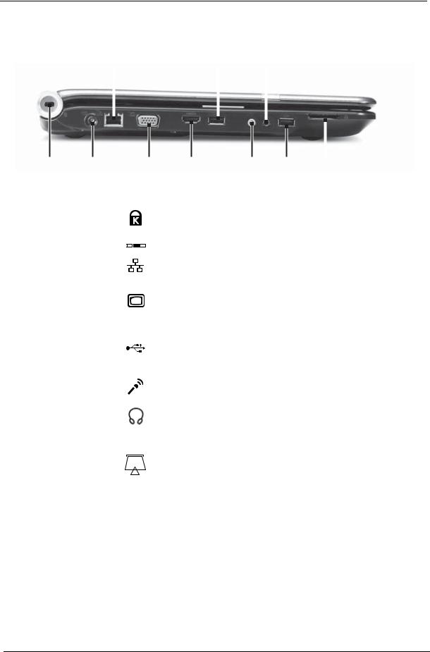
Left View
|
|
|
Ethernet |
|
USB |
Headphone |
|
|
|||||||||||||||
|
|
|
jack |
|
port |
jack |
|
|
|||||||||||||||
|
|
|
|
|
|
|
|
|
|
|
|
|
|
|
|
|
|
|
|
|
|
|
|
|
|
|
|
|
|
|
|
|
|
|
|
|
|
|
|
|
|
|
|
|
|
|
|
|
|
|
|
|
|
|
|
|
|
|
|
|
|
|
|
|
|
|
|
|
|
|
|
|
|
|
|
|
|
|
|
|
|
|
|
|
|
|
|
|
|
|
|
|
|
|
|
|
|
|
|
|
|
|
|
|
|
|
|
|
|
|
|
|
|
|
|
|
|
|
|
|
|
|
|
|
|
|
|
|
|
|
|
|
|
|
|
|
|
|
|
|
|
|
|
|
|
|
|
|
|
|
|
|
|
|
|
|
|
|
|
|
|
|
|
|
|
|
|
|
|
|
|
|
|
|
|
|
|
|
|
|
|
|
|
|
|
|
|
|
|
|
|
Kensington Power |
|
|
Monitor |
HDMI out |
Microphone |
USB |
Memory card |
|||||
lock slot |
connector |
|
|
port |
jack |
jack |
port |
reader |
||||
|
|
|
|
|
|
|
|
|
|
|
||
Component |
|
|
Icon |
|
|
Description |
|
|||||
|
|
|
|
|
|
|
|
|
|
|||
Kensington™ |
|
|
|
|
|
|
|
|
Secure your notebook to an object by connecting a |
|||
lock slot |
|
|
|
|
|
|
|
|
Kensington cable lock to this slot. |
|
||
|
|
|
|
|
|
|
|
|
||||
Power connector |
|
|
|
|
|
|
|
Plug the AC adapter cable into this connector. |
||||
|
|
|
|
|
|
|
||||||
|
|
|
|
|
|
|
||||||
|
|
|
|
|
|
|
|
|
|
|
|
|
Ethernet jack |
|
|
|
|
|
|
|
|
Plug an Ethernet network cable into this jack. Plug the other |
|||
|
|
|
|
|
|
|
|
|
end of the cable into a cable modem, DSL modem, or an |
|||
|
|
|
|
|
|
|
|
|
Ethernet network jack. |
|
|
|
|
|
|
|
|
|
|
|
|
|
|||
Monitor port |
|
|
|
|
|
|
|
|
Plug an analog VGA monitor or projector into this port. |
|||
|
|
|
|
|
|
|
|
|
||||
HDMI out jack |
|
HDMI |
|
HDMI Plug an HDMI device, such as a high definition |
||||||||
|
|
|
|
|
|
|
|
|
television, into this optional jack. |
|
||
|
|
|
|
|
|
|
|
|
|
|||
USB port |
|
|
|
|
|
|
|
|
Plug USB devices (such as a diskette drive, flash drive, |
|||
|
|
|
|
|
|
|
|
|
printer, scanner, camera, keyboard, or mouse) into these |
|||
|
|
|
|
|
|
|
|
|
ports. |
|
|
|
|
|
|
|
|
|
|
|
|
|
|||
Microphone jack |
|
|
|
|
|
|
|
Plug a microphone into this jack. |
|
|||
|
|
|
|
|
|
|
|
|
||||
Headphone jack |
|
|
|
|
|
|
|
Plug amplified speakers or headphones into this jack. The |
||||
|
|
|
|
|
|
|
|
|
built-in speakers are turned off when speakers or |
|||
|
|
|
|
|
|
|
|
|
headphones are plugged into this jack. |
|||
|
|
|
|
|
|
|
|
|
• Headphone with SPDIF support |
|||
|
|
|
|
|
|
|
|
|
|
|||
Memory card |
|
|
|
|
|
|
|
|
Insert a memory card from a digital camera, MP3 player, |
|||
reader |
|
|
|
|
|
|
|
|
PDA, or cellular telephone into the memory card reader. |
|||
|
|
|
|
|
|
|
|
|
The memory card reader supports Memory Stick®, Memory |
|||
|
|
|
|
|
|
|
|
|
Stick Pro®, MultiMediaCard™, Secure Digital™, and xD- |
|||
|
|
|
|
|
|
|
|
|
Picture Card™cards. |
|
|
|
|
|
|
|
|
|
|
|
|
|
|
|
|
6 |
Chapter 1 |
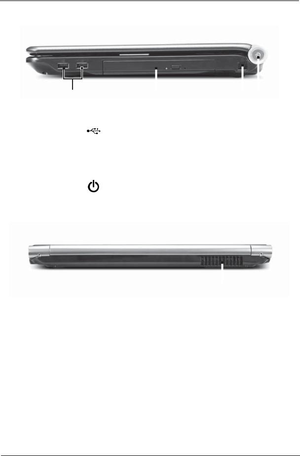
Right View
|
|
|
|
|
|
|
|
|
|
|
|
|
|
|
|
|
|
|
|
|
|
|
|
|
|
|
|
|
|
|
|
|
|
|
|
|
|
|
|
|
|
|
|
|
|
|
|
|
|
|
|
|
|
|
|
|
|
|
|
|
|
|
|
|
|
|
|
|
|
|
|
|
|
|
|
|
|
|
|
|
|
|
|
|
|
|
|
|
|
|
|
|
|
|
|
|
|
|
|
|
|
|
|
|
|
|
|
|
|
|
USB port |
DVD drive |
Modem |
Power |
|||||||||||||||||
|
|
|
|
|
|
|
|
|
|
|
|
|
|
jack |
button |
||||||
|
|
|
|
|
|
|
|
|
|
|
|
|
|
|
|
|
|
|
|
|
|
Component |
|
|
Icon |
|
|
|
Description |
|
|
|
|
|
|
|
|
||||||
|
|
|
|
|
|
|
|
|
|
|
|
|
|
|
|
|
|
|
|
||
USB port |
|
|
|
|
|
|
|
|
|
Plug a USB device (such as a diskette drive, flash drive, |
|||||||||||
|
|
|
|
|
|
|
|
|
|
printer, scanner, camera, keyboard, or mouse) into this |
|||||||||||
|
|
|
|
|
|
|
|
|
|
port. |
|
|
|
|
|
|
|
|
|||
|
|
|
|
|
|
|
|
|
|
|
|
|
|
|
|
|
|
|
|
|
|
DVD drive |
|
|
|
|
|
|
|
|
|
Insert CDs or DVDs into this drive. |
|
|
|
|
|
|
|
|
|||
|
|
|
|
|
|
|
|
|
|
|
|
|
|
|
|
|
|
|
|
||
Modem jack |
|
|
|
|
|
|
|
|
|
Plug a dial-up modem cable into this optional jack. |
|||||||||||
|
|
|
|
|
|
|
|
|
|
|
|
|
|
|
|
|
|
|
|
|
|
|
|
|
|
|
|
|
|
|
|
|
|
|
|
|
|
|
|
|
|
|
|
Power button |
|
|
|
|
|
|
|
|
|
Press to turn the power on or off. You can also configure |
|||||||||||
|
|
|
|
|
|
|
|
|
|
the power button for Sleep/Resume mode. |
|
|
|
|
|||||||
|
|
|
|
|
|
|
|
|
|
|
|
|
|
|
|
|
|
|
|
|
|
Rear View
|
|
|
|
|
|
|
|
|
|
|
|
|
|
Ventilation fan |
|||
|
|
|
|
|
|
Component |
Icon |
Description |
|||
|
|
|
|
|
|
Ventilation fan |
|
Helps cool internal components. |
|||
|
|
Warning: Do not work with the notebook resting on your |
|||
|
|
lap. If the air vents are blocked, the notebook may become |
|||
|
|
hot enough to harm your skin. |
|||
|
|
Caution: Do not block or insert objects into these slots. If |
|||
|
|
these slots are blocked, your notebook may overheat |
|||
|
|
resulting in unexpected shutdown or permanent damage to |
|||
|
|
the notebook. |
|||
|
|
Caution: Provide adequate space around your notebook |
|||
|
|
so air vents are not obstructed. Do not use the notebook on |
|||
|
|
a bed, sofa, rug, or other similar surface. |
|||
Chapter 1 |
7 |
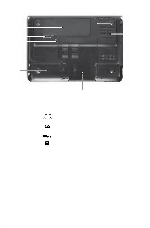
Bottom View
Battery |
|
|
|
|
|
|
|
|
|
|
|
|
|
|
Ventilation |
|
|
|
|
|
|||||||||||
|
|
|
|
|
|
|
|
|
|
|
|
|
|
||
|
|
|
|
|
|
|
|
|
|
|
|
|
|
|
|
Battery |
|
|
|
||||||||||||
|
|
|
slots and |
||||||||||||
|
|
||||||||||||||
|
|
|
|||||||||||||
lock |
|
|
|
|
|
|
|
|
|
|
|
cooling fan |
|||
|
|
|
|
|
|||||||||||
|
|
|
|
|
|
|
|
|
|
|
|||||
|
|
|
|
|
|||||||||||
Battery |
|
|
|
|
|
|
|
|
|||||||
|
|
|
|
|
|
||||||||||
latch |
|
|
|
|
|
|
|
||||||||
|
|
|
|
|
|
||||||||||
Hard drive bay
|
|
|
|
|
|
Memory/ |
|
|
|
|
|
|
Hard drive bay |
|
|
|
|
|
|
|
Component |
|
Icon |
Description |
|||
|
|
|
|
|
|
|
Battery |
|
|
|
|
|
Provides power when the notebook is not plugged into AC |
|
|
|
|
|
|
power. |
|
|
|
|
|
|
|
Battery lock |
|
|
|
|
|
Slide to unlock the battery. |
|
|
|
|
|
|
|
Battery latch |
|
|
|
|
|
Slide to release the battery. |
|
|
|
|
|
|
|
Memory bay |
|
|
|
|
|
Memory modules are located in this bay. |
|
|
|
|
|
||
|
|
|
|
|
|
|
|
|
|
|
|
|
|
Hard drive bay |
|
|
|
|
|
The hard drive is located in this bay. |
|
|
|
|
|
|
|
Ventilation slots |
|
|
|
|
|
Helps cool internal components. |
and cooling fan |
|
|
|
|
|
Warning: Do not work with the notebook resting on your |
|
|
|
|
|
|
lap. If the air vents are blocked, the notebook may become |
|
|
|
|
|
|
hot enough to harm your skin. |
|
|
|
|
|
|
Caution: Do not block or insert objects into these slots. If |
|
|
|
|
|
|
these slots are blocked, your notebook may overheat |
|
|
|
|
|
|
resulting in unexpected shutdown or permanent damage to |
|
|
|
|
|
|
the notebook. |
|
|
|
|
|
|
Caution: Provide adequate space around your notebook |
|
|
|
|
|
|
so air vents are not obstructed. Do not use the notebook on |
|
|
|
|
|
|
a bed, sofa, rug, or other similar surface. |
8 |
Chapter 1 |
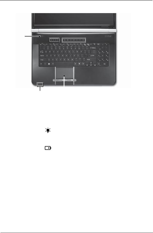
Keyboard Area (selected models)
Speakers
Capacitive Status 
 touch keys
indicators
Keyboard 
|
|
|
|
|
|
|
|
|
|
|
|
|
|
|
|
|
|
|
|
|
|
|
|
|
Power/Battery |
Touchpad |
|||||
|
indicators |
|
|
|
|||
|
|
|
|
|
|
|
|
Component |
|
|
Icon |
|
|
Description |
|
|
|
|
|
|
|
|
|
Speakers |
|
|
|
|
|
|
Left and right speakers deliver stereo audio output. |
|
|
|
|
|
|
|
|
Status indicators |
|
|
|
|
|
|
Inform you when a drive is in use or when a button has |
|
|
|
|
|
|
|
been pressed that affects how the keyboard is used. |
Keyboard |
|
|
|
|
|
|
Provides all the features of a full-sized, computer keyboard. |
|
|
|
|
|
|
|
|
Power indicator |
|
|
|
|
|
|
• LED on - Notebook is on. |
|
|
|
|
|
|
|
• LED blinking - Notebook is in Sleep or Hybrid Sleep |
|
|
|
|
|
|
|
mode. |
|
|
|
|
|
|
|
• LED off - Notebook is off. |
|
|
|
|
|
|
|
|
Battery charge |
|
|
|
|
|
|
• LED orange - Battery is fully charged. |
indicator |
|
|
|
|
|
|
• LED blinking orange - Battery is charging. |
|
|
|
|
|
|
||
|
|
|
|
|
|
||
|
|
|
|
|
|
|
|
|
|
|
|
|
|
|
• LED blinking red - Battery charge is very low. |
|
|
|
|
|
|
|
• LED solid red - Battery is malfunctioning. |
|
|
|
|
|
|
|
Important: This LED only lights up when your notebook is |
|
|
|
|
|
|
|
connected to AC power or the battery charge is very low. |
|
|
|
|
|
|
|
|
Touchpad |
|
|
|
|
|
|
Provides all the functionality of a mouse. |
|
|
|
|
|
|
|
|
Capacitive touch |
|
|
|
|
|
|
Press to access capacitive touch key function. |
keys |
|
|
|
|
|
|
|
Chapter 1 |
9 |
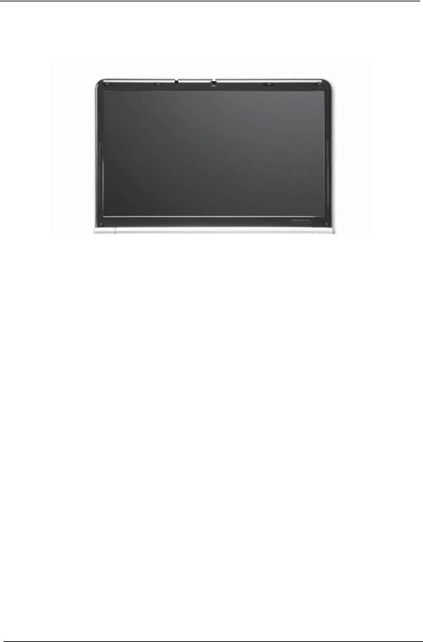
LCD Panel
Microphone Webcam
|
|
|
|
|
|
|
|
|
|
|
|
|
|
|
|
|
|
|
|
|
|
|
|
|
|
|
Component |
Icon |
|
|
|
Description |
|||
|
|
|
|
|
|
|
|
|
Webcam |
|
|
|
|
Use to let others see who they are communicating with |
|||
|
|
|
|
|
when making VoIP calls. |
|||
|
|
|
|
|
|
|
|
|
Microphone |
|
|
|
|
Use to talk through when making Voice over Internet |
|||
|
|
|
|
|
Protocol (VoIP) calls. |
|||
|
|
|
|
|
|
|
|
|
10 |
Chapter 1 |
Status Indicators
Status indicators inform you when a drive is being used or when a button has been pressed that affects how the keyboard is used. The status indicators are located below the screen.
|
|
|
|
|
|
|
|
|
|
|
|
|
|
|
|
|
|
|
|
|
|
|
|
|
|
|
|
|
|
|
|
|
|
|
|
|
|
|
|
|
|
|
|
|
|
|
|
|
|
|
Bluetooth |
|
|
|
|
|
|
|
Num |
|
lock |
|
|
|
|
|
|
|
|
|
|
|
|
|
Battery |
|
|
|||||||
|
|
|
|
HDD |
|
|
Caps lock |
Power |
||||||||
|
|
|
|
|
|
|
|
|
|
|
|
|
|
|
|
|
Indicator |
|
|
Icon |
|
|
|
|
|
Description |
|
|
|||||
|
|
|
|
|
|
|
|
|
|
|
|
|
|
|
||
Bluetooth |
|
|
|
|
|
|
|
• LED on - Bluetooth communication is turned on |
||||||||
|
|
|
|
|
|
|
|
• LED off - Bluetooth communication is turned off |
||||||||
|
|
|
|
|
|
|
|
|
|
|
|
|
|
|
||
Hard drive or disk |
|
|
|
|
|
|
|
• LED blinking - The drive is being accessed |
||||||||
drive |
|
|
|
|
|
|
|
• LED off - The drive is not being accessed |
||||||||
|
|
|
|
|
|
|
|
|||||||||
|
|
|
|
|
|
|
|
|
|
|
|
|
|
|
|
|
Num lock |
|
|
|
|
|
|
|
• LED on - Num lock is turned on |
|
|
||||||
|
|
|
|
|
|
|
|
• LED off - Num lock is turned off |
|
|
||||||
|
|
|
|
|
|
|
|
|
|
|||||||
|
|
|
|
|
|
|
|
|
|
|
|
|
|
|
|
|
Caps lock |
|
|
|
|
|
|
|
• LED on - Caps lock is turned on |
|
|
||||||
|
|
|
|
|
|
|
|
• LED off - Caps lock is turned off |
|
|
||||||
|
|
|
|
|
|
|
|
|
|
|
|
|
|
|
|
|
Battery charge |
|
|
|
|
|
|
|
• LED blue - Battery is fully charged |
|
|
||||||
indicator |
|
|
|
|
|
|
|
• LED red - Battery is charging |
|
|
||||||
|
|
|
|
|
|
|
|
|
|
|||||||
|
|
|
|
|
|
|
|
Important: This LED only lights up when your notebook is |
||||||||
|
|
|
|
|
|
|
|
connected to AC power. |
|
|
|
|
|
|||
|
|
|
|
|
|
|
|
|
|
|
|
|
|
|
|
|
Power indicator |
|
|
|
|
|
|
|
• LED on - Notebook is on. |
|
|
||||||
|
|
|
|
|
|
|
|
• LED blinking - Notebook is in Sleep or Hybrid Sleep mode. |
||||||||
|
|
|
|
|
|
|
|
• LED off - Notebook is off. |
|
|
||||||
|
|
|
|
|
|
|
|
|
|
|
|
|
|
|
|
|
Chapter 1 |
11 |

TouchPad Basics
The following items show you how to use the TouchPad:
1
2 
 3
3
•Move your finger across the TouchPad (1) to move the cursor.
•Press the left (2) and right (3) buttons located beneath the TouchPad to perform selection and execution functions. These two buttons are similar to the left and right buttons on a mouse. Tapping on the TouchPad is the same as clicking the left button.
Function |
Left Button (2) |
Right Button (3) |
Main TouchPad (1) |
|
|
|
|
Execute |
Quickly click twice. |
|
Tap twice (at the same speed |
|
|
|
as double-clicking a mouse |
|
|
|
button). |
|
|
|
|
Select |
Click once. |
|
Tap once. |
|
|
|
|
Drag |
Click and hold, then use |
|
Tap twice (at the same speed |
|
finger on the TouchPad to |
|
as double-clicking a mouse |
|
drag the cursor. |
|
button); rest your finger on |
|
|
|
the TouchPad on the second |
|
|
|
tap and drag the cursor. |
|
|
|
|
Access |
|
Click once. |
|
context menu |
|
|
|
|
|
|
|
NOTE: When using the TouchPad, keep it - and your fingers - dry and clean. The TouchPad is sensitive to finger movement; hence, the lighter the touch, the better the response. Tapping too hard will not increase the TouchPad’s responsiveness.
12 |
Chapter 1 |
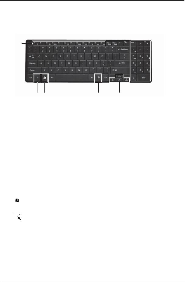
Using the Keyboard
Your notebook features a full-size keyboard that functions the same as a desktop computer keyboard. Many of the keys have been assigned alternate functions, including shortcut keys for Windows, function keys for specific system operations, and the Num Lock keys for the numeric keypad.
Function
keys/ System
keys
Numeric  keypad/
Navigation keys
FN key Windows key |
Application key |
Arrow keys |
Key Types
The keyboard has several different types of keys. Some keys perform specific actions when pressed alone and other actions when pressed in combination with another key.
|
Icon |
Key Type |
Description |
||
|
|
|
|
|
|
|
|
|
|
Function keys |
Press these keys labeled F1 to F12 to perform actions in |
|
|
|
|
|
programs. For example, pressing F1 may open help. Each |
|
|
|
|
|
program uses different function keys for different purposes. |
|
|
|
|
|
See the program documentation to find out more about the |
|
|
|
|
|
function key actions. |
|
|
|
|
|
|
|
|
|
|
System keys |
Press these colored keys in combination with the Fn key to |
|
|
|
|
|
perform specific actions. See “System Keys” on page 15. |
|
|
|
|
|
|
|
|
|
|
Navigation keys |
Press these keys to move the cursor to the beginning of a line, |
|
|
|
|
|
to the end of a line, up the page, down the page, to the |
|
|
|
|
|
beginning of a document, or to the end of a document. |
|
|
|
|
|
|
|
|
|
|
Fn key |
Press the Fn key in combination with a colored system key to |
|
|
|
|
|
perform a specific action. |
|
|
|
|
|
|
|
|
|
|
Windows key |
Press this key to open the Windows Start menu. This key |
|
|
|
|
|
can also be used in combination with other keys to open |
|
|
|
|
|
utilities. See “Windows Keys” on page 14. |
|
|
|
|
|
|
|
|
|
|
Application key |
Press this key for quick access to shortcut menus and help |
|
|
|
|
||
|
|
|
|
||
|
|
|
|
|
assistants in Windows. |
|
|
|
|
|
|
|
|
|
|
|
|
|
|
|
|
|
|
|
|
|
|
|
|
|
|
|
|
|
|
|
|
|
|
Arrow keys |
Press these keys to move the cursor up, down, right, or left. |
|
|
|
|
|
|
Chapter 1 |
13 |

Windows Keys
The keyboard has two keys that perform Windows-specific functions.
Key |
Description |
|
|
Windows key |
Pressed alone, this key has the same effect as clicking on the Windows Start button; |
|
it launches the Start menu. It can also be used with other keys to provide a variety of |
|
functions: |
|
< >: Open or close the Start menu |
|
< > + <D>: Display the desktop |
|
< > + <E>: Open Windows Explore |
|
< > + <F>: Search for a file or folder |
|
< > + <G>: Cycle through Sidebar gadgets |
|
< > + <L>: Lock your computer (if you are connected to a network domain), or |
|
switch users (if you're not connected to a network domain) |
|
< > + <M>: Minimizes all windows |
|
< > + <R>: Open the Run dialog box |
|
< > + <T>: Cycle through programs on the taskbar |
|
< > + <U>: Open Ease of Access Center |
|
< > + <X>: Open Windows Mobility Center |
|
< > + <BREAK>: Display the System Properties dialog box |
|
< > + <SHIFT+M>: Restore minimized windows to the desktop |
|
< > + <TAB>: Cycle through programs on the taskbar by using Windows Flip 3-D |
|
< > + <SPACEBAR>: Bring all gadgets to the front and select Windows Sidebar |
|
<CTRL> + < > + <F>: Search for computers (if you are on a network) |
|
<CTRL> + < > + <TAB>: Use the arrow keys to cycle through programs on the |
|
taskbar by using Windows Flip 3-D |
|
Note: Depending on your edition of Windows Vista, some shortcuts may not function |
|
as described. |
|
|
14 |
Chapter 1 |
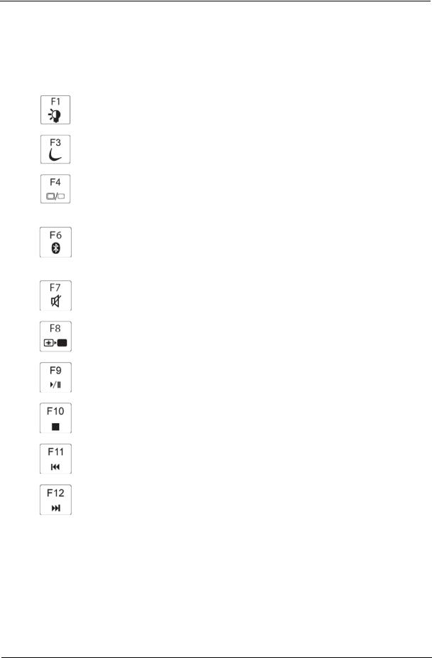
System Keys
The computer employs hotkeys or key combinations to access most of the computer’s controls like screen brightness, Bluetooth and WiFi.
To activate hot keys, press and hold the <Fn> key before pressing the other key in the hotkey combination.
Function Key |
Description |
|
|
|
Turn the capacitive touch key LEDs on or off. |
|
|
|
Enter Sleep mode or Hybrid Sleep mode. Press the power button to leave Sleep |
|
mode. |
|
|
|
Toggle the notebook display in the following order: The LCD. An external monitor |
|
or projector (a monitor or projector must be plugged into the monitor port or |
|
HDMI port on your notebook). Both displays at the same time. |
|
|
|
Turn the optional Bluetooth radio on or off. Warning: Radio frequency wireless |
|
communication can interfere with equipment on commercial aircraft. Current |
|
aviation regulations require wireless devices to be turned off while traveling in an |
|
airplane. Bluetooth communication devices are examples of devices that provide |
|
wireless communication. Important: The wireless network switch must be in the |
|
ON position for this button to work. |
|
|
|
Mute the sound. Press the key combination again to restore the sound. |
|
|
|
Turns the display screen backlight off to save power. Press any key to return. |
|
|
|
Play/ Pause—Plays or pauses the CD or DVD. |
|
|
|
Stop—Stops playing the CD or DVD. |
|
|
|
Previous—Skips back one CD track or DVD chapter. |
|
|
|
Next—Skips ahead one CD track or DVD chapter. |
|
|
Chapter 1 |
15 |

Using the System Utilities
Acer GridVista (dual-display compatible)
NOTE: This feature is only available on certain models.
To enable the dual monitor feature of the notebook, first ensure that the second monitor is connected, then select Start, Control Panel, Display and click on Settings. Select the secondary monitor (2) icon in the display box and then click the check box Extend my windows desktop onto this monitor. Finally, click Apply to confirm the new settings and click OK to complete the process.
Acer GridVista is a handy utility that offers four pre-defined display settings so you can view multiple windows on the same screen. To access this function, please go to Start´ All Programs and click on Acer GridVista. You may choose any one of the four display settings indicated below:
Double (vertical), Triple (primary at left), Triple (primary at right), or Quad Acer Gridvista is dual-display compatible, allowing two displays to be partitioned independently.
Acer Gridvista is dual-display compatible, allowing two displays to be partitioned independently. AcerGridVista is simple to set up:
1.Run Acer GridVista and select your preferred screen configuration for each display from the task bar.
2.Drag and drop each window into the appropriate grid.
3.Enjoy the convenience of a well-organized desktop.
NOTE: Please ensure that the resolution setting of the second monitor is set to the manufacturer's recommended value.
16 |
Chapter 1 |

Hardware Specifications and Configurations
Processor
|
|
Item |
|
|
|
|
|
|
Specification |
|
|
|
|
|||||
|
|
|
|
|
|
|
|
|
|
|
|
|
|
|
|
|
||
|
CPU |
|
|
|
Intel® Core™ 2 Duo T6400 2.0GHz |
|
|
|
|
|
|
|||||||
|
|
|
|
|
|
|
|
|
|
|
|
|
|
|
|
|
|
|
|
Core Logic |
Intel PM45 |
|
|
|
|
|
|
|
|
|
|
|
|||||
|
|
|
|
|
ICH9-M |
|
|
|
|
|
|
|
|
|
|
|
||
|
|
|
|
|
|
|
|
|
|
|
|
|
|
|
|
|
||
|
Power |
See table below |
|
|
|
|
|
|
|
|
|
|||||||
|
|
|
|
|
|
|
|
|
|
|
|
|
|
|
|
|
|
|
|
On-die Cache |
2 MB |
|
|
|
|
|
|
|
|
|
|
|
|||||
|
|
|
|
|
|
|
|
|
|
|
|
|
|
|
|
|
|
|
|
Front Side Bus |
800 MHz |
|
|
|
|
|
|
|
|
|
|
|
|||||
|
|
|
|
|
|
|
|
|
|
|
|
|
|
|
|
|
|
|
Processor Specifications |
|
|
|
|
|
|
|
|
|
|
|
|||||||
|
|
|
|
|
|
|
|
|
|
|
|
|
|
|
|
|
|
|
Item |
|
|
CPU |
|
Cores |
|
Bus |
Mfg |
|
Cache |
|
Package |
Core |
|
Acer P/N |
|||
|
|
Speed |
|
|
Speed |
Tech |
|
Size |
|
Voltage |
|
|||||||
|
|
|
|
|
|
|
|
|
|
|
|
|
||||||
|
|
|
|
|
|
|
|
|
|
|
|
|
|
|
|
|
||
T1600 |
|
|
1.66 GHz |
|
2 |
|
667 MHz |
65 nm |
|
1 |
|
FCPGA |
1.075V- |
KC.16001.CMT |
||||
|
|
|
|
|
|
|
|
|
|
|
|
|
|
|
1.175V |
|
|
|
|
|
|
|
|
|
|
|
|
|
|
|
|
|
|
|
|
||
T1700 |
|
|
1.83 GHz |
|
2 |
|
667 MHz |
65 nm |
|
1 |
|
FCPGA |
1.075V- |
KC.17001.CMT |
||||
|
|
|
|
|
|
|
|
|
|
|
|
|
|
|
1.175V |
|
|
|
|
|
|
|
|
|
|
|
|
|
|
|
|
|
|
|
|
||
T4200 |
|
|
2.0 GHz |
|
2 |
|
800 MHz |
45 nm |
|
1 |
|
FCPGA |
|
KC.42001.DTP |
||||
|
|
|
|
|
|
|
|
|
|
|
|
|
|
|
|
|
||
T6400 |
|
|
2.0 GHz |
|
2 |
|
800 MHz |
45 nm |
|
3 |
|
FCPGA |
1.000V- |
KC.64001.DTP |
||||
|
|
|
|
|
|
|
|
|
|
|
|
|
|
|
1.250V |
|
|
|
|
|
|
|
|
|
|
|
|
|
|
|
|
|
|
|
|
||
T6600 |
|
|
2.2 GHz |
|
2 |
|
800 MHz |
45 nm |
|
2 |
|
FCPGA |
1.00V- |
KC.66001.DTP |
||||
|
|
|
|
|
|
|
|
|
|
|
|
|
|
|
1.250V |
|
|
|
|
|
|
|
|
|
|
|
|
|
|
|
|
|
|
|
|
||
P7350 |
|
|
2.0 GHz |
|
2 |
|
1066 MHz |
45 nm |
|
3 |
|
FCPGA |
1.062C- |
KC.73501.DPP |
||||
|
|
|
|
|
|
|
|
|
|
|
|
|
|
|
1.150V |
|
|
|
|
|
|
|
|
|
|
|
|
|
|
|
|
|
|
|
|
||
P7450 |
|
|
2.13 GHz |
|
2 |
|
1066 MHz |
45 nm |
|
3 |
|
FCPGA |
1.00V- |
KC.74501.DPP |
||||
|
|
|
|
|
|
|
|
|
|
|
|
|
|
|
1.250V |
|
|
|
|
|
|
|
|
|
|
|
|
|
|
|
|
|
|
|
|
||
P8400 |
|
|
2.26 GHz |
|
2 |
|
1066 MHz |
45 nm |
|
3 |
|
FCPGA |
1.050V- |
KC.84R01.DPP |
||||
|
|
|
|
|
|
|
|
|
|
|
|
|
|
|
1.150V |
|
|
|
|
|
|
|
|
|
|
|
|
|
|
|
|
|
|
|
|
||
P8600 |
|
|
2.4 GHz |
|
2 |
|
1066 MHz |
45 nm |
|
3 |
|
FCPGA |
1.050V- |
KC.86R01.DPP |
||||
|
|
|
|
|
|
|
|
|
|
|
|
|
|
|
1.150V |
|
|
|
|
|
|
|
|
|
|
|
|
|
|
|
|
|
|
|
|
||
P8700 |
|
|
2.53 GHz |
|
2 |
|
1066 MHz |
45 nm |
|
3 |
|
FCPGA |
1.00V - |
KC.87R01.DPP |
||||
|
|
|
|
|
|
|
|
|
|
|
|
|
|
|
1.25V |
|
|
|
|
|
|
|
|
|
|
|
|
|
|
|
|
|
|
|
|
||
T9500 |
|
|
2.6 GHz |
|
2 |
|
800 MHz |
45 nm |
|
6 |
|
FCPGA |
1.000V- |
KC.95S01.DTP |
||||
|
|
|
|
|
|
|
|
|
|
|
|
|
|
|
1.250V |
|
|
|
|
|
|
|
|
|
|
|
|
|
|
|
|
|
|
|
|
||
Celeron 585 |
|
|
2.16 GHz |
|
|
|
667 MHz |
65 nm |
|
1 |
|
FCPGA |
0.95- |
KC.N0001.585 |
||||
|
|
|
|
|
|
|
|
|
|
|
|
|
|
|
1.30V |
|
|
|
|
|
|
|
|
|
|
|
|
|
|
|
|
|
|
|
|
||
Celeron 900 |
|
|
2.2 GHz |
|
|
|
800 MHz |
45 nm |
|
1 |
|
FCPGA |
|
KC.N0001.900 |
||||
|
|
|
|
|
|
|
|
|
|
|
|
|
|
|
|
|||
CPU Fan True Value Table |
|
|
|
|
|
|
|
|
|
|
|
|||||||
|
|
|
|
|
|
|
|
|
|
|
|
|
|
|
|
|
|
|
|
|
|
|
Fan On Temp (°C) |
|
Fan Speed (rpm) |
|
SPL Spec (dBA) |
|
|
|
|||||||
|
|
|
|
|
|
|
|
|
|
|
|
|
|
|
|
|
|
|
|
|
|
|
38 |
|
|
|
|
2700 |
|
|
|
31 |
|
|
|
|
|
|
|
|
|
|
|
|
|
|
|
|
|
|
|
|
|
|
||
|
|
|
|
42 |
|
|
|
|
2900 |
|
|
|
34 |
|
|
|
|
|
|
|
|
|
|
|
|
|
|
|
|
|
|
|
|
|
|
||
|
|
|
|
65 |
|
|
|
|
3200 |
|
|
|
37 |
|
|
|
|
|
|
|
|
|
|
|
|
|
|
|
|
|
|
|
|
|
|
||
|
|
|
|
75 |
|
|
|
|
3500 |
|
|
|
40 |
|
|
|
|
|
|
|
|
|
|
|
|
|
|
|
|
|
|
|
|
|
|
|
|
•Throttling 50%: On=100°C, Off=90°C
•OS Shutdown: 105°C
•H/W Shutdown: 96°C
Chapter 1 |
17 |

Northbridge
Item |
|
|
|
Specification |
|
|
|
|
|
|
|
Chipset |
Intel PM45 |
|
|
|
|
Features |
• |
Intel® Active Management Technology (Intel® AMT) 4.0 |
|
||
|
• Dual-channel DDR3 and DDR2 memory support |
|
|||
|
• 1066 MHz system bus |
|
|||
|
• PCI Express* x16 graphics port and PCI Express x1 I/O ports |
|
|||
|
• |
Serial ATA |
|
|
|
|
• Hi-Speed USB 2.0 connectivity |
|
|||
|
• Supports dual graphics with ATI CrossfireX |
|
|||
|
|
|
|
|
|
Southbridge |
|
|
|
|
|
|
|
|
|
|
|
Item |
|
|
|
Specification |
|
|
|
|
|
|
|
Chipset |
|
ICH9-M |
|
|
|
|
|
|
|
|
|
Package |
|
676 µ-BGA |
|
|
|
|
|
|
|
|
|
Features |
|
• Direct connection to the GMCH via Direct Media Interface |
|
||
|
|
• Six PCI Express root ports |
|
||
|
|
• Four-port Serial ATA controller |
|
||
|
|
• Up to twelve USB 2.0 ports |
|
||
|
|
• Intel® High Definition Audio interface. |
|
||
|
|
|
|
|
|
BIOS |
|
|
|
|
|
|
|
|
|
|
|
|
Item |
|
|
Specification |
|
|
|
|
|
|
|
BIOS vendor |
|
|
Insyde H20 |
|
|
BIOS Version |
|
|
V0.07 |
|
|
|
|
|
|
||
BIOS ROM type |
|
Flash |
|
||
|
|
|
|
|
|
Features |
|
|
• |
Flash ROM 1MB |
|
|
|
|
• |
Support ISIPP |
|
|
|
|
• |
Support Acer UI |
|
|
|
|
• Support multi-boot |
|
|
|
|
|
• Suspend to RAM (S3)/Disk (S4) |
|
|
|
|
|
• Various hot-keys for system control |
|
|
|
|
|
• Support SMBUS 2.0, PCI2.3 |
|
|
|
|
|
• ACPI 2.0 compliance with Intel Speed Step Support C1, C2, |
|
|
|
|
|
|
C3, C4,C6 and S3, S4 for mobile CPU |
|
|
|
|
• DMI utility for BIOS serial number configurable/asset tag |
|
|
|
|
|
• |
Support PXE |
|
|
|
|
• |
Support Y2K solution |
|
|
|
|
• Support Win Flash Wake on LAN from S3 |
|
|
|
|
|
• Wake on LAN form S4 in AC mode |
|
|
|
|
|
• |
System information |
|
|
|
|
|
|
|
System Memory |
|
|
|
|
|
|
|
|
|
|
|
|
Item |
|
|
Specification |
|
|
|
|
|
||
Memory controller |
|
Intel PM45 with ICH9M |
|
||
Memory size |
|
|
2 GB (4 GB for 64-bit OS) |
|
|
|
|
|
|
||
DIMM socket number |
2 |
|
|
||
|
|
|
|||
Supports memory size per socket |
2 GB (4 GB for 64-bit OS) |
|
|||
|
|
|
|
|
|
18 |
Chapter 1 |

Item |
|
Specification |
|
|
|
|
|
Supports maximum memory size |
4 GB (8 GB for 64-bit OS) |
|
|
Supports DIMM type |
DDRIII |
|
|
|
|
|
|
Supports DIMM Speed |
800 MHz |
|
|
|
|
|
|
Supports DIMM voltage |
1.5V |
|
|
|
|
|
|
Cache |
1, 2, or 6 MB L2 |
|
|
|
|
|
|
Memory Combinations |
|
|
|
|
|
|
|
Slot 1 |
Slot 2 |
|
Total Memory |
|
|
|
|
0MB |
512MB |
|
512MB |
0MB |
1024MB |
|
1024MB |
|
|
|
|
0MB |
2048MB |
|
2048MB |
|
|
|
|
512MB |
512MB |
|
1024MB |
|
|
|
|
512MB |
1024MB |
|
1536MB |
|
|
|
|
512MB |
2048MB |
|
2560MB |
|
|
|
|
1024MB |
0MB |
|
1024MB |
|
|
|
|
1024MB |
512MB |
|
1536MB |
|
|
|
|
1024MB |
1024MB |
|
2048MB |
|
|
|
|
1024MB |
2048MB |
|
3072MB |
|
|
|
|
2048MB |
0MB |
|
2048MB |
|
|
|
|
2048MB |
512MB |
|
2560MB |
|
|
|
|
2048MB |
1024MB |
|
3072MB |
|
|
|
|
2048MB |
2048MB |
|
4096MB |
|
|
|
|
NOTE: Above table lists some system memory configurations. You may combine DIMMs with various capacities to form other combinations. On above table, the configuration of slot 1 and slot 2 could be reversed.
Graphics Controller
|
Item |
|
|
|
Specification |
|
|
|
|
|
|
|
|
|
VGA Chip |
|
ATI Mobility Radeon™ HD 4570 |
|
||
|
|
|
|
|
|
|
|
Graphics Memory |
|
2304 MB of HyperMemory™ (512 MB of dedicated DDR2 VRAM, up to 1792 MB of |
|
||
|
|
|
shared system memory) |
|
||
|
|
|
|
|
|
|
|
Supports |
|
• |
Unified Video Decoder (UVD) |
|
|
|
|
|
• OpenEXR High Dynamic-Range (HDR) technology |
|
||
|
|
|
• |
Shader Model 4.1 |
|
|
|
|
|
• |
Microsoft® DirectX® 10.1Mobile |
|
|
|
|
|
• Dual independent display support |
|
||
|
|
|
|
|
|
|
|
LAN Interface |
|
|
|
|
|
|
|
|
|
|
|
|
|
Item |
|
|
Specification |
|
|
|
|
|
|
|
|
|
|
LAN Chipset |
|
|
Broadcom BCM5784 for 10/100/1000LAN |
|
|
|
|
|
|
|
|
|
|
LAN connector type |
|
|
RJ45 |
|
|
|
|
|
|
|
||
|
LAN connector location |
|
Left side |
|
||
|
|
|
|
|
|
|
|
Features |
|
|
Support for 10/100/1000 |
|
|
|
|
|
|
|
|
|
Chapter 1 |
19 |

Wireless Module 802.11b/g
|
|
Item |
|
|
|
|
|
Specification |
|
||||
|
|
|
|
|
|
|
|
|
|
|
|
|
|
|
Manufacturer |
|
|
|
|
|
|
|
|
|
|
||
|
Model |
|
|
|
|
|
|
|
|
|
|
||
|
|
|
|
|
|
|
|
|
|
|
|
|
|
|
Modem Device |
|
• |
|
|
|
|
|
|
|
|||
|
|
|
|
|
|
|
|
|
|
|
|
|
|
|
Interface |
|
|
|
|
|
|
|
|
|
|
||
|
|
|
|
|
|
|
|
|
|
|
|
|
|
|
Bluetooth |
|
|
|
|
|
|
|
|
|
|
||
|
|
|
|
|
|
|
|
|
|
|
|
|
|
|
|
Item |
|
|
|
|
|
Specification |
|
||||
|
|
|
|
|
|
|
|
|
|
|
|
|
|
|
Model |
|
|
|
|
|
|
|
|
|
|
||
|
|
|
|
|
|
|
|
|
|
|
|
|
|
|
Operating Frequency |
|
|
|
|
|
|
|
|
|
|
||
|
|
|
|
|
|
|
|
|
|
|
|
|
|
|
Channel Numbers |
|
|
|
|
|
|
|
|
|
|
||
|
|
|
|
|
|
|
|
|
|
|
|
|
|
|
Transmitter Output Power |
|
|
|
|
|
|
|
|
|
|
||
|
|
|
|
|
|
|
|
|
|
|
|
|
|
|
Coverage |
|
|
|
|
|
|
|
|
|
|
||
|
|
|
|
|
|
|
|
|
|
|
|
|
|
|
Receiver Sensitivity |
|
|
|
|
|
|
|
|
|
|
||
|
|
|
|
|
|
|
|
|
|
|
|
|
|
|
Maximum Receiver Signal |
|
|
|
|
|
|
|
|
|
|
||
|
|
|
|
|
|
|
|
|
|
|
|
|
|
|
Operating Voltage |
|
|
|
|
|
|
|
|
|
|
||
|
|
|
|
|
|
|
|
|
|
|
|
|
|
|
Interface |
|
|
|
|
|
|
|
|
|
|
||
|
|
|
|
|
|
|
|
|
|
|
|
|
|
|
Hard Disk Drive Interface |
|
|
|
|
|
|
|
|
|
|
||
|
|
|
|
|
|
|
|
|
|
|
|
|
|
|
|
Item |
|
|
|
|
Specification |
|
|
|
|||
|
|
|
|
|
|
|
|
|
|
|
|
|
|
|
|
Vendor |
|
|
|
|
Seagate |
|
|
|
|||
|
|
|
|
|
|
|
|
|
|
|
|||
|
|
Model Name |
ST9160310AS |
|
ST9320320AS |
|
ST9500325AS |
|
|
||||
|
|
|
|
|
|
|
|
|
|
|
|
|
|
|
|
Capacity (MB) |
160 |
|
|
320 |
|
|
500 |
|
|
||
|
|
|
|
|
|
|
|
|
|
|
|
|
|
|
|
Bytes per sector |
|
|
|
|
512 |
|
|
|
|
||
|
|
|
|
|
|
|
|
|
|
|
|
|
|
|
|
Data heads |
2 |
|
|
4 |
|
|
|
4 |
|
|
|
|
|
|
|
|
|
|
|
|
|
|
|
|
|
|
|
Drive Format |
|
|
|
|
|
|
|
|
|
|
|
|
|
|
|
|
|
|
|
|
|
|
|
|
|
|
|
Disks |
1 |
|
|
2 |
|
|
|
2 |
|
|
|
|
|
|
|
|
|
|
|
|
|
|
|
|
|
|
|
Spindle speed (RPM) |
|
|
|
|
5,400 |
|
|
|
|
||
|
|
|
|
|
|
|
|
|
|
|
|
|
|
|
|
Performance Specifications |
|
|
|
|
|
|
|
|
|
|
|
|
|
|
|
|
|
|
|
|
|
|
|
|
|
|
|
Buffer size |
|
|
|
|
8 MB |
|
|
|
|||
|
|
|
|
|
|
|
|
|
|
|
|
|
|
|
|
Interface |
|
|
|
|
SATA |
|
|
|
|||
|
|
|
|
|
|
|
|
|
|
|
|
||
|
|
Internal transfer rate |
830 |
|
|
|
|
1175 |
|
|
|||
|
|
(Mbits/sec max) |
|
|
|
|
|
|
|
|
|
|
|
|
|
|
|
|
|
|
|
|
|
|
|
|
|
|
|
I/O data transfer rate |
|
|
|
|
300 |
|
|
|
|
||
|
|
(Mbytes/sec max) |
|
|
|
|
|
|
|
|
|
|
|
|
|
|
|
|
|
|
|
|
|
|
|
|
|
|
|
DC Power Requirements |
|
|
|
|
|
|
|
|
|
|
|
|
|
|
|
|
|
|
|
|
|
|
|
|
|
|
|
Voltage tolerance |
|
|
|
|
5V(DC) +/- 5% |
|
|
|
|||
|
|
|
|
|
|
|
|
|
|
|
|
|
|
|
|
|
|
|
|
|
|
|
|
|
|
|
|
|
|
Item |
|
|
|
|
|
Specifications |
|
|
|
||
|
|
|
|
|
|
|
|
|
|||||
|
|
Vendor & Model Name |
|
Toshiba MK5055/2555GSX |
|
Toshiba MK3255/1655GSX |
|
|
|||||
|
|
|
|
|
|
|
|
|
|
|
|||
|
|
Capacity |
|
500/250GB |
|
|
320/160GB |
|
|
|
|||
|
|
|
|
|
|
|
|
|
|
|
|
|
|
|
|
Bytes per sector |
|
|
|
|
|
512 |
|
|
|
|
|
|
|
|
|
|
|
|
|
|
|
|
|
|
|
|
|
Data heads |
|
4/2 |
|
|
|
|
4/2 |
|
|
|
|
|
|
|
|
|
|
|
|
|
|
|
|
|
|
|
|
Drive Format |
|
|
|
|
|
|
|
|
|
|
|
|
|
|
|
|
|
|
|
|
|
|
|
|
|
|
|
Disks |
|
2/1 |
|
|
|
|
2/1 |
|
|
|
|
|
|
|
|
|
|
|
|
|
|
|
|
|
|
|
|
|
|
|
|
|
|
|
|
|
|
|
|
20 |
Chapter 1 |
Loading...