


 Loading...
Packard Bell EasyNote Butterfly Touch Series
Service Guide
Service guide files and updates are available on the ACER/CSD web; for more information, please refer to http://csd.acer.com.tw
PRINTED IN TAIWAN

Revision History
Please refer to the table below for the updates made on this service guide.
Date |
Chapter |
Updates |
|
|
|
|
|
|
|
|
|
|
|
|
ii

Copyright
Copyright © 2009 by Acer Incorporated. All rights reserved. No part of this publication may be reproduced, transmitted, transcribed, stored in a retrieval system, or translated into any language or computer language, in any form or by any means, electronic, mechanical, magnetic, optical, chemical, manual or otherwise, without the prior written permission of Acer Incorporated.
Disclaimer
The information in this guide is subject to change without notice.
Acer Incorporated makes no representations or warranties, either expressed or implied, with respect to the contents hereof and specifically disclaims any warranties of merchantability or fitness for any particular purpose. Any Acer Incorporated software described in this manual is sold or licensed "as is". Should the programs prove defective following their purchase, the buyer (and not Acer Incorporated, its distributor, or its dealer) assumes the entire cost of all necessary servicing, repair, and any incidental or consequential damages resulting from any defect in the software.
Acer is a registered trademark of Acer Corporation. Intel is a registered trademark of Intel Corporation.
Pentium and Pentium II/III are trademarks of Intel Corporation.
Other brand and product names are trademarks and/or registered trademarks of their respective holders.
iii

Conventions
The following conventions are used in this manual:
SCREEN MESSAGES |
Denotes actual messages that |
|
appear on screen. |
|
|
NOTE |
Gives bits and pieces of additional |
|
information related to the current |
|
topic. |
|
|
WARNING |
Alerts you to any damage that might |
|
result from doing or not doing |
|
specific actions. |
|
|
CAUTION |
Gives precautionary measures to |
|
avoid possible hardware or software |
|
problems. |
|
|
IMPORTANT |
Reminds you to do specific actions |
|
relevant to the accomplishment of |
|
procedures. |
|
|
iv

Preface
Before using this information and the product it supports, please read the following general information.
1.This Service Guide provides you with all technical information relating to the BASIC CONFIGURATION decided for Acer's "global" product offering. To better fit local market requirements and enhance product competitiveness, your regional office MAY have decided to extend the functionality of a machine (e.g. add-on card, modem, or extra memory capability). These LOCALIZED FEATURES will NOT be covered in this generic service guide. In such cases, please contact your regional offices or the responsible personnel/channel to provide you with further technical details.
2.Please note WHEN ORDERING FRU PARTS, that you should check the most up-to-date information available on your regional web or channel. If, for whatever reason, a part number change is made, it will not be noted in the printed Service Guide. For ACER-AUTHORIZED SERVICE PROVIDERS, your Acer office may have a DIFFERENT part number code to those given in the FRU list of this printed Service Guide. You MUST use the list provided by your regional Acer office to order FRU parts for repair and service of customer machines.
v

vi

Table of Contents
System Specifications |
1 |
Features . . . . . . . . . . . . . . . . . . . . . . . . . . . . . . . . . . . . . . . . . . . . . . . . . . . . . . . . . . . .1
System Block Diagram . . . . . . . . . . . . . . . . . . . . . . . . . . . . . . . . . . . . . . . . . . . . . . . . .3
Your Notebook Tour . . . . . . . . . . . . . . . . . . . . . . . . . . . . . . . . . . . . . . . . . . . . . . . . . . .4
Front View . . . . . . . . . . . . . . . . . . . . . . . . . . . . . . . . . . . . . . . . . . . . . . . . . . . . . . .4
Closed Front View . . . . . . . . . . . . . . . . . . . . . . . . . . . . . . . . . . . . . . . . . . . . . . . . .5
Left View . . . . . . . . . . . . . . . . . . . . . . . . . . . . . . . . . . . . . . . . . . . . . . . . . . . . . . . .6
Right View . . . . . . . . . . . . . . . . . . . . . . . . . . . . . . . . . . . . . . . . . . . . . . . . . . . . . . .6
Base View . . . . . . . . . . . . . . . . . . . . . . . . . . . . . . . . . . . . . . . . . . . . . . . . . . . . . . .7
Rear View . . . . . . . . . . . . . . . . . . . . . . . . . . . . . . . . . . . . . . . . . . . . . . . . . . . . . . .8
Indicators . . . . . . . . . . . . . . . . . . . . . . . . . . . . . . . . . . . . . . . . . . . . . . . . . . . . . . .8
TouchPad Basics . . . . . . . . . . . . . . . . . . . . . . . . . . . . . . . . . . . . . . . . . . . . . . . . .9
Using the Keyboard . . . . . . . . . . . . . . . . . . . . . . . . . . . . . . . . . . . . . . . . . . . . . . . . . .10
Lock Keys and embedded numeric keypad . . . . . . . . . . . . . . . . . . . . . . . . . . . .10
Windows Keys . . . . . . . . . . . . . . . . . . . . . . . . . . . . . . . . . . . . . . . . . . . . . . . . . .11
Hot Keys . . . . . . . . . . . . . . . . . . . . . . . . . . . . . . . . . . . . . . . . . . . . . . . . . . . . . . .12
Special Keys . . . . . . . . . . . . . . . . . . . . . . . . . . . . . . . . . . . . . . . . . . . . . . . . . . . .13
Hardware Specifications and Configurations . . . . . . . . . . . . . . . . . . . . . . . . . . . . . . .14
System Utilities |
23 |
BIOS Setup Utility . . . . . . . . . . . . . . . . . . . . . . . . . . . . . . . . . . . . . . . . . . . . . . . . . . . .23
Navigating the BIOS Utility . . . . . . . . . . . . . . . . . . . . . . . . . . . . . . . . . . . . . . . . .23
Information . . . . . . . . . . . . . . . . . . . . . . . . . . . . . . . . . . . . . . . . . . . . . . . . . . . . .24
Main . . . . . . . . . . . . . . . . . . . . . . . . . . . . . . . . . . . . . . . . . . . . . . . . . . . . . . . . . .25
Security . . . . . . . . . . . . . . . . . . . . . . . . . . . . . . . . . . . . . . . . . . . . . . . . . . . . . . . .26
Boot . . . . . . . . . . . . . . . . . . . . . . . . . . . . . . . . . . . . . . . . . . . . . . . . . . . . . . . . . . .29
Exit . . . . . . . . . . . . . . . . . . . . . . . . . . . . . . . . . . . . . . . . . . . . . . . . . . . . . . . . . . .30
BIOS Flash Utility . . . . . . . . . . . . . . . . . . . . . . . . . . . . . . . . . . . . . . . . . . . . . . . . . . . .31
DOS Flash Utility . . . . . . . . . . . . . . . . . . . . . . . . . . . . . . . . . . . . . . . . . . . . . . . . .32
WinFlash Utility . . . . . . . . . . . . . . . . . . . . . . . . . . . . . . . . . . . . . . . . . . . . . . . . . .33
Remove HDD/BIOS Password Utilities . . . . . . . . . . . . . . . . . . . . . . . . . . . . . . . . . . . .34
Removing BIOS Passwords: . . . . . . . . . . . . . . . . . . . . . . . . . . . . . . . . . . . . . . . .35
Miscellaneous Utilities . . . . . . . . . . . . . . . . . . . . . . . . . . . . . . . . . . . . . . . . . . . . .36
Machine Disassembly and Replacement |
39 |
Disassembly Requirements . . . . . . . . . . . . . . . . . . . . . . . . . . . . . . . . . . . . . . . . . . . |
.39 |
General Information . . . . . . . . . . . . . . . . . . . . . . . . . . . . . . . . . . . . . . . . . . . . . . . . . |
.39 |
Pre-disassembly Instructions . . . . . . . . . . . . . . . . . . . . . . . . . . . . . . . . . . . . . . |
.39 |
Disassembly Process . . . . . . . . . . . . . . . . . . . . . . . . . . . . . . . . . . . . . . . . . . . . . |
40 |
External Module Disassembly Process . . . . . . . . . . . . . . . . . . . . . . . . . . . . . . . . . . . |
41 |
External Modules Disassembly Flowchart . . . . . . . . . . . . . . . . . . . . . . . . . . . . . |
41 |
Removing the Dummy Card . . . . . . . . . . . . . . . . . . . . . . . . . . . . . . . . . . . . . . . . |
42 |
Removing the Battery Pack . . . . . . . . . . . . . . . . . . . . . . . . . . . . . . . . . . . . . . . . |
42 |
Removing the SIM Card . . . . . . . . . . . . . . . . . . . . . . . . . . . . . . . . . . . . . . . . . . . |
44 |
Removing the Module Cover . . . . . . . . . . . . . . . . . . . . . . . . . . . . . . . . . . . . . . . |
45 |
Removing the Hard Disk Drive Module . . . . . . . . . . . . . . . . . . . . . . . . . . . . . . . . |
46 |
Removing the DIMM Module . . . . . . . . . . . . . . . . . . . . . . . . . . . . . . . . . . . . . . . |
48 |
Removing the WLAN Board . . . . . . . . . . . . . . . . . . . . . . . . . . . . . . . . . . . . . . . . |
49 |
Removing the 3G Module . . . . . . . . . . . . . . . . . . . . . . . . . . . . . . . . . . . . . . . . . . |
50 |
Main Unit Disassembly Process . . . . . . . . . . . . . . . . . . . . . . . . . . . . . . . . . . . . . . . . . |
52 |
Main Unit Disassembly Flowchart . . . . . . . . . . . . . . . . . . . . . . . . . . . . . . . . . . . . |
52 |
Removing the Keyboard . . . . . . . . . . . . . . . . . . . . . . . . . . . . . . . . . . . . . . . . . . . |
54 |
Removing the Hinge Covers . . . . . . . . . . . . . . . . . . . . . . . . . . . . . . . . . . . . . . . . |
56 |
Removing the Upper Cover . . . . . . . . . . . . . . . . . . . . . . . . . . . . . . . . . . . . . . . . |
58 |
vii

Table of Contents
Removing the Bluetooth Module . . . . . . . . . . . . . . . . . . . . . . . . . . . . . . . . . . . . .62
Removing the Button Board . . . . . . . . . . . . . . . . . . . . . . . . . . . . . . . . . . . . . . . .63
Removing the I/O Board . . . . . . . . . . . . . . . . . . . . . . . . . . . . . . . . . . . . . . . . . . .67
Removing the LED Board . . . . . . . . . . . . . . . . . . . . . . . . . . . . . . . . . . . . . . . . . .69
Removing the CRT Board . . . . . . . . . . . . . . . . . . . . . . . . . . . . . . . . . . . . . . . . . .71
Removing the Mainboard . . . . . . . . . . . . . . . . . . . . . . . . . . . . . . . . . . . . . . . . . .74
Removing the Thermal Module . . . . . . . . . . . . . . . . . . . . . . . . . . . . . . . . . . . . . .77
Removing the RTC Battery . . . . . . . . . . . . . . . . . . . . . . . . . . . . . . . . . . . . . . . . .78
Removing the Speaker Modules . . . . . . . . . . . . . . . . . . . . . . . . . . . . . . . . . . . . .78
Removing the LCD Module . . . . . . . . . . . . . . . . . . . . . . . . . . . . . . . . . . . . . . . . .80
LCD Module Disassembly Process . . . . . . . . . . . . . . . . . . . . . . . . . . . . . . . . . . . . . .82
LCD Module Disassembly Flowchart . . . . . . . . . . . . . . . . . . . . . . . . . . . . . . . . .82
Removing the LCD Bezel . . . . . . . . . . . . . . . . . . . . . . . . . . . . . . . . . . . . . . . . . .84
Removing the Camera Board . . . . . . . . . . . . . . . . . . . . . . . . . . . . . . . . . . . . . . .87
Removing the Microphone . . . . . . . . . . . . . . . . . . . . . . . . . . . . . . . . . . . . . . . . .88
Removing the LCD Panel . . . . . . . . . . . . . . . . . . . . . . . . . . . . . . . . . . . . . . . . . .89
Removing the LCD Cable . . . . . . . . . . . . . . . . . . . . . . . . . . . . . . . . . . . . . . . . . .91
Removing the LCD Brackets . . . . . . . . . . . . . . . . . . . . . . . . . . . . . . . . . . . . . . . .93
Removing the Touchscreen Board . . . . . . . . . . . . . . . . . . . . . . . . . . . . . . . . . . .94
Removing the Hinge . . . . . . . . . . . . . . . . . . . . . . . . . . . . . . . . . . . . . . . . . . . . . .95
Removing the Antennas . . . . . . . . . . . . . . . . . . . . . . . . . . . . . . . . . . . . . . . . . . .97
LCD Reassembly Procedure . . . . . . . . . . . . . . . . . . . . . . . . . . . . . . . . . . . . . . . . . .101
Replacing the Antennas . . . . . . . . . . . . . . . . . . . . . . . . . . . . . . . . . . . . . . . . . .101
Replacing the Hinge . . . . . . . . . . . . . . . . . . . . . . . . . . . . . . . . . . . . . . . . . . . . .103
Replacing the Touchscreen Board. . . . . . . . . . . . . . . . . . . . . . . . . . . . . . . . . . .104
Replacing the LCD Brackets . . . . . . . . . . . . . . . . . . . . . . . . . . . . . . . . . . . . . . .105
Replacing the LCD Cable . . . . . . . . . . . . . . . . . . . . . . . . . . . . . . . . . . . . . . . . .106
Replacing the LCD Panel . . . . . . . . . . . . . . . . . . . . . . . . . . . . . . . . . . . . . . . . .108
Replacing the Microphone. . . . . . . . . . . . . . . . . . . . . . . . . . . . . . . . . . . . . . . . .110
Replacing the Camera Board . . . . . . . . . . . . . . . . . . . . . . . . . . . . . . . . . . . . . .111
Replacing the LCD Bezel . . . . . . . . . . . . . . . . . . . . . . . . . . . . . . . . . . . . . . . . .112
Main Unit Reassembly Process . . . . . . . . . . . . . . . . . . . . . . . . . . . . . . . . . . . . . . . .115
Replacing the LCD Module . . . . . . . . . . . . . . . . . . . . . . . . . . . . . . . . . . . . . . . .115
Replacing the RTC Battery . . . . . . . . . . . . . . . . . . . . . . . . . . . . . . . . . . . . . . . .117
Replacing the Thermal Module . . . . . . . . . . . . . . . . . . . . . . . . . . . . . . . . . . . . .117
Replacing the Speakers. . . . . . . . . . . . . . . . . . . . . . . . . . . . . . . . . . . . . . . . . . .118
Replacing the Mainboard . . . . . . . . . . . . . . . . . . . . . . . . . . . . . . . . . . . . . . . . .120
Replacing the CRT Board. . . . . . . . . . . . . . . . . . . . . . . . . . . . . . . . . . . . . . . . .123
Replacing the LED Board . . . . . . . . . . . . . . . . . . . . . . . . . . . . . . . . . . . . . . . . .124
Replacing the I/O Board . . . . . . . . . . . . . . . . . . . . . . . . . . . . . . . . . . . . . . . . . .126
Replacing the Button Board . . . . . . . . . . . . . . . . . . . . . . . . . . . . . . . . . . . . . . .129
Replace the Bluetooth Module . . . . . . . . . . . . . . . . . . . . . . . . . . . . . . . . . . . . .133
Replacing the Upper Cover . . . . . . . . . . . . . . . . . . . . . . . . . . . . . . . . . . . . . . . .134
Replacing the Hinge Covers . . . . . . . . . . . . . . . . . . . . . . . . . . . . . . . . . . . . . . .137
Replacing the Keyboard . . . . . . . . . . . . . . . . . . . . . . . . . . . . . . . . . . . . . . . . . .138
Replacing the 3G Module . . . . . . . . . . . . . . . . . . . . . . . . . . . . . . . . . . . . . . . . .139
Replacing the WLAN Module . . . . . . . . . . . . . . . . . . . . . . . . . . . . . . . . . . . . . .141
Replacing the DIMM . . . . . . . . . . . . . . . . . . . . . . . . . . . . . . . . . . . . . . . . . . . . .142
Replacing the Hard Disk Drive . . . . . . . . . . . . . . . . . . . . . . . . . . . . . . . . . . . . .142
Replacing the Module Cover . . . . . . . . . . . . . . . . . . . . . . . . . . . . . . . . . . . . . . .144
Replacing the SIM Card . . . . . . . . . . . . . . . . . . . . . . . . . . . . . . . . . . . . . . . . . .146
Replacing the Battery . . . . . . . . . . . . . . . . . . . . . . . . . . . . . . . . . . . . . . . . . . . .146
Replacing the Dummy Card . . . . . . . . . . . . . . . . . . . . . . . . . . . . . . . . . . . . . . .147
viii

Table of Contents
Troubleshooting |
149 |
Common Problems . . . . . . . . . . . . . . . . . . . . . . . . . . . . . . . . . . . . . . . . . . . . . . . . . .149 Power On Issue . . . . . . . . . . . . . . . . . . . . . . . . . . . . . . . . . . . . . . . . . . . . . . . .150 No Display Issue . . . . . . . . . . . . . . . . . . . . . . . . . . . . . . . . . . . . . . . . . . . . . . . .151 Random Loss of BIOS Settings . . . . . . . . . . . . . . . . . . . . . . . . . . . . . . . . . . . .152 LCD Failure . . . . . . . . . . . . . . . . . . . . . . . . . . . . . . . . . . . . . . . . . . . . . . . . . . . .153 Built-In Keyboard Failure . . . . . . . . . . . . . . . . . . . . . . . . . . . . . . . . . . . . . . . . .154 TouchPad Failure . . . . . . . . . . . . . . . . . . . . . . . . . . . . . . . . . . . . . . . . . . . . . . .155 Internal Speaker Failure . . . . . . . . . . . . . . . . . . . . . . . . . . . . . . . . . . . . . . . . . .156 Internal Microphone Failure . . . . . . . . . . . . . . . . . . . . . . . . . . . . . . . . . . . . . . .157 HDD Not Operating Correctly . . . . . . . . . . . . . . . . . . . . . . . . . . . . . . . . . . . . . .158 USB Failure (Right up/down side) . . . . . . . . . . . . . . . . . . . . . . . . . . . . . . . . . . .159 Other Failures . . . . . . . . . . . . . . . . . . . . . . . . . . . . . . . . . . . . . . . . . . . . . . . . . .159
Intermittent Problems . . . . . . . . . . . . . . . . . . . . . . . . . . . . . . . . . . . . . . . . . . . . . . . .160 Undetermined Problems . . . . . . . . . . . . . . . . . . . . . . . . . . . . . . . . . . . . . . . . . . . . . .160 Post Codes . . . . . . . . . . . . . . . . . . . . . . . . . . . . . . . . . . . . . . . . . . . . . . . . . . . .161
Jumper and Connector Locations |
171 |
Mainboard Top View . . . . . . . . . . . . . . . . . . . . . . . . . . . . . . . . . . . . . . . . . . . . . . . . |
.171 |
Mainboard Bottom View . . . . . . . . . . . . . . . . . . . . . . . . . . . . . . . . . . . . . . . . . . . . . |
.172 |
Clearing Password Check and BIOS Recovery . . . . . . . . . . . . . . . . . . . . . . . . . . . |
.173 |
Mainboard CMOS Discharge . . . . . . . . . . . . . . . . . . . . . . . . . . . . . . . . . . . . . |
.173 |
BIOS Recovery by Crisis Disk . . . . . . . . . . . . . . . . . . . . . . . . . . . . . . . . . . . . |
.174 |
FRU (Field Replaceable Unit) List |
175 |
Exploded Diagrams . . . . . . . . . . . . . . . . . . . . . . . . . . . . . . . . . . . . . . . . . . . . . . . . .175
LCD . . . . . . . . . . . . . . . . . . . . . . . . . . . . . . . . . . . . . . . . . . . . . . . . . . . . . . . . . .175
Main Chassis . . . . . . . . . . . . . . . . . . . . . . . . . . . . . . . . . . . . . . . . . . . . . . . . . .176
FRU List . . . . . . . . . . . . . . . . . . . . . . . . . . . . . . . . . . . . . . . . . . . . . . . . . . . . . .178
Model Definition and Configuration |
187 |
Test Compatible Components |
191 |
On-line Support Information |
195 |
Index |
197 |
ix

Table of Contents
x
Chapter 1
System Specifications
Features
Below is a brief summary of the computer’s many features:
Operating System
•Genuine Windows® 7
Platform
•Intel® Core™2 Duo processor*
•Intel® Pentium® mobile processor*
•Intel® Celeron® mobile processor*
•Mobile Intel® GS45 Express Chipset
System Memory
•Dual-Channel SDRAM support
•Up to 4 GB of DDR3 1066 MHz memory, upgradeable to 8 GB using two soDIMM modules
Display and graphics
•11.6" HD 1366 x 768
•Convertible display
•Mobile Intel® GS45 Express Chipset
Storage subsystem
•2.5" hard disk drive
•Multi-in-1 card reader
Audio subsystem
•Optimized 2nd Generation Dolby® Sound Room® audio enhancement
•High-definition audio support
•S/PDIF (Sony/Philips Digital Interface) support for digital speakers
•MS-Sound compatible
•Built-in microphone
Communication
•Integrated webcam*
•WWAN: UMTS/HSPA at 850/900/1900/2100 MHz and quad-band GSM/GPRS/EDGE (850/900/ 1800/1900 MHz)*
Chapter 1 |
1 |

•WLAN:
•Intel® WiFi Link 5100 802.11a/b/g/Draft-N*
•Intel® WiFi Link 5100 802.11a/b/g*
•Intel® WiFi Link 1000*
•WPAN: Bluetooth® 2.1+Enhanced Data Rate*
•LAN: Gigabit Ethernet; Wake-on-LAN ready
Privacy control
•BIOS user, supervisor, HDD passwords
•Kensington lock slot
Dimensions and Weight
•285 (W) 208.9 (D) 28.5/34.5 (H) mm (11.22 x 8.22 x 1.12/1.36 inches)
•1.72 kg (3.79 lbs.) (non-3G SKU)
Power subsystem
•ACPI 3.0
•62.16 W 5600 mAh
•3-pin 30 W AC adapter
•ENERGY STAR®*
Special keys and controls
•84-/85-/88-key keyboard
•Multi-gesture touchpad pointing device
I/O interface
•Multi-in-1 card reader (SD/MMC/MS/MS PRO/xD)
•USB 2.0 port
•HDMI™ port with HDCP support
•External display (VGA) port
•Headphones/speaker/line-out jack with S/PDIF support
•Microphone-in jack
•Ethernet (RJ-45) port
•DC-in jack for AC adapter
Environment
•Temperature:
•Operating: 5 °C to 35 °C
•Non-operating: -20 °C to 65 °C
•Humidity (non-condensing):
•Operating: 20% to 80%
•Non-operating: 20% to 80%
NOTE: The specifications listed above are for reference only. The exact configuration of the PC depends on the model purchased.
2 |
Chapter 1 |

System Block Diagram
Chapter 1 |
3 |
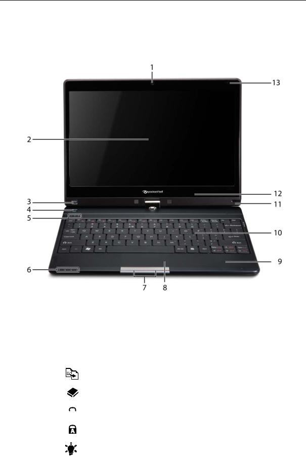
Your Notebook Tour
This section provides an overview of the features and functions of the notebook.
Front View
|
No. |
Icon |
Item |
Description |
|
||
|
|
|
|
|
|
|
|
|
1 |
|
|
|
Webcam |
Web camera for video communication |
|
|
2 |
|
|
|
Display screen |
Also called Liquid-Crystal Display (LCD), displays |
|
|
|
|
|
|
|
computer output (Configuration may vary by |
|
|
|
|
|
|
|
models). |
|
|
|
|
|
|
|
|
|
|
3 |
|
P |
Programmable |
Launch predefined programs or user defined |
|
|
|
|
|
|
|
key |
programs at the push of a button. |
|
|
4 |
|
|
|
Backup key |
Press to start automatic backup procedure. |
|
|
|
|
|
|
|
|
|
|
5 |
|
|
|
HDD |
Indicates when the hard drive is active. |
|
|
|
|
|
|
|
|
|
|
|
|
|
|
Num Lock |
Lights up when the Num Lock is activated. |
|
|
|
|
|
|
|
|
|
|
|
|
|
|
|
|
|
|
|
|
|
|
Caps Lock |
Lights up when Caps Lock is activated. |
|
|
|
|
|
|
|
|
|
|
|
|
|
|
|
|
|
|
6 |
|
|
|
Power |
Indicated the computer’s power status. |
|
|
|
|
|
|
|||
|
|
|
|
|
|||
|
|
|
|
|
|
|
|
|
|
|
|
|
|
|
|
4 |
Chapter 1 |
No. |
Icon |
Item |
Description |
||
|
|
|
|
|
|
|
|
|
|
Battery |
Indicates the computer's battery status. |
|
|
|
|
||
|
|
|
|
|
1. Charging: The light shows amber when the |
|
|
|
|
|
|
|
|
|
|
|
battery is charging. |
|
|
|
|
|
2. Fully charged: The light shows blue when in AC |
|
|
|
|
|
mode. |
|
|
|
|
|
|
|
|
|
|
Bluetooth |
Indicates the status of Bluetooth communication. |
|
|
|
|
communication |
(only for certain models) |
|
|
|
|
indicator |
|
|
|
|
|
|
|
|
|
|
|
Communication |
Indicates the status of WLAN / 3G communication. |
|
|
|
|
indicator |
|
|
|
|
|
|
|
7 |
|
|
|
Click buttons (left |
The left and right buttons function like the left and |
|
|
|
|
and right) |
right mouse buttons. |
|
|
|
|
|
|
8 |
|
|
|
Touchpad |
Touch-sensitive pointing device which functions like |
|
|
|
|
|
a computer mouse. |
|
|
|
|
|
|
9 |
|
|
|
Palmrest |
Comfortable support area for your hands when you |
|
|
|
|
|
use the computer. |
|
|
|
|
|
|
10 |
|
|
|
Keyboard |
For entering data into your computer. |
|
|
|
|
|
|
11 |
|
|
|
Stylus |
A pen tool for entering data into your computer |
|
|
|
|
|
|
12 |
|
|
|
Microphone |
Internal microphone for sound recording |
|
|
|
|
|
|
13 |
|
|
|
Magnetic lock |
A lock that snaps into place to prevent the screen |
|
|
|
|
|
from inadvertently rotating. |
|
|
|
|
|
|
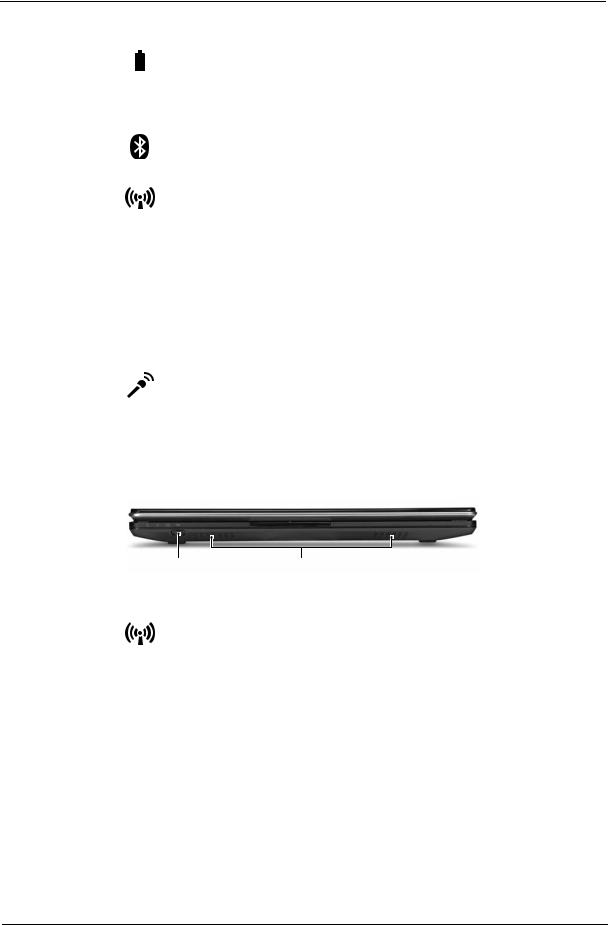
Closed Front View
|
|
|
|
|
|
|
1 |
|
2 |
||
|
|
|
|
|
|
No. |
Icon |
Item |
|
|
Description |
|
|
|
|
|
|
1 |
|
Communication |
|
|
Enables / disables the WLAN / 3G functions. |
|
|
key |
|
|
|
|
|
|
|
|
|
2 |
|
Speakers |
|
|
Left and right speakers deliver stereo audio |
|
|
|
|
|
output. |
|
|
|
|
|
|
Chapter 1 |
5 |

Left View
|
1 |
2 |
3 |
4 |
5 |
||||||
|
|
|
|
|
|
|
|
|
|
|
|
No. |
|
Icon |
Item |
|
|
Description |
|||||
|
|
|
|
|
|
|
|
|
|
||
1 |
|
|
|
|
|
|
|
External display |
Connects to a display device (e.g. external |
||
|
|
|
|
|
|
|
|
(VGA) port |
monitor, LCD projector). |
||
|
|
|
|
|
|
|
|
|
|
||
2 |
|
|
|
|
|
|
|
DC-in jack |
Connects to an AC adapter |
||
|
|
|
|
|
|
|
|||||
|
|
|
|
|
|
|
|||||
|
|
|
|
|
|
|
|
|
|
|
|
3 |
|
|
|
|
|
|
|
Ventilation slots |
Enable the computer to stay cool, even after |
||
|
|
|
|
|
|
|
|
|
prolonged use. |
|
|
|
|
|
|
|
|
|
|
|
|
||
4 |
HDMI |
HDMI port |
Supports high definition digital video |
||||||||
|
|
connections. |
|
||||||||
|
|
|
|
|
|
|
|
|
|
||
5 |
|
|
|
|
|
|
|
USB 2.0 port |
Connect to USB 2.0 devices (e.g., USB mouse, |
||
|
|
|
|
|
|
|
|
|
USB camera). |
|
|
|
|
|
|
|
|
|
|
|
|
|
|
Right View
|
1 |
2 |
3 |
4 |
5 |
6 |
|||
|
|
|
|
|
|
|
|
|
|
No. |
Icon |
|
Item |
|
|
Description |
|||
|
|
|
|
|
|
||||
1 |
|
|
|
Multi-in-1 card |
Accepts Secure Digital (SD), MultiMediaCard |
||||
|
|
|
|
reader |
(MMC), Memory Stick (MS), Memory Stick |
||||
|
|
|
|
|
|
PRO (MS PRO), xD-Picture Card (xD). |
|||
|
|
|
|
|
|
Note: Push to remove/install the card. Only one |
|||
|
|
|
|
|
|
card can operate at any given time. |
|||
|
|
|
|
|
|
||||
2 |
|
|
|
Headphones/ |
Connects to audio line-out devices (e.g., |
||||
|
|
|
|
speaker/line-out |
speakers, headphones). |
||||
|
|
|
|
jack with |
|
|
|
|
|
|
|
|
|
S/PDIF support |
|
|
|
|
|
|
|
|
|
|
|
||||
|
|
|
|
Microphone-in |
Accepts inputs from external microphones. |
||||
|
|
|
|
jack |
|
|
|
|
|
|
|
|
|
|
|
||||
3 |
|
|
|
USB 2.0 port |
Connects to USB 2.0 devices |
||||
|
|
|
|
|
|
(e.g., USB mouse, USB camera). |
|||
|
|
|
|
|
|
||||
4 |
|
|
|
Power button / |
Slide the power button to turn the computer on |
||||
|
|
|
|
indicator |
and off. / Indicates the computer's power |
||||
|
|
|
|
|
|
status. |
|
|
|
|
|
|
|
|
|
|
|
|
|
6 |
Chapter 1 |
5 |
|
Kensington lock |
Connects to a Kensington-compatible |
|
|
slot |
computer security lock. |
|
|
|
Note: Wrap the computer security lock cable |
|
|
|
around an immovable object such as a table or |
|
|
|
handle of a locked drawer. Insert the lock into |
|
|
|
the notch and turn the key to secure the lock. |
|
|
|
Some keyless models are also available. |
|
|
|
|
6 |
|
Ethernet (RJ-45) |
Connects to an Ethernet 10/100/1000-based |
|
|
port |
network. |
|
|
|
|
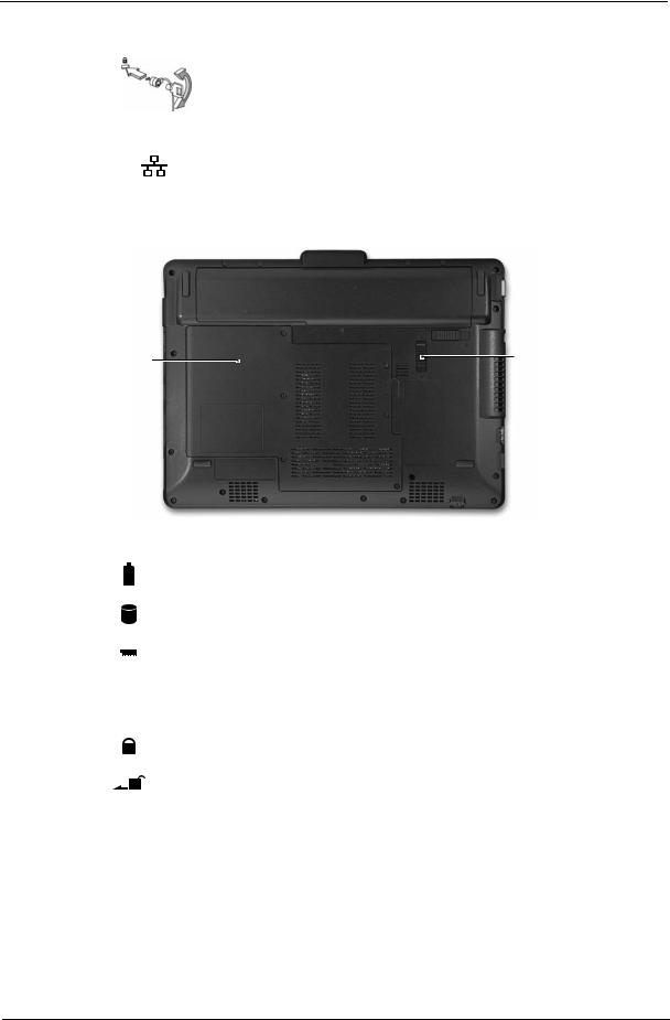
Base View
1 
 6
6
2 |
5 |
|
 4
4
3
No. |
Icon |
Item |
Description |
||||
|
|
|
|
|
|
|
|
1 |
|
|
|
|
|
Battery bay |
Houses the computer's battery pack. |
|
|
|
|
|
|||
|
|
|
|
|
|
|
|
|
|
|
|
|
|
|
|
2 |
|
|
|
|
|
Hard disk bay |
Houses the computer's hard disk (secured with |
|
|
|
|
|
|
|
screws). |
|
|
|
|
|
|
|
|
3 |
|
|
|
|
|
Memory |
Houses the computer's main memory. |
|
|
|
|
|
|
compartment |
|
4 |
|
|
|
|
|
Ventilation slots |
Enable the computer to stay cool, even after |
|
|
|
|
|
|
and cooling fan |
prolonged use. |
|
|
|
|
|
|
|
Note: Do not cover or obstruct the opening of the fan. |
|
|
|
|
|
|
|
|
5 |
|
|
|
|
|
Battery lock |
Locks the battery in position. |
|
|
|
|
|
|
|
|
6 |
|
|
|
|
|
Battery release |
Releases the battery for removal. |
|
|
|
|
|
|
latch |
|
|
|
|
|
|
|
|
|
|
|
|
|
|
|
|
|
Chapter 1 |
7 |

Rear View
|
|
|
|
|
1 |
|
|
|
|
|
|
No. |
Icon |
Item |
Description |
||
|
|
|
|
|
|
1 |
|
|
|
Battery bay |
Houses the computer's battery pack. |
|
|
|
|||
|
|
|
|
|
|
|
|
|
|
|
|
Indicators
The computer has several easy-to-read status indicators. The battery indicator is visible even when the computer cover is closed.
Icon |
Function |
Description |
||
|
|
|
|
|
|
|
|
Bluetooth |
Indicates the status of Bluetooth communication. |
|
|
|
|
|
|
|
|
Wireless LAN |
Indicates the status of Wireless LAN/3G communication. |
|
|
|
|
|
|
|
|
HDD |
Indicates when the hard disk drive is active. |
|
|
|
|
|
|
|
|
Num Lock |
Lights up when Num Lock is activated. |
|
|
|
|
|
|
|
|
|
|
|
|
|
Caps Lock |
Lights up when Caps Lock is activated. |
|
|
|
|
|
|
|
|
Battery |
Indicates the computer's battery status. |
|
|
|
|
|
NOTE: 1. Charging: The battery light shows amber when the battery is charging. 2. Fully charged: The light shows green when in AC mode.
8 |
Chapter 1 |

TouchPad Basics
The following items show you how to use the TouchPad:
1
2 |
3 |
•Move your finger across the TouchPad (1) to move the cursor.
•Press the left (2) and right (3) buttons located beneath the TouchPad to perform selection and execution functions. These two buttons are similar to the left and right buttons on a mouse. Tapping on the TouchPad is the same as clicking the left button.
Function |
Left Button (2) |
Right Button (3) |
Main TouchPad (1) |
|
|
|
|
Execute |
Quickly click twice. |
|
Tap twice (at the same speed |
|
|
|
as double-clicking a mouse |
|
|
|
button). |
|
|
|
|
Select |
Click once. |
|
Tap once. |
|
|
|
|
Drag |
Click and hold, then use |
|
Tap twice (at the same speed |
|
finger on the TouchPad to |
|
as double-clicking a mouse |
|
drag the cursor. |
|
button); rest your finger on |
|
|
|
the TouchPad on the second |
|
|
|
tap and drag the cursor. |
|
|
|
|
Access |
|
Click once. |
|
context menu |
|
|
|
|
|
|
|
NOTE: When using the TouchPad, keep it - and your fingers - dry and clean. The TouchPad is sensitive to finger movement; hence, the lighter the touch, the better the response. Tapping too hard will not increase the TouchPad’s responsiveness.
Chapter 1 |
9 |

Using the Keyboard
This computer has a close-to-full-sized keyboard and an embedded numeric keypad, separate cursor, lock, function and special keys.
Lock Keys and embedded numeric keypad
The keyboard has three lock keys which you can toggle on and off.
Lock key |
Description |
|
|
Caps Lock |
When Caps Lock is on, all alphabetic characters typed are in uppercase. |
Num Lock |
When Num Lock is on, the embedded keypad is in numeric mode. The keys |
<Fn> + <F11> |
function as a calculator (complete with the arithmetic operators +, -, *, and /). Use |
|
this mode when you need to do a lot of numeric data entry. A better solution |
|
would be to connect an external keypad. |
|
|
Scroll Lock <Fn> + |
When Scroll Lock is on, the screen moves one line up or down when you press |
<F12> |
the up or down arrow keys respectively. Scroll Lock does not work with some |
|
applications. |
|
|
The embedded numeric keypad functions like a desktop numeric keypad. It is indicated by small characters located on the upper right corner of the keycaps. To simplify the keyboard legend, cursor-control key symbols are not printed on the keys.
Desired access |
Num Lock on |
Num Lock off |
|
|
|
Number keys on |
Type numbers in a normal manner. |
|
embedded keypad |
|
|
|
|
|
Cursor-control keys on |
Hold <Shift> while using cursor- |
Hold <Fn> while using cursor- |
embedded keypad |
control keys. |
control keys. |
|
|
|
Main keyboard keys |
Hold <Fn> while typing letters on |
Type the letters in a normal |
|
embedded keypad. |
manner. |
|
|
|
10 |
Chapter 1 |
Windows Keys
The keyboard has two keys that perform Windows-specific functions.
|
|
|
Key |
Description |
|
|
|
|
|
|
|
|
Windows key |
Pressed alone, this key has the same effect as clicking on the Windows Start button; |
|
|
|
|
it launches the Start menu. It can also be used with other keys to provide a variety of |
|
|
|
|
functions: |
|
|
|
|
< >: Open or close the Start menu |
|
|
|
|
< > + <D>: Display the desktop |
|
|
|
|
< > + <E>: Open Windows Explore |
|
|
|
|
< > + <F>: Search for a file or folder |
|
|
|
|
< > + <L>: Lock your computer (if you are connected to a network domain), or |
|
|
|
|
switch users (if you're not connected to a network domain) |
|
|
|
|
< > + <M>: Minimizes all windows |
|
|
|
|
< > + <R>: Open the Run dialog box |
|
|
|
|
< > + <U>: Open Ease of Access Center |
|
|
|
|
< > + <BREAK>: Display the System Properties dialog box |
|
|
|
|
< > + <TAB>: Cycle through programs on the taskbar |
|
|
|
|
<CTRL> + < > + <F>: Search for computers (if you are on a network) |
|
|
|
|
Note: Depending on your edition of Windows 7, some shortcuts may not function as |
|
|
|
|
described. |
|
|
|
|
|
|
|
|
Application |
This key has the same effect as clicking the right mouse button; it opens the |
|
|
|
||
|
|
|
key |
application's context menu. |
|
|
|
||
|
|
|
|
|
Chapter 1 |
11 |
Hot Keys
The computer employs hotkeys or key combinations to access most of the computer's controls like screen brightness and volume output.
To activate hotkeys, press and hold the <Fn> key before pressing the other key in the hotkey combination.
Hotkey |
Icon |
Function |
Description |
|
<Fn> + <F1> |
|
Power management |
Launch Windows power management. |
|
<Fn> + <F2> |
|
System Properties |
Display the System Properties dialog box. |
|
<Fn> + <F3> |
|
Bluetooth |
Enables/disables the Bluetooth function. |
|
|
|
|
communication switch |
|
<Fn> + <F4> |
|
Sleep |
Puts the computer in Sleep mode. |
|
<Fn> + <F5> |
|
Display toggle |
Switches display output between the display |
|
|
|
|
|
screen, external monitor (if connected) and |
|
|
|
|
both. |
<Fn> + <F6> |
|
Screen blank |
Turns the display screen backlight off to save |
|
|
|
|
|
power. Press any key to return. |
<Fn> + <F7> |
|
Touchpad toggle |
Turns the internal touchpad on and off. |
|
<Fn> + <F8> |
|
Speaker toggle |
Turns the speakers on and off. |
|
<Fn> + < |
> |
|
Brightness up |
Increases the screen brightness. |
<Fn> + < |
> |
|
Brightness down |
Decreases the screen brightness. |
<Fn> + < |
> |
|
Volume up |
Increases the sound volume. |
<Fn> + < |
> |
|
Volume down |
Decreases the sound volume. |
12 |
Chapter 1 |

Special Keys
You can locate the Euro symbol and the US dollar sign at the upper-center and/or bottom-right of your keyboard.
The Euro symbol
1.Open a text editor or word processor.
2.Hold <Alt Gr> and then press the <5> key at the upper-center of the keyboard.
NOTE: Some fonts and software do not support the Euro symbol. See www.microsoft.com/typography/faq/ faq12.htm for more information.
The US dollar sign
1.Open a text editor or word processor.
2.Hold <Shift> and then press the <4> key at the upper-center of the keyboard. NOTE: This function varies according to the language settings.
Chapter 1 |
13 |

Hardware Specifications and Configurations
Processor
|
|
Item |
|
|
|
|
|
|
|
Specification |
|
|
|
||
|
|
|
|
|
|
|
|
|
|
|
|
|
|
|
|
CPU type |
|
|
|
|
|
Intel Penryn SFF (ULV) |
|
|
|
|
|
||||
|
|
|
|
|
|
|
|
|
|
|
|
|
|
||
CPU package |
|
|
|
|
Micro-FCBGA 956 balls |
|
|
|
|
|
|||||
|
|
|
|
|
|
|
|
|
|
|
|
|
|
||
Features |
|
|
|
|
|
• Supports Intel architecture with Dynamic execution. |
|||||||||
|
|
|
|
|
|
|
• On-die, primary 32-kB instruction cache and 32-kB write-back |
||||||||
|
|
|
|
|
|
|
|
data cache. |
|
|
|
|
|
||
|
|
|
|
|
|
|
• On-die, up to 3MB second level shared cache with advanced |
||||||||
|
|
|
|
|
|
|
|
transfer cache architecture. |
|
|
|
||||
|
|
|
|
|
|
|
• Streaming SIMD Extensions 2 (SSE2),Streaming SIMD |
||||||||
|
|
|
|
|
|
|
|
Extensions 3 (SSE3) |
|
|
|
|
|
||
|
|
|
|
|
|
|
• Supplemental streaming SIMD extensions 3 (SSSE3) and |
||||||||
|
|
|
|
|
|
|
|
SSE4.1 instruction sets. |
|
|
|
||||
|
|
|
|
|
|
|
• 800MHz source-synchronous front side bus (FSB) |
||||||||
|
|
|
|
|
|
|
• Advanced power management features including Enhanced |
||||||||
|
|
|
|
|
|
|
|
Intel SpeedStep® |
|
|
|
|
|
||
|
|
|
|
|
|
|
• Technology and dynamic FSB frequency switching. |
||||||||
|
|
|
|
|
|
|
• Digital thermal sensor (DTS). |
|
|
|
|||||
|
|
|
|
|
|
|
• Execute disable bit support for enhanced security. |
||||||||
|
|
|
|
|
|
|
• Intel® Dynamic Acceleration Technology and Enhanced Multi |
||||||||
|
|
|
|
|
|
|
|
Threaded |
|
|
|
|
|
||
|
|
|
|
|
|
|
• Thermal Management (EmTTM). |
|
|
|
|||||
|
|
|
|
|
|
|
• Support enhanced Intel Virtualization Technology. |
||||||||
|
|
|
|
|
|
|
|
|
|
|
|
|
|
||
Core Logic |
|
|
|
|
|
• Mobile Intel® GS45 Express Chipset |
|
|
|
||||||
|
|
|
|
|
|
|
|
|
|
|
|
|
|
|
|
Processor Specifications |
|
|
|
|
|
|
|
|
|
|
|||||
|
|
|
|
|
|
|
|
|
|
|
|
|
|
|
|
Item |
|
CPU |
Cores |
|
Cache |
|
Package |
|
Core |
Acer P/N |
|
||||
|
Speed |
|
|
Size |
|
|
Voltage |
|
|||||||
|
|
|
|
|
|
|
|
|
|
|
|
|
|||
|
|
|
|
|
|
|
|
|
|
|
|
|
|
|
|
SU7300 |
|
1.4GHz |
1 |
|
|
3MB |
|
Micro-FCBGA 956 |
|
1.050V- |
C2DSU7300B |
|
|||
|
|
|
|
|
|
|
|
|
balls |
|
1.150V |
|
|
|
|
|
|
|
|
|
|
|
|
|
|
|
|
|
|
|
|
SU4100 |
|
1.3GHz |
2 |
|
|
2MB |
|
Micro-FCBGA 956 |
|
1.050V- |
PMDSU4100B |
|
|||
|
|
|
|
|
|
|
|
|
balls |
|
1.150V |
|
|
|
|
|
|
|
|
|
|
|
|
|
|
|
|
|
|
|
|
SU2300 |
|
1.2GHz |
2 |
|
|
1MB |
|
Micro-FCBGA 956 |
|
1.050V- |
CMSU2300B |
|
|||
|
|
|
|
|
|
|
|
|
balls |
|
1.150V |
|
|
|
|
|
|
|
|
|
|
|
|
|
|
|
|
|
|
|
|
CPU Fan True Value Table |
|
|
|
|
|
|
|
|
|
|
|||||
|
|
|
|
|
|
|
|
|
|
|
|
|
|
|
|
CPU Temperature |
|
|
|
Fan Speed (RPM) |
|
SPL Spec (dBA) |
|
|
|||||||
(Celsius) |
|
|
|
|
|
|
|||||||||
|
|
|
|
|
|
|
|
|
|
|
|
|
|||
|
|
|
|
|
|
|
|
|
|
|
|
|
|||
38 |
|
|
|
2400 |
|
|
|
|
On |
|
|
|
|||
|
|
|
|
|
|
|
|
|
|
|
|
|
|
||
43 |
|
|
|
3300 |
|
|
|
|
26 |
|
|
|
|
|
|
|
|
|
|
|
|
|
|
|
|
|
|
|
|
||
49 |
|
|
|
4000 |
|
|
|
|
29 |
|
|
|
|
|
|
|
|
|
|
|
|
|
|
|
|
|
|
|
|
||
56 |
|
|
|
4500 |
|
|
|
|
31 |
|
|
|
|
|
|
|
|
|
|
|
|
|
|
|
|
||||||
Throttling 50%: On = 88°C; Off = 85°C |
|
|
|
|
|
|
|
|
|||||||
EC shut down at 95°C; H/W shut down at 98°C |
|
|
|
|
|
||||||||||
North Bridge Specifications |
|
|
|
|
|
|
|
|
|
|
|||||
|
|
|
|
|
|
|
|
|
|
|
|
|
|
|
|
|
|
Item |
|
|
|
|
|
|
|
Specification |
|
|
|
||
|
|
|
|
|
|
|
|
|
|
|
|
||||
Chipset |
|
|
|
|
|
Intel Crestline GS45 SFF |
|
|
|
|
|
||||
Package |
|
|
|
|
|
FCBGA 1363 balls |
|
|
|
|
|
||||
|
|
|
|
|
|
|
|
|
|
|
|
|
|
|
|
14 |
Chapter 1 |

|
Item |
|
|
|
|
|
Specification |
|
|
|||
|
|
|
|
|
|
|
|
|
|
|||
Features |
|
|
|
• Processor host bus supports 667/800/1066Mhz FSB support. |
|
|||||||
|
|
|
|
• Supports Dual Channel DDR3 SD-RAM at 800/1066MHz. |
|
|||||||
|
|
|
|
• Integrated SDRAM controller up to *GB (2 SODIMM support) |
|
|||||||
|
|
|
|
• DMI x2 and DMI x4 for connection between GMCH and |
|
|||||||
|
|
|
|
|
ICH9M. |
|
|
|
|
|
|
|
|
|
|
|
|
|
|
|
|
|
|
|
|
South Bridge Specifications |
|
|
|
|
|
|
|
|
|
|
||
|
|
|
|
|
|
|
|
|
|
|
|
|
|
Item |
|
|
|
|
|
Specification |
|
|
|||
|
|
|
|
|
|
|
|
|
|
|
|
|
Chipset |
|
|
|
ICH9M SFF |
|
|
|
|
|
|
||
|
|
|
|
|
|
|
|
|
|
|
|
|
Package |
|
|
|
BGA 676 balls |
|
|
|
|
|
|
||
|
|
|
|
|
|
|
|
|
|
|||
Features |
|
|
|
• Upstream accelerated Hub architecture interface for access to |
|
|||||||
|
|
|
|
|
GMCH. |
|
|
|
|
|
|
|
|
|
|
|
• PCI Express Base Specification, Revision 1.1 support. |
|
|||||||
|
|
|
|
• PCI 2.3 interface. (4 PCI Request/Grant pairs). |
|
|
||||||
|
|
|
|
• |
ACPI Power Management Logic Support. Enhanced DMA |
|
||||||
|
|
|
|
|
controller, interrupt controller, timers functions. |
|
|
|||||
|
|
|
|
• Integrated Serial ATA host controllers with independent DMA |
|
|||||||
|
|
|
|
|
operation on six ports and AHCI support. |
|
|
|||||
|
|
|
|
• USB 1.1 & USB 2.0 Host controllers. |
|
|
||||||
|
|
|
|
• Supports Intel High Definition Audio (Intel HD Audio) Interface. |
|
|||||||
|
|
|
|
• Supports Intel® Matrix Storage Technology. |
|
|
||||||
|
|
|
|
• Supports Intel® Active Management Technology. |
|
|
||||||
|
|
|
|
• Low Pin Count (LPC) interface. |
|
|
|
|
||||
|
|
|
|
• |
6 PCIe ports. |
|
|
|
|
|
|
|
|
|
|
|
|
|
|
|
|
|
|
|
|
System Memory |
|
|
|
|
|
|
|
|
|
|
||
|
|
|
|
|
|
|
|
|
|
|
|
|
|
Item |
|
|
|
|
|
Specification |
|
|
|||
|
|
|
|
|
|
|
|
|
|
|
||
Memory size |
|
|
|
0MB (No on-board Memory) |
|
|
|
|
||||
DIMM socket number |
|
2 sockets |
|
|
|
|
|
|
||||
|
|
|
|
|
|
|
|
|
|
|
|
|
Supports memory size per socket |
2GB |
|
|
|
|
|
|
|
|
|||
|
|
|
|
|
|
|
|
|
|
|||
Supports maximum memory size |
4GB for 64bit OS (with two 2GB SO-DIMM) |
|
|
|||||||||
|
|
|
|
|
|
|
|
|
|
|
||
Supports DIMM type |
|
DDR3 Synchronous DRAM |
|
|
|
|
||||||
|
|
|
|
|
|
|
|
|
|
|
|
|
Supports DIMM Speed |
|
800 MHz |
|
|
|
|
|
|
||||
|
|
|
|
|
|
|
|
|
|
|
|
|
Supports DIMM voltage |
|
1.5V |
|
|
|
|
|
|
||||
|
|
|
|
|
|
|
|
|
|
|
||
Supports DIMM package |
|
204-pin DDR3-800 SO-DIMM |
|
|
|
|
||||||
|
|
|
|
|
|
|
|
|
|
|||
Module Combination |
|
Any combination permissible within the above specifications. |
|
|||||||||
|
|
|
|
|
|
|
|
|
|
|
|
|
Hard Disk Drive Interface |
|
|
|
|
|
|
|
|
|
|
||
|
|
|
|
|
|
|
|
|
|
|
|
|
Item |
|
|
|
Specifications |
|
|
|
|
|
|
||
|
|
|
|
|
|
|
|
|
|
|
|
|
Vendor & |
Hitachi |
|
Hitachi |
|
Hitachi |
|
Hitachi |
Hitachi |
|
Hitachi |
|
|
Model |
HTS545050B |
|
HTS545032B |
|
HTS545025B |
|
HTS545016B |
HTS543225L |
|
HTS543216L9 |
|
|
Name |
9A300 |
|
9A300 |
|
|
9A300 |
|
9A300 |
9A300 |
|
SA00 |
|
|
|
|
|
|
|
|
|
|
|
|
|
|
Capacity |
500 |
|
320 |
|
|
250 |
|
160 |
250 |
|
160 |
|
(GB) |
|
|
|
|
|
|
|
|
|
|
|
|
|
|
|
|
|
|
|
|
|
|
|
|
|
Bytes per |
|
|
|
|
|
|
512 |
|
|
|
|
|
sector |
|
|
|
|
|
|
|
|
|
|
|
|
|
|
|
|
|
|
|
|
|
|
|
|
|
Data heads |
4 |
|
3 |
|
|
2 |
|
2 |
3 |
|
2 |
|
|
|
|
|
|
|
|
|
|
|
|
|
|
Drive Format |
|
|
|
|
|
|
|
|
|
|
|
|
|
|
|
|
|
|
|
|
|
|
|
|
|
Chapter 1 |
15 |

Item |
|
|
|
Specifications |
|
|
|
|
|
|
|
|
|
|
|
|
|
|
|
Disks |
2 |
|
2 |
|
1 |
|
1 |
2 |
1 |
Spindle |
|
|
|
|
|
5400 |
|
|
|
speed |
|
|
|
|
|
|
|
|
|
(RPM) |
|
|
|
|
|
|
|
|
|
|
|
|
|
|
|
|
|
|
|
Performance Specifications |
|
|
|
|
|
|
|||
|
|
|
|
|
|
|
|
|
|
Buffer size |
|
|
|
|
|
8MB |
|
|
|
|
|
|
|
|
|
|
|
|
|
Interface |
|
|
|
|
|
SATA |
|
|
|
|
|
|
|
|
|
|
|||
Internal |
|
|
|
3GB/s maximum |
|
1.5GB/s |
|||
transfer |
|
|
|
|
|
|
|
|
maximum |
rate (Gbits/ |
|
|
|
|
|
|
|
|
|
sec., max) |
|
|
|
|
|
|
|
|
|
|
|
|
|
|
|
|
|||
I/O data |
|
875 Mbits/s maximum |
|
845 Mbits/s |
775Mbits/s |
729Mbits/s |
|||
transfer |
|
|
|
|
|
|
maximum |
maximum |
maximum |
rate |
|
|
|
|
|
|
|
|
|
(Mbytes/ |
|
|
|
|
|
|
|
|
|
sec max) |
|
|
|
|
|
|
|
|
|
|
|
|
|
|
|
|
|
|
|
DC Power Requirements |
|
|
|
|
|
|
|
|
|
|
|
|
|
|
|
|
|
|
|
Voltage |
|
|
|
|
|
+5.0V ± 5%. |
|
|
|
|
|
|
|
|
|
|
|
|
|
Item |
|
|
Specifications |
|
|
|
|
|
|
|
|
Vendor & Model |
Toshiba |
Toshiba |
|
Toshiba |
Toshiba |
Name |
MK1655GSX |
MK2555GSX |
|
MK3255GSX |
MK5055GSX |
|
|
|
|
|
|
|
|
|
|
|
|
Capacity (GB) |
160 |
250 |
|
320 |
500 |
|
|
|
|
|
|
Bytes per sector |
512 |
512 |
|
512 |
512 |
|
|
|
|
|
|
Data heads |
2 |
2 |
|
4 |
4 |
|
|
|
|
|
|
Drive Format |
|
|
|
|
|
|
|
|
|
|
|
Disks |
1 |
1 |
|
2 |
2 |
|
|
|
|
|
|
Spindle speed |
|
|
5400 |
|
|
(RPM) |
|
|
|
|
|
|
|
|
|
|
|
Performance Specifications |
|
|
|
|
|
|
|
|
|
|
|
Buffer size |
|
|
8MB |
|
|
|
|
|
|
|
|
Interface |
|
|
SATA |
|
|
|
|
|
|
|
|
Internal transfer |
|
|
363 ~ 952 typical |
|
|
rate (Mbits/sec, |
|
|
|
|
|
max) |
|
|
|
|
|
|
|
|
|
|
|
I/O data transfer |
|
|
300 |
|
|
rate |
|
|
|
|
|
(Mbytes/sec |
|
|
|
|
|
max) |
|
|
|
|
|
|
|
|
|
|
|
DC Power Requirements |
|
|
|
|
|
|
|
|
|
|
|
Voltage |
|
|
5V ±5% |
|
|
|
|
|
|
|
|
Item |
|
Specifications |
|
||
|
|
|
|
|
|
Vendor & Model |
Western Digital |
Western Digital |
|
Western Digital |
Western Digital |
Name |
WD1600BEVT- |
WD2500BEVT-22ZCT0 |
|
WD3200BEVT-22ZCT0 |
WD5000BEVT-22ZAT0 |
22ZCTO |
|
|
|
|
|
|
|
|
|
|
|
|
|
|
|
|
|
Capacity (GB) |
160 |
250 |
|
320 |
500 |
|
|
|
|
|
|
Bytes per sector |
|
|
512 |
|
|
|
|
|
|
|
|
Data heads |
2 |
4 |
|
3 |
4 |
|
|
|
|
|
|
16 |
Chapter 1 |

Item |
|
|
|
|
Specifications |
|
|
|
|
|
|
|
|
|
|
|
|
|
|
|
|
|
|
Drive Format |
|
|
|
|
|
|
|
|
|
|
|
Disks |
|
1 |
|
2 |
|
2 |
|
2 |
|
|
|
|
|
|
|
|
|
|
|
|
|
|
|
Spindle speed |
|
|
|
|
5400 |
|
|
|
|
|
|
(RPM) |
|
|
|
|
|
|
|
|
|
|
|
|
|
|
|
|
|
|
|
|
|
|
|
Performance Specifications |
|
|
|
|
|
|
|
|
|
||
|
|
|
|
|
|
|
|
|
|
|
|
Buffer size |
|
|
|
|
8 MB |
|
|
|
|
|
|
|
|
|
|
|
|
|
|
|
|
|
|
Interface |
|
|
|
|
SATA |
|
|
|
|
|
|
|
|
|
|
|
|
|
|
|
|
|
|
Internal transfer |
|
|
|
|
N/A |
|
|
|
|
|
|
rate (Mbits/sec, |
|
|
|
|
|
|
|
|
|
|
|
max) |
|
|
|
|
|
|
|
|
|
|
|
|
|
|
|
|
|
|
|
|
|
|
|
I/O data transfer |
|
|
|
|
300 |
|
|
|
|
|
|
rate |
|
|
|
|
|
|
|
|
|
|
|
(Mbytes/sec |
|
|
|
|
|
|
|
|
|
|
|
max) |
|
|
|
|
|
|
|
|
|
|
|
|
|
|
|
|
|
|
|
|
|
|
|
DC Power Requirements |
|
|
|
|
|
|
|
|
|
||
|
|
|
|
|
|
|
|
|
|
|
|
Voltage |
|
|
|
|
5V ±5% |
|
|
|
|
|
|
|
|
|
|
|
|
|
|
|
|
|
|
BIOS |
|
|
|
|
|
|
|
|
|
|
|
|
|
|
|
|
|
|
|
|
|
|
|
Item |
|
|
|
|
Specification |
|
|
|
|||
|
|
|
|
|
|
|
|
|
|
||
BIOS vendor |
|
Insyde |
|
|
|
|
|
|
|
||
|
|
|
|
|
|
|
|
|
|||
BIOS ROM type |
|
W25X16AVSSIG |
|
|
|
|
|
||||
|
|
|
|
|
|
|
|
|
|
||
BIOS ROM size |
|
16Mb |
|
|
|
|
|
|
|
||
|
|
|
|
|
|
|
|
|
|
||
BIOS package |
|
8 PIN SOIC |
|
|
|
|
|
|
|
||
|
|
|
|
|
|
|
|
|
|
||
Supported Protocols |
|
SPI |
|
|
|
|
|
|
|
||
|
|
|
|
|
|
|
|
||||
BIOS password control |
Set by setup manual |
|
|
|
|
|
|||||
|
|
|
|
|
|
|
|
|
|
|
|
LCD 11.6” |
|
|
|
|
|
|
|
|
|
|
|
|
|
|
|
|
|
|
|
|
|
|
|
Item |
|
|
|
|
Specifications |
|
|
|
|||
|
|
|
|
|
|
|
|||||
Vendor/model name |
|
AUO |
Chi Mei |
LG |
Samsung |
|
|||||
|
|
|
B116XW02 |
N116B6-L02 |
LP116WH1 |
LTN116AT01- |
|
||||
|
|
|
|
|
|
|
|
|
A01 |
|
|
|
|
|
|
|
|
|
|
|
|||
Screen Diagonal (mm) |
|
|
293.83 |
|
|
|
|
||||
|
|
|
|
|
|
|
|
||||
Active Area (mm) |
|
|
|
256.125 (H) x 144.00 (V) |
|
|
|
||||
|
|
|
|
|
|
|
|||||
Display resolution (pixels) |
|
|
1366x3(RGB) x 768 |
|
|
|
|||||
|
|
|
|
|
|
|
|
|
|||
Pixel Pitch (mm) |
|
|
|
0.1875 x 0.1875 |
|
|
0.2265(H) x |
|
|||
|
|
|
|
|
|
|
|
|
0.2265(V) |
|
|
|
|
|
|
|
|
|
|||||
Typical White Luminance (cd/m2) |
|
|
200 typ. (5 points average) |
|
|
|
|||||
also called Brightness |
|
|
|
|
|
|
|
|
|
||
Contrast Ratio |
|
|
|
|
500:1 typ |
|
|
|
|||
|
|
|
|
|
|
||||||
Response Time (Optical Rise |
8 typ / 16 |
8 typ / 16 Max |
9 typ / 16 max |
16 typ / 25 |
|
||||||
Time/Fall Time) msec |
|
Max |
|
|
|
|
max |
|
|||
|
|
|
|
|
|
||||||
Typical Power Consumption |
4.0 max. |
N/A |
3.18 W Typ. |
N/A |
|
||||||
(watt) |
|
(Include |
|
|
|
|
|
|
|
||
|
|
|
Logic and |
|
|
|
|
|
|
|
|
|
|
|
Blu power) |
|
|
|
|
|
|
|
|
|
|
|
|
|
|
||||||
Weight (without inverter) |
255g max. |
240g max |
255g max. |
|
|||||||
|
|
|
|
|
|
|
|
|
|||
Physical Size (mm) |
|
|
|
268L x 161.5W x 5.0T |
|
|
|
||||
|
|
|
|
|
|
|
|
|
|
|
|
Chapter 1 |
17 |

Item |
|
|
|
|
|
Specifications |
|
|
|
|||
|
|
|
|
|
|
|
|
|
|
|
|
|
Electrical Interface |
|
|
|
1 channel |
|
3.3V LVDS |
|
LVDS |
LVDS |
|
||
|
|
|
|
|
LVDS |
|
|
|
|
|
|
|
|
|
|
|
|
|
|
|
|
|
|
|
|
Viewing Angle (degree) |
|
|
|
|
|
|
|
|
|
|
||
Horizontal (Right) / (Left) |
|
|
45/45 |
|
45/45 |
|
30/30 |
45/45 |
|
|
||
Vertical (Upper) / (Lower) |
|
|
10/30 |
|
20/45 |
|
10/20 |
15/35 |
|
|
||
|
|
|
|
|
|
|
|
|
|
|
|
|
Bluetooth |
|
|
|
|
|
|
|
|
|
|
|
|
|
|
|
|
|
|
|
|
|
|
|
|
|
Item |
|
|
|
|
|
Specification |
|
|
|
|
||
|
|
|
|
|
|
|
|
|
|
|
||
Bluetooth Controller |
|
|
Foxconn T60H928.33 |
|
|
|
|
|
|
|||
|
|
|
|
|
|
|||||||
Features |
|
|
• Fully Qualified Bluetooth v2.1 with Class 2 specification RF output |
|
|
|||||||
|
|
|
|
power. |
|
|
|
|
|
|
||
|
|
|
|
• Enhanced Data Rate (EDR) compliant. |
|
|
|
|
||||
|
|
|
|
• Full Piconet and Scatternet operation. |
|
|
|
|
||||
|
|
|
|
• Integrated PIFA Antenna with better RF performance. |
|
|
|
|||||
|
|
|
|
• USB 2.0 compliant interface. |
|
|
|
|
||||
|
|
|
|
• F/W upgradable via Flash downloads. |
|
|
|
|
||||
|
|
|
|
• Very low power consumption. |
|
|
|
|
||||
|
|
|
|
• Support Coexistence with Intel WCS (Wireless Coexistence System) |
|
|||||||
|
|
|
|
& AFH (Adaptive Frequency Hopping) |
|
|
|
|
||||
|
|
|
|
|
|
|
|
|
|
|
||
Radio Technology |
|
|
FHSS |
|
|
|
|
|
|
|||
|
|
|
|
|
|
|
|
|
|
|
||
Operating Frequency |
|
|
2.402GHz ~ 2.480GHz |
|
|
|
|
|
|
|||
|
|
|
|
|
|
|
|
|
||||
Channel Numbers |
|
|
79 channels with 1MHz BW |
|
|
|
|
|||||
|
|
|
|
|
|
|
||||||
Transmitter Output Power |
|
-6~4dBm output power for BT class 2 operation |
|
|
|
|||||||
|
|
|
|
|
|
|
|
|||||
Coverage |
|
|
10m (Varies depending on operating environment) |
|
|
|
||||||
|
|
|
|
|
|
|
|
|
|
|
||
Receiver Sensitivity |
|
|
-75dBm, BER<0.1% |
|
|
|
|
|
|
|||
|
|
|
|
|
|
|
|
|
|
|||
Maximum Receiver Signal |
|
-10dBm |
|
|
|
|
|
|
||||
|
|
|
|
|
|
|
|
|
|
|
||
Operating Voltage |
|
|
3.3V+/-0.3V |
|
|
|
|
|
|
|||
|
|
|
|
|
|
|
|
|||||
Working Temperature |
|
|
Operating temp: 0 °C to +70 °C (+32 °F to +158 °F) |
|
|
|
||||||
|
|
|
|
Non-operating temp: -10 °C to +75°C (+14 °F to +167 °F) |
|
|
|
|||||
|
|
|
|
|
|
|
|
|||||
Interface |
|
|
USB2.0 with JST SM08B-SURS-TF connector |
|
|
|
||||||
|
|
|
|
|
|
|
|
|
|
|
||
Weight |
|
|
1.75g |
|
|
|
|
|
|
|||
|
|
|
|
|
|
|
|
|
|
|
|
|
Audio Interface |
|
|
|
|
|
|
|
|
|
|
|
|
|
|
|
|
|
|
|
|
|
|
|
|
|
Item |
|
|
|
|
|
|
Specification |
|
|
|
|
|
|
|
|
|
|
|
|
|
|
||||
Codec Controller |
|
Realtek ALC269X |
|
|
|
|
|
|
||||
|
|
|
|
|
|
|
|
|
|
|
||
Compatibility |
|
|
• |
Headphone-out |
|
|
|
|
|
|
||
|
|
|
• S/PDIF, Line-In and Microphone-In. |
|
|
|
|
|||||
|
|
|
• 2 stereo ADCs support 16/20/24-bit PCM format recording simultaneously. |
|||||||||
|
|
|
|
|||||||||
Sampling Rate |
|
|
• All DACs supports 16/20/24-bit, 44.1k/48k/96k/192kHz sample rate. |
|||||||||
|
|
|
• Two independent S/PDIF-OUT converters support 16/20/24-bit, 44.1k/48k/ |
|||||||||
|
|
|
|
88.2k/96k/192kHz sample rate. One for normal S/PDIF output, the other one |
||||||||
|
|
|
|
output an independent digital stream to HDMI transmitter. |
|
|
|
|||||
|
|
|
|
|
|
|
||||||
Internal |
|
|
• Digital MICRO PHONE ZK2(HFM-M101-006-L19-G) |
|
|
|
||||||
Microphone |
|
|
• |
Digital MICRO PHONE ZK2(A-OA2408FM-018) |
|
|
|
|||||
|
|
|
|
|
|
|
|
|||||
Internal Speakers |
|
|
• Two Med-High Speakers (1W/4Ù) |
|
|
|
|
|||||
|
|
|
|
|
|
|
|
|
|
|
|
|
18 |
Chapter 1 |

LAN Interface
Item |
|
|
|
Specification |
|
|
|
|
|
|
|
LAN Chipset |
|
|
Atheros AR8131L |
||
Package |
|
|
48pin QFN |
||
|
|
|
|
|
|
Features |
|
|
• |
It is an ultra-high performance, ultralow cost, and ultra- |
|
|
|
|
|
low power fully integrated 10/100/1000 Mbps NIC/LOM |
|
|
|
|
|
Ethernet. |
|
|
|
|
• The AR8131L combines a 10/100/1000BASE-T GbE |
||
|
|
|
|
media access controller (MAC), a triplespeed Ethernet |
|
|
|
|
|
physical layer transceiver (PHY), and a PCI Express bus |
|
|
|
|
|
interface. |
|
|
|
|
• The AR8131L is compliant with IEEE 802.3u |
||
|
|
|
|
specification for 10/100 Mbps Ethernet and IEEE |
|
|
|
|
|
802.3ab specification for 1000 Mbps Ethernet. |
|
|
|
|
• The AR8131L device combines pulse shaping, Tx/Rx |
||
|
|
|
|
PCS, echo canceller, NEXT canceller, equalizer, |
|
|
|
|
|
decoder, and timing recovery functions to deliver robust |
|
|
|
|
|
signal performance in noisy environments. |
|
|
|
|
• The AR8131L GbE controller supports checksum off-load |
||
|
|
|
|
features for IP, TCP, and UDP, lowering CPU utilization |
|
|
|
|
|
and optimizing network performance. |
|
|
|
|
|
|
|
Keyboard |
|
|
|
|
|
|
|
|
|
|
|
Item |
|
|
|
Specification |
|
|
|
|
|
|
|
Keyboard Controller |
|
|
|
Winbond WPCE775LA0DG |
|
|
|
|
|
|
|
Total number of keypads |
|
|
|
US: 86 |
|
|
|
|
|
UK: 86 |
|
|
|
|
|
UI: 86 |
|
|
|
|
|
GERMAN: 86 |
|
|
|
|
|
|
|
Windows logo key |
|
|
|
Yes |
|
|
|
|
|
|
|
Internal & external keyboard work |
|
|
Plug USB keyboard to the USB port directly: Yes |
||
simultaneously |
|
|
|
|
|
|
|
|
|
|
|
Features |
|
|
|
• Plug USB keyboard to the USB port directly: Yes |
|
|
|
|
|
|
|
Media Card Reader |
|
|
|
|
|
|
|
|
|
|
|
Item |
|
|
|
Specification |
|
|
|
|
|||
Chipset |
Alcor AU6433 |
|
|||
|
|
|
|
||
Features |
• |
Fully compatible with USB2.0 High Speed and backward |
|
||
|
|
compatible with USB1.1 specifications |
|
||
|
• Supports multiple flash card interfaces, including SD/ |
|
|||
|
|
MMC/xD/MS. |
|
||
|
• |
Supports single LUN |
|
||
|
• |
48-pin LQFP |
|
||
|
|
|
|
|
|
Chapter 1 |
19 |

|
Item |
|
Specification |
|
|
|
|
Compliance |
|
• |
Complies with USB Device Class Definition for Mass |
|
|
|
Storage and Bulk-Transport V1.0 |
|
|
• |
Complies with Secure Digital Card (SD) specification up |
|
|
|
to ver. 2.0(SDHC) |
|
|
• |
Complies with MultiMedia Card (MMC) specification up |
|
|
|
to ver. 4.2 |
|
|
• |
Complies with Memory Stick (MS) specification up to ver. |
|
|
|
1.43 |
|
|
• Complies with Memory Stick PRO (MS_Pro) specification |
|
|
|
|
up to ver. 1.03 |
|
|
• |
Complies with Memory Stick PRO-HG (MS PRO-HG) |
|
|
|
specification up to ver. 1.01 |
|
|
• |
Complies with Memory Stick Interface Guideline for PC |
|
|
|
peripheral devices with Memory Stick Slot ver. 1.16-00 |
|
|
• |
Complies with xD-Picture Card (xD) specification up to |
|
|
|
version 1.2 |
|
|
|
|
Interface |
|
• |
USB 2.0 |
|
|
|
|
Power |
|
• |
3.3V |
|
|
|
|
Camera |
|
|
|
Item |
|
|
|
Specifications |
|
|
|
|
|
|
|
|
|||
|
|
|
|
|
|
|
|
|
|
|
|
|
|||
Vendor and model |
|
|
Chicony CNF9011/9048 |
Lite-on 09P2SF001 |
|
Suyin CN0316-S30C- |
|
||||||||
|
|
|
|
|
|
|
|
|
|
|
|
OV06-1 |
|
||
|
|
|
|
|
|
|
|
|
|
|
|
|
|
|
|
Interface |
|
|
|
|
|
|
|
USB 2.0 |
|
|
|
|
|||
|
|
|
|
|
|
|
|
|
|
|
|
|
|
||
Optical aperture |
|
|
|
|
|
|
N/A |
|
|
|
|
||||
|
|
|
|
|
|
|
|
|
|
|
|
|
|
||
Focusing range |
|
|
17.4 cm - infinity |
|
19 CM - infinity |
|
40 CM - infinity |
|
|||||||
|
|
|
|
|
|
|
|
|
|
|
|
|
|||
Dimensions (L x W x H |
68 X 8 X 3.64 mm |
|
68 X 8 X 3.84 mm |
|
65 X 7.9 X 3.8 mm |
|
|||||||||
mm) |
|
|
|
|
|
|
|
|
|
|
|
|
|
|
|
|
|
|
|
|
|
|
|
|
|
|
|
|
|
|
|
Sensor type |
|
|
|
|
|
|
|
CMOS |
|
|
|
|
|||
|
|
|
|
|
|
|
|
|
|
|
|
|
|
|
|
Pixel resolution |
|
|
|
|
|
|
|
640X480 |
|
|
|
|
|||
|
|
|
|
|
|
|
|
|
|
|
|
|
|
|
|
Wireless LAN |
|
|
|
|
|
|
|
|
|
|
|
|
|
|
|
|
|
|
|
|
|
|
|
|
|
|
|
|
|
|
|
Item |
|
|
|
Specification |
|
Specification |
|
Specification |
Specification |
||||||
|
|
|
|
|
|
|
|
|
|
|
|
||||
Manufacturer |
|
|
Foxconn |
|
Foxconn |
|
Intel |
|
Intel |
||||||
Type |
|
|
Atheros AR9283 |
|
T77H121.01 |
|
WiFi Link 1000 |
|
Shirley Peak |
||||||
|
|
|
|
|
|
|
|
|
|
|
|
||||
PHY Mode |
|
|
b,g,n. |
|
b,g,n. |
|
b, g, n. |
|
a, b, g, n. |
||||||
Supported |
|
|
|
|
|
|
|
|
|
|
|
|
|
|
|
|
|
|
|
|
|
|
|
|
|
|
|
|
|
|
|
|
|
|
|
|
|
|
|
|
|
|
|
|
|
|
|
Item |
|
|
|
Specification |
|
Specification |
|
|
|
|
|
|
|
||
|
|
|
|
|
|
|
|
|
|
|
|
|
|
||
Manufacturer |
|
|
Intel |
|
Lite-on |
|
|
|
|
|
|
|
|||
|
|
|
|
|
|
|
|
|
|
|
|
||||
Type |
|
|
Wifi Link 5000 |
|
Atheros AR5B93 |
|
|
|
|
|
|
||||
|
|
|
|
|
|
|
|
|
|
|
|
|
|
||
PHY Modes |
|
|
a, b, g, n. |
|
b, g, n. |
|
|
|
|
|
|
|
|||
Supported |
|
|
|
|
|
|
|
|
|
|
|
|
|
|
|
|
|
|
|
|
|
|
|
|
|
|
|
|
|
|
|
3G Module |
|
|
|
|
|
|
|
|
|
|
|
|
|
|
|
|
|
|
|
|
|
|
|
|
|
|
|
|
|
|
|
Item |
|
|
|
|
|
|
Specifications |
|
|
|
|
||||
|
|
|
|
|
|
|
|
|
|
|
|
|
|||
3G Module |
|
• |
Qualcomm Gobi1000 |
|
|
|
|
|
|
|
|
|
|||
|
|
• |
Huawei EM770W |
|
|
|
|
|
|
|
|
|
|||
|
|
|
|
||||||||||||
Technical |
|
GSM / GPRS/ EGPRS MSC 12 / DTM Item/ WCDMA R5 / HSDPA 7.2Mbps / HSUPA |
|
|
|||||||||||
Standard |
|
5.76Mbps |
|
|
|
|
|
|
|
|
|
||||
|
|
|
|
|
|
|
|
|
|
|
|
|
|
|
|
20 |
Chapter 1 |
Loading...