


M3350
Table of contents
 Loading...
Packard Bell oneTwo M3350 / oneTwo M3351 /
oneTwo L5350 / oneTwo L5351
All-In-One Computer Service Guide
Service guide files and updates are available
on the Acer/CSD web site; for more
information, go to http://csd.acer.com.tw
PRINTED IN TAIWAN

Revision History
Refer to the table below for changes made on this version of the Packard Bell oneTwo M3350 / oneTwo M3351 / oneTwo L5350
/ oneTwo L5351 All-In-One Computer Service Guide.
Date Chapter Updates
ii Packard Bell oneTwo M3350 / oneTwo M3351 / oneTwo L5350 / oneTwo L5351 Service Guide

Copyright
Copyright © 2010 by Acer Incorporated. All rights reserved. No part of this publication may be reproduced,
transmitted, transcribed, stored in a retrieval system, or translated into any language or computer language, in
any form or by any means, electronic, mechanical, magnetic, optical, chemical, manual or otherwise, without
the prior written permission of Acer Incorporated.
Disclaimer
The information in this guide is subject to change without notice.
Acer Incorporated makes no representations or warranties, either expressed or implied, with respect to the
contents hereof and specifically disclaims any warranties of merchantability or fitness for any particular
purpose. Any Acer Incorporated software described in this guide is sold or licensed "as is". Should the
programs prove defective following their purchase, the buyer (and not Acer Incorporated, its distributor, or its
dealer) assumes the entire cost of all necessary servicing, repair, and any incidental or consequential
damages resulting from any defect in the software.
Acer is a registered trademark of Acer Incorporated.
Other brand and product names are trademarks and/or registered trademarks of their respective holders.
Packard Bell oneTwo M3350 / oneTwo M3351 / oneTwo L5350 / oneTwo L5351 Service Guide iii

Conventions
The following textual conventions are used in this service guide.
SCREEN MESSAGES Denotes actual messages that appear on screen.
NOTE Gives additional information related to the current topic.
WARNING Alerts you to any physical risk or system damage that might result from
doing or not doing specific action s.
CAUTION Gives precautionary measures to avoid possible hardware or software
problems.
IMPORTANT Reminds you to do specific actions relevant to the accomplishment of
procedures.
iv Packard Bell oneTwo M3350 / oneTwo M3351 / oneTwo L5350 / oneTwo L5351 Service Guide

Service Guide Coverage
This Service Guide provides you with all technical information relating to the BASIC CONFIGURATION
decided for our "global" product offering. To better fit local market requirements and enhance product
competitiveness, your regional office MAY have decided to extend the functionality of a machine (e.g. add-on
card, modem, or extra memory capability). These LOCALIZED FEATURES will NOT be covered in this generic
service guide. In such cases, please contact your regional offices or the responsible personnel/channel to
provide you with further technical details.
FRU Information
Please note WHEN ORDERING FRU PARTS, that you should check the most up-to-date information available
on your regional web or channel. If, for whatever reason, a part number change is made, it will not be noted in
the printed service guide. For AUTHORIZED SERVICE PROVIDERS, your office may have a DIFFERENT
part number code to those given in the FRU list of this printed service guide. You MUST use the list provided
by your regional Acer office to order FRU parts for repair and service of customer machines.
Packard Bell oneTwo M3350 / oneTwo M3351 / oneTwo L5350 / oneTwo L5351 Service Guide v

vi Packard Bell oneTwo M3350 / oneTwo M3351 / oneTwo L5350 / oneTwo L5351 Service Guide

Table of Contents
Chapter 1 – Features and Specifications . . . . . . . . . . . . . . . . . . . . . . . 1
System Features . . . . . . . . . . . . . . . . . . . . . . . . . . . . . . . . . . . . . . . . . . . . . . . . . . . . . .1
Physical Specifications . . . . . . . . . . . . . . . . . . . . . . . . . . . . . . . . . . . . . . . . . . . . . . . . . .2
System Tour . . . . . . . . . . . . . . . . . . . . . . . . . . . . . . . . . . . . . . . . . . . . . . . . . . . . . . . . . .3
Front View . . . . . . . . . . . . . . . . . . . . . . . . . . . . . . . . . . . . . . . . . . . . . . . . . . . . . . .3
Left View . . . . . . . . . . . . . . . . . . . . . . . . . . . . . . . . . . . . . . . . . . . . . . . . . . . . . . . .4
Right View . . . . . . . . . . . . . . . . . . . . . . . . . . . . . . . . . . . . . . . . . . . . . . . . . . . . . . .5
Rear View . . . . . . . . . . . . . . . . . . . . . . . . . . . . . . . . . . . . . . . . . . . . . . . . . . . . . . . .6
Hardware Specifications . . . . . . . . . . . . . . . . . . . . . . . . . . . . . . . . . . . . . . . . . . . . . . . . .7
Processor . . . . . . . . . . . . . . . . . . . . . . . . . . . . . . . . . . . . . . . . . . . . . . . . . . . . . . . .7
Chipsets . . . . . . . . . . . . . . . . . . . . . . . . . . . . . . . . . . . . . . . . . . . . . . . . . . . . . . . .7
BIOS . . . . . . . . . . . . . . . . . . . . . . . . . . . . . . . . . . . . . . . . . . . . . . . . . . . . . . . . . . . .7
Memory . . . . . . . . . . . . . . . . . . . . . . . . . . . . . . . . . . . . . . . . . . . . . . . . . . . . . . . . .8
Hard Disk Drive . . . . . . . . . . . . . . . . . . . . . . . . . . . . . . . . . . . . . . . . . . . . . . . . . . .8
Optical Disc Drive . . . . . . . . . . . . . . . . . . . . . . . . . . . . . . . . . . . . . . . . . . . . . . . . . .8
Ethernet . . . . . . . . . . . . . . . . . . . . . . . . . . . . . . . . . . . . . . . . . . . . . . . . . . . . . . . . .9
Wireless LAN . . . . . . . . . . . . . . . . . . . . . . . . . . . . . . . . . . . . . . . . . . . . . . . . . . . . .9
Bluetooth . . . . . . . . . . . . . . . . . . . . . . . . . . . . . . . . . . . . . . . . . . . . . . . . . . . . . . . .9
Audio . . . . . . . . . . . . . . . . . . . . . . . . . . . . . . . . . . . . . . . . . . . . . . . . . . . . . . . . . . .9
Webcam . . . . . . . . . . . . . . . . . . . . . . . . . . . . . . . . . . . . . . . . . . . . . . . . . . . . . . . .9
LCD Panel . . . . . . . . . . . . . . . . . . . . . . . . . . . . . . . . . . . . . . . . . . . . . . . . . . . . . .10
Power Supply Unit . . . . . . . . . . . . . . . . . . . . . . . . . . . . . . . . . . . . . . . . . . . . . . . .10
Chapter 2 – System Utilities . . . . . . . . . . . . . . . . . . . . . . . . . . . . . . . . . 11
CMOS Setup Utility . . . . . . . . . . . . . . . . . . . . . . . . . . . . . . . . . . . . . . . . . . . . . . . . . . .11
Accessing the Setup Utility . . . . . . . . . . . . . . . . . . . . . . . . . . . . . . . . . . . . . . . . . .12
Navigating through the Setup Utility . . . . . . . . . . . . . . . . . . . . . . . . . . . . . . . . . . .13
Setup Utility Menus . . . . . . . . . . . . . . . . . . . . . . . . . . . . . . . . . . . . . . . . . . . . . . .13
Chapter 3 – System Disassembly . . . . . . . . . . . . . . . . . . . . . . . . . . . . . 25
Disassembly Tools . . . . . . . . . . . . . . . . . . . . . . . . . . . . . . . . . . . . . . . . . . . . . . . . . . . .25
Pre-disassembly Procedure . . . . . . . . . . . . . . . . . . . . . . . . . . . . . . . . . . . . . . . . . . . . . .25
Disassembly Procedures . . . . . . . . . . . . . . . . . . . . . . . . . . . . . . . . . . . . . . . . . . . . . . . .26
Removing the Computer Stand . . . . . . . . . . . . . . . . . . . . . . . . . . . . . . . . . . . . . .26
Removing the I/O Cable Cover . . . . . . . . . . . . . . . . . . . . . . . . . . . . . . . . . . . . . . .27
Removing the Rubber Feet . . . . . . . . . . . . . . . . . . . . . . . . . . . . . . . . . . . . . . . . . .27
Removing the Rear Cover . . . . . . . . . . . . . . . . . . . . . . . . . . . . . . . . . . . . . . . . . . .28
Removing the I/O Cable Plate . . . . . . . . . . . . . . . . . . . . . . . . . . . . . . . . . . . . . . . .28
Removing the Optical Disc Drive . . . . . . . . . . . . . . . . . . . . . . . . . . . . . . . . . . . . . .29
Removing the Scaler Board . . . . . . . . . . . . . . . . . . . . . . . . . . . . . . . . . . . . . . . . . .31
Removing the USB/Audio Board . . . . . . . . . . . . . . . . . . . . . . . . . . . . . . . . . . . . . .33
Removing the Wall Mount Plate . . . . . . . . . . . . . . . . . . . . . . . . . . . . . . . . . . . . . .35
Removing the TV Tuner Card . . . . . . . . . . . . . . . . . . . . . . . . . . . . . . . . . . . . . . . .36
Removing the Graphics Card . . . . . . . . . . . . . . . . . . . . . . . . . . . . . . . . . . . . . . . .37
Removing the Hard Disk Drive . . . . . . . . . . . . . . . . . . . . . . . . . . . . . . . . . . . . . . .40
Removing the Inverter Board . . . . . . . . . . . . . . . . . . . . . . . . . . . . . . . . . . . . . . . .42
Removing the Heat Sink Fan (HSF) Assembly . . . . . . . . . . . . . . . . . . . . . . . . . . . . .43
Removing the Processor . . . . . . . . . . . . . . . . . . . . . . . . . . . . . . . . . . . . . . . . . . . .44
Removing the Memory Modules . . . . . . . . . . . . . . . . . . . . . . . . . . . . . . . . . . . . . .46
Removing the RTC Battery . . . . . . . . . . . . . . . . . . . . . . . . . . . . . . . . . . . . . . . . . .46
Removing the Mainboard . . . . . . . . . . . . . . . . . . . . . . . . . . . . . . . . . . . . . . . . . . .47
vii Packard Bell oneTwo M3350 / oneTwo M3351 / oneTwo L5350 / oneTwo L5351 Service Guide

Table of Contents
Removing the Power Supply Unit . . . . . . . . . . . . . . . . . . . . . . . . . . . . . . . . . . . . .49
Removing the Touchscreen Control Board . . . . . . . . . . . . . . . . . . . . . . . . . . . . . .51
Removing the Bluetooth Module . . . . . . . . . . . . . . . . . . . . . . . . . . . . . . . . . . . . .52
Removing the Power Button Assembly . . . . . . . . . . . . . . . . . . . . . . . . . . . . . . . . .53
Removing the LCD Assembly . . . . . . . . . . . . . . . . . . . . . . . . . . . . . . . . . . . . . . . .54
Removing the Main Chassis . . . . . . . . . . . . . . . . . . . . . . . . . . . . . . . . . . . . . . . . .56
Removing the LCD Cable . . . . . . . . . . . . . . . . . . . . . . . . . . . . . . . . . . . . . . . . . . .58
Removing the LCD Board Cover . . . . . . . . . . . . . . . . . . . . . . . . . . . . . . . . . . . . .58
Removing the Webcam Module . . . . . . . . . . . . . . . . . . . . . . . . . . . . . . . . . . . . .59
Removing the Capacitive LED Board . . . . . . . . . . . . . . . . . . . . . . . . . . . . . . . . . .59
Removing the Light Bars . . . . . . . . . . . . . . . . . . . . . . . . . . . . . . . . . . . . . . . . . . .60
Chapter 4 – Troubleshooting . . . . . . . . . . . . . . . . . . . . . . . . . . . . . . . . 61
Hardware Diagnostic Procedure . . . . . . . . . . . . . . . . . . . . . . . . . . . . . . . . . . . . . . . . . .61
System Check Procedures . . . . . . . . . . . . . . . . . . . . . . . . . . . . . . . . . . . . . . . . . . .61
Checkpoints . . . . . . . . . . . . . . . . . . . . . . . . . . . . . . . . . . . . . . . . . . . . . . . . . . . . .62
POST Error Indicators . . . . . . . . . . . . . . . . . . . . . . . . . . . . . . . . . . . . . . . . . . . . . .66
BIOS Recovery . . . . . . . . . . . . . . . . . . . . . . . . . . . . . . . . . . . . . . . . . . . . . . . . . . . . . . .77
Clearing CMOS . . . . . . . . . . . . . . . . . . . . . . . . . . . . . . . . . . . . . . . . . . . . . . . . . . . . . .78
Chapter 5 – System Architecture . . . . . . . . . . . . . . . . . . . . . . . . . . . . . 79
Block Diagram . . . . . . . . . . . . . . . . . . . . . . . . . . . . . . . . . . . . . . . . . . . . . . . . . . . . . . .79
Mainboard Layout . . . . . . . . . . . . . . . . . . . . . . . . . . . . . . . . . . . . . . . . . . . . . . . . . . . .80
Chapter 6 – Field Replaceable Unit (FRU) List . . . . . . . . . . . . . . . . . . . 83
Exploded Diagram . . . . . . . . . . . . . . . . . . . . . . . . . . . . . . . . . . . . . . . . . . . . . . . . . . . .84
FRU List . . . . . . . . . . . . . . . . . . . . . . . . . . . . . . . . . . . . . . . . . . . . . . . . . . . . . . . . . . . .85
Appendix A – Model Definitions and Configurations . . . . . . . . . . . . 94
Appendix B – Test Compatible Components . . . . . . . . . . . . . . . . . . . . 100
Approved Vendor List (AVL) . . . . . . . . . . . . . . . . . . . . . . . . . . . . . . . . . . . . . . . . . . . .102
Appendix C – Online Support Information . . . . . . . . . . . . . . . . . . . . . 110
Index . . . . . . . . . . . . . . . . . . . . . . . . . . . . . . . . . . . . . . . . . . . . . 111
Packard Bell oneTwo M3350 / oneTwo M3351 / oneTwo L5350 / oneTwo L5351 Service Guide viii

Chapter 1
Features and Specifications
This chapter lists the features and specifications of the Packard Bell oneTwo M3350 / oneTwo M3351 /
oneTwo L5350 / oneTwo L5351 AIO computer.
NOTE The items listed in this section are for reference only. The exact configuration of your PC depends
on the model purchased.
System Features
Component Description
Processor • Socket AM3, 941 pin contacts
• Supports the AMD Phenom™ II X3 or X4 Processors
Chipset nVIDIA GeForce 8200 (MCP78PV)
Memory • Number of DIMM slots: Four DDR3 DIMM slots
• Maximum memory: 8 GB (using four 2 GB modules)
PCI expansion options • One PCI Express x16 slot (for graphics card installation)
Display • ZX6350: 21.5-inch LCD panel
Audio • Two built-in 5W stereo speakers
I/O ports • Right panel
Media storage • 3.5-inch 25.4 mm 5400/7200 rpm SATA hard disk drive (HDD)
Card reader • 9-in-1 card reader slot
• One PCI Express x1 slot (for TV tuner card installation)
• ZX6351: 21.5-inch LCD touchscreen panel
• ZX4350: 23-inch LCD panel
• ZX4351: 23-inch LCD touchscreen panel
• Realtek ALC888S 7.1+2 Channel High Definition Audio Codec
– USB ports (two)
– Headphone jack
– Microphone jack
• Left panel
– HD dual digital TV tuner (optional)
– PS/2 keyboard and mouse ports
– Line-in, line-out, and microphone jacks
– Line-in and line-out jacks
– USB ports (four)
– eSATA port
– Ethernet jack (RJ-45)
– External display (VGA) port
– Serial-to-DVI port (optional)
– HDMI port
– PS/2 keyboard and mouse ports
• Slim type SATA optical disc drive (ODD)
• Supports MultiMediaCard (MMC), Reduced-Size MultiMediaCard
(RS-MMC), Secure Digital (SD), xD-Picture Card (xD), Secure Digital
High Capacity (SDHC), Memory Stick (MS), Memory Stick PRO
(MS
PRO) cards, CompactFlash Type I and II (CF-I, CF-II), and
microdrives
Packard Bell oneTwo M3350 / oneTwo M3351 / oneTwo L5350 / oneTwo L5351 Service Guide 1

Component Description
Connectivity • Wired LAN: Onboard 10/100/1000 Ethernet support
• WLAN option: Mini Card wireless network adapter (802.11 b/g/n)
• WPAN option: Bluetooth® 2.1+EDR (Enhanced Data Rate)
• Integrated 2.0 MP webcam
Power supply 220 W power supply unit with PFC or non-PFC option (power factor
correction)
Operating system support • Microsoft Windows 7 (Home Premium x64/x86, Home Basic x86)
•FreeDOS
• Linux LL95
Antivirus software Norton Internet Security
Security • BIOS-based user and supervisor passwords
• Kensington lock
Power management ACPI 2.0-compliant
Physical Specifications
Aspect Description
System dimension (W × H × D) 107 × 445 × 560 mm (4.21 × 17.52 × 22.05 in)
Mainboard form factor Standard DTX
Mainboard dimensions (W × H) 200 × 244 mm
2 Packard Bell oneTwo M3350 / oneTwo M3351 / oneTwo L5350 / oneTwo L5351 Service Guide
System Tour
The pictures and tables in this section illustrate the physical outlook of the computer.
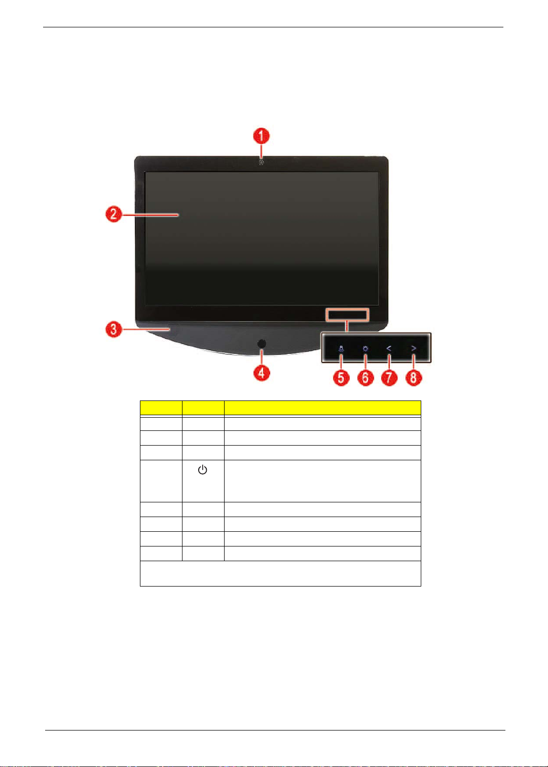
Front View
Item Icon Component
1 Integrated webcam
2 Display screen
3 Speakers
4 Power button/indicator
• Blue – System is in power-on mode
• Flashing blue – System is in standby mode
5 Auxiliary lighting capacitive key
6 LCD brightness capacitive key
7 Decrease volume capacitive key
8 Increase volume capacitive key
NOTE: Icons for the capacitive keys are only visible when the system
is turned on.
Packard Bell oneTwo M3350 / oneTwo M3351 / oneTwo L5350 / oneTwo L5351 Service Guide 3
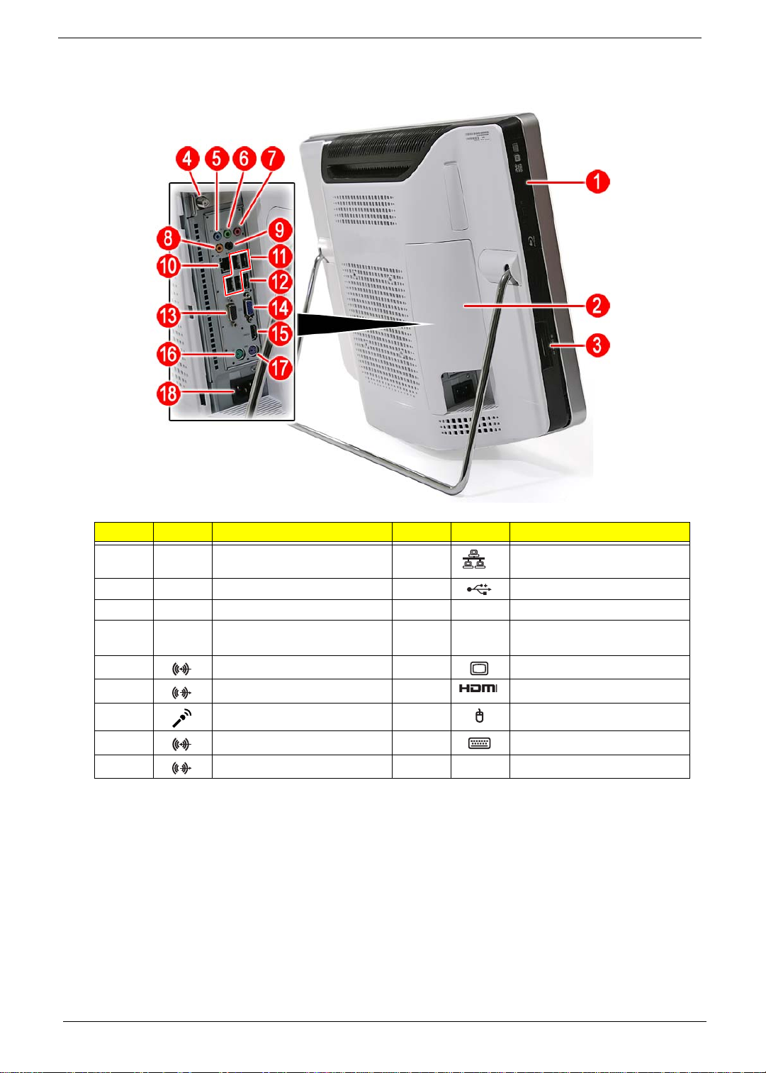
Left View
Item Icon Component Item Icon Component
1 Optical disc drive (ODD) 10 Ethernet port (RJ-45)
2 I/O cable cover 11 USB ports
3 9-in-1 card reader 12 eSATA port
4 HD dual digital TV tuner
(optional)
5 Line-in jack 14 Monitor port
6 Line-out jack 15 HDMI port
7 Microphone jack 16 PS/2 mouse port
8 Line-in jack 17 PS/2 keyboard port
9 Line-out jack 18 AC power jack
13 Serial-to-DVI port (optional)
4 Packard Bell oneTwo M3350 / oneTwo M3351 / oneTwo L5350 / oneTwo L5351 Service Guide
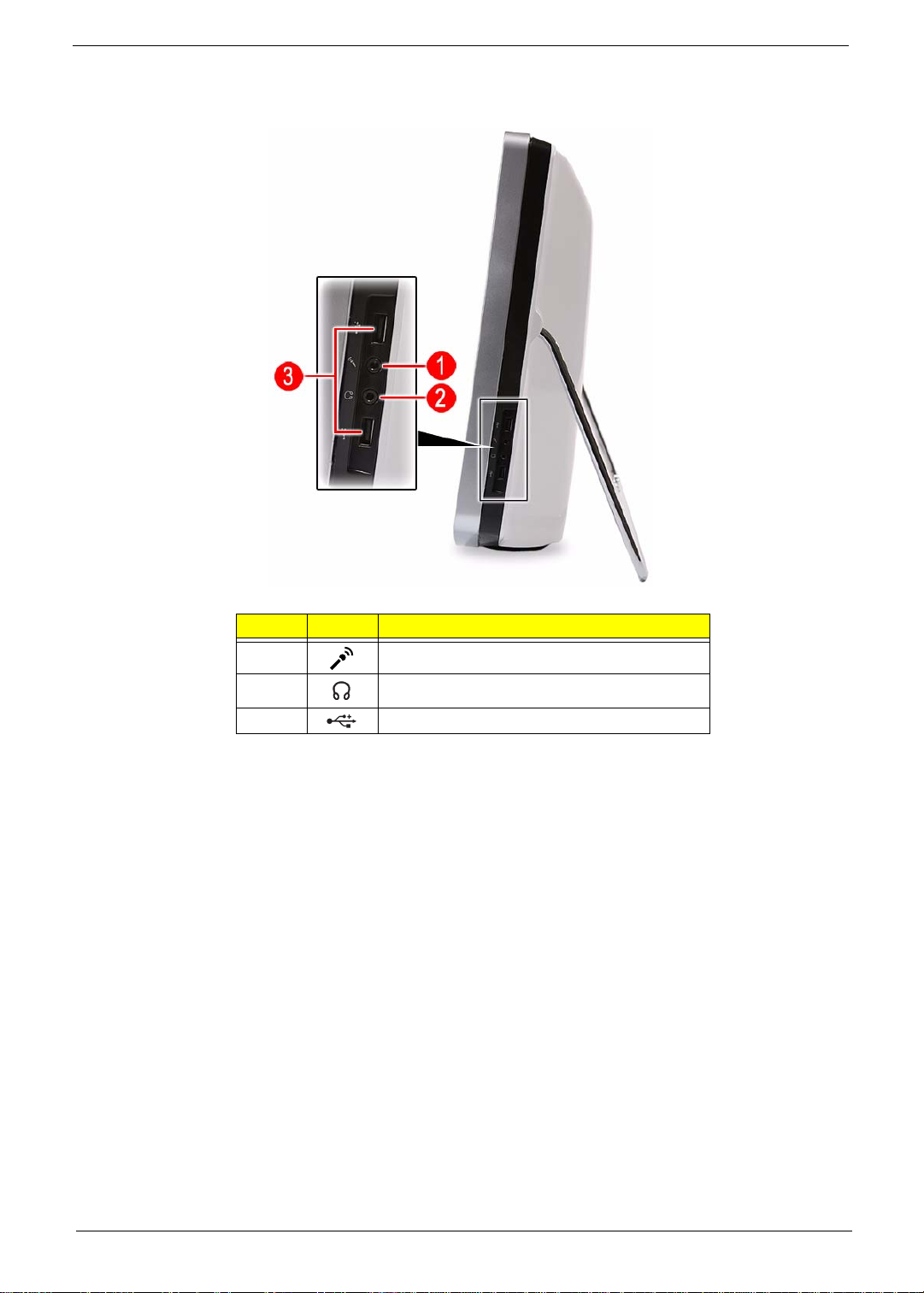
Right View
Item Icon Component
1 Microphone jack
2 Line-out jack
3 USB ports
Packard Bell oneTwo M3350 / oneTwo M3351 / oneTwo L5350 / oneTwo L5351 Service Guide 5
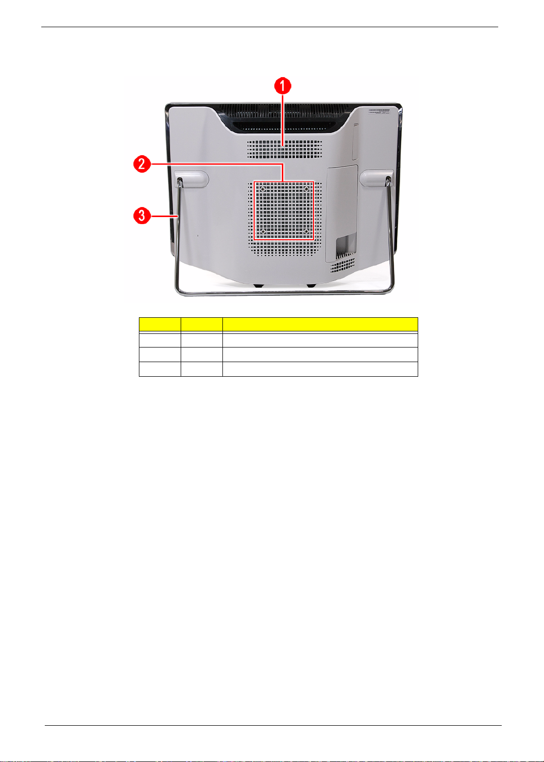
Rear View
Item Icon Component
1 Ventilation slots
2 Mounting holes for wall mount option
3 Computer stand
6 Packard Bell oneTwo M3350 / oneTwo M3351 / oneTwo L5350 / oneTwo L5351 Service Guide
Hardware Specifications
Processor
AMD Phenom II Processors
Item Specification
Series X3 X4
Model 700e 705e 900e 910e
Frequency 2.4 GHz 2.5 GHz 2.4 GHz 2.5 GHz
# of cores 3 3 4 4
L2 cache 1.5 MB 1.5 MB 2 MB 2 MB
L3 cache 6 MB 6 MB 6 MB 6 MB
Package type 45 nm 45 nm 45 nm 45 nm
Socket Socket AM3 Socket AM3 Socket AM3 Socket AM3
Max TDP 65 W 65 W 65 W 65 W
AMD Athlon II Processors
Item Specification
Series X2 X3 X4
Model 215 240 245 405e 600e 605e
Frequency 2.7 GHz 2.8 GHz 2.9 GHz 2.3 GHz 2.2 GHz 2.3 GHz
# of cores 2 2 2 3 4 4
L2 cache 1 MB 2 MB 2 MB 1.5 MB 2 MB 2 MB
Package type 45 nm 45 nm 45 nm 45 nm 45 nm 45 nm
Socket Socket AM3 Socket AM3 Socket AM3 Socket AM3 Socket AM3 Socket AM3
Max TDP 65 W 65 W 65 W 45 W 45 W 45 W
Chipsets
Item Specification
System chipset nVIDIA GeForce 8200 (MCP78PV)
I/O controller SIO ITE 8720
BIOS
Item Specification
BIOS chip AMI BIOS
Setup utility CMOS Setup Utility
Packard Bell oneTwo M3350 / oneTwo M3351 / oneTwo L5350 / oneTwo L5351 Service Guide 7

Memory
Item Specification
Controller Integrated in the AMD processor
Number of DIMM slot 4
Maximum memory 8 GB (using four 2 GB modules)
Data rate 1333 MT/s
Supported capacities 1 or 2 GB
DIMM type 240-pin DDR3 SO-DIMM
Supported brands A-Data, Apacer, Kingston, Transcend, Unifosa, Samsung
Population rule You can install memory modules in any combination as long as they match the above
specifications.
Hard Disk Drive
Item Specification
Controller Integrated in the nVIDIA GeForce 8200 (MCP78PV)
Form factor 3.5-inch 9.5 mm
Interface SATA 2.0
Supported capacities
320 GB • Seagate Pharaoh (7200 rpm)
• HGST HDT721032SLA380 (7200 rpm)
• WD WD1600AAJS-22L7 (7200 rpm)
500 GB • WD WD5000AAKS-22M9A0 (7200 rpm)
640 GB • Seagate ST3640623AS (7200 rpm)
• HGST HDT721064SLA360 (7200 rpm)
• WD WD6400AAKS-22A7B2 (7200 rpm)
1 TB • Seagate ST31000528AS (7200 rpm)
• HGST HDT721010SLA360 (7200 rpm)
• WD WD10EADS-22M4B0 (5400 rpm) / WD1001FALS-22J7B0 (7200 rpm)
1.5 TB • Seagate ST31500341AS (7200 rpm)
• WD WD15EADS-22P8B0 (5400 rpm)
Optical Disc Drive
Item Specification
Controller Integrated in the nVIDIA GeForce 8200 (MCP78PV)
Type DVD-Super Multi double-layer or Blu-ray Disc combo drive option
Form factor Slim type
Tray height (mm)) 12.7 mm
Interface SATA
Supported models
DVD-Super Multi
double-layer drive
Blu-ray Disc
combo drive
8 Packard Bell oneTwo M3350 / oneTwo M3351 / oneTwo L5350 / oneTwo L5351 Service Guide
•HLDS GT31N
• PLDS DS-8A5SH
• Panasonic UJ141AL/UJ240A
• HLDS CT21N

Ethernet
Item Specification
Controller Marvell 88E1116 Intel WG82567V Gigabit NIC
LAN protocol 10/100/1000 Mbps
LAN connector type RJ-45
Wireless LAN
Item Specification
Model Lite-On WN6607LH
Protocol 802.11 b/g/n
Form factor PCIe Mini Card
Bluetooth
Item Specification
Model • Lite-On WB111C-C1
• Xavi BC10B-04C1
Version Bluetooth 2.1 + EDR
Audio
Item Specification
Controller Realtek ALC888S 7.1+2 Channel High Definition Audio Codec
Features • Two built-in 5W stereo speakers
• Right panel audio jacks
– Headphone jack
– Microphone jack
• Left panel audio jacks
– Line-in, line-out, and microphone jacks
– Line-in and line-out jacks
Webcam
Item Specification
Resolution 2.0 MP
Supported models • Chicony CNFA21321004590L
• Park Orchid C04PL037F
• Primax 50-704A4WNT8
Packard Bell oneTwo M3350 / oneTwo M3351 / oneTwo L5350 / oneTwo L5351 Service Guide 9

LCD Panel
Item Specification
Model ZX6350 and ZX6351 ZX4350 and ZX4351
Screen size (diagonal, inch) 21.5-inch 23-inch
Type Wide XGA
Resolution 1920 × 1080
Backlight CCFL
Interface LVDS
Brightness (typical) 300 nits
Display colors 16.7M
Aspect ratio 16:9
Contrast ratio 1000:1
Response time (typical) 5 ms
Touchscreen • ZX6350: Yes
• ZX6351: No
Surface treatment AG type, 3H hard coating, Haze 25
Supported models • • LG LM230WF1
Inverter board • • Darfon VZ.13156.B01
• ZX4350: Yes
• ZX4351: No
• Samsung LTM230HT01
• E-Turbo SR-230M182235D1 (t ouch
panel)
• Sumida IV30260SPEC139
Power Supply Unit
Item Specification
Output (max.) 220 W
Supported models • Lite-On PS-5221-06A1 / PE-5221-08AP / PS-5221-9AE
• Delta DPS-220UB-1 A / DPS-220UB A / DPS-220UB-2 B
• Chicony CPB09-D220R / CPB09-D220A / CPB09-D220E
10 Packard Bell oneTwo M3350 / oneTwo M3351 / oneTwo L5350 / oneTwo L5351 Service Guide

Chapter 2
System Utilities
CMOS Setup Utility
CMOS Setup Utility is a hardware configuration program built into the system ROM. Since most systems are
already properly configured and optimized, there is normally no need to run this utility.
You will need to run this utility under the following conditions:
• When changing the system configuration including:
• Setting the system time and date
• Configuring the system drives and peripherals
• Specifying the boot device sequence
• Configuring the power management modes
• Setting up system passwords or making other changes to the security setup
• When trying to resolve IRQ conflicts
• When a configuration error is detected by the system and you are prompted ("Run Setup" message) to
make changes to the BIOS settings.
The Setup Utility loads the configuration values in a battery-backed nonvolatile memory called CMOS RAM.
This memory area is not part of the system RAM, which allows configuration data to be retained when power is
turned off. The values take effect when the system is booted. POST uses these values to configure the
hardware. If the values and the actual hardware do not agree, POST generates an error message. You must
run this utility to change the hardware settings from the default or current configuration.
IMPORTANT If you repeatedly receive “Run Setup” messages, the RTC battery located on the mainboard
(BT1) may be defective. In this case, the system cannot retain configuration values in CMOS.
Replace the RTC battery with a new one.
NOTE For ease of reading, CMOS Setup Utility will be simply referred to as “Setup” or “Setup Utility” in this
Service Guide.
Packard Bell oneTwo M3350 / oneTwo M3351 / oneTwo L5350 / oneTwo L5351 Service Guide 11
Accessing the Setup Utility
1. Turn on the computer.
If the computer is already turned on, save your data and close all open applications, then restart the
computer.
2. During POST, press Delete.
If you fail to press Delete before POST is completed, you will need to restart the computer.
Use the Up/Down/Left/Right arrow keys to move between the menu options, then press Enter to execute that
option.
Some options lead to pop-up dialog boxes that prompt you to verify that you wish to execute that option. Other
options lead to dialog boxes that prompt you for information.
Some options (marked with a ) lead to submenus that enable you to change the values for the option. Use
the Up/Down/Left/Right arrow keys to scroll through the items in the submenu
12 Packard Bell oneTwo M3350 / oneTwo M3351 / oneTwo L5350 / oneTwo L5351 Service Guide

Navigating through the Setup Utility
Use the keys listed in the legend bar on the bottom of the Setup screen to work your way through the various
menu and submenu screens of the Setup Utility. The table below lists these legend keys and their respective
functions.
Key Function
Up/Down/Left/
Right arrow keys
Enter • To open the page for the currently selected menu/submenu
PgUp and PgDn Move the cursor to the previous and next page of a multipage menu.
Home Move the cursor to the first page of a multipage menu.
End Move the cursor to the last page of a multipage menu.
+ and - To select a value for the currently selected field (only if it is user-configurable). Press these
Esc If you press this key:
F1 To bring up the General Help window. The General Help window describes other Setup
F9 Press to load default system values.
F10 Press to save changes and close the Setup Utility.
Move the cursor to the menu/field you want.The currently selected field will be highlighted.
• To apply a field value.
keys repeatedly to display all possible entries. A parameter that is enclosed in square
brackets [ ] is user-configurable. Grayed-out parameters are not user-configurable for one
of the following reasons:
• The field value is auto-configured or auto-detected.·
• The field value is informational only.
• The field is password-protected.
• On one of the primary menu screens, the Exit menu displays.
• On a submenu screen, the previous screen displays.
• When you are making selections from a pop-up menu, cl oses the pop-u p wit hout mak ing
a selection.
navigation keys that are not displayed on the legend bar.
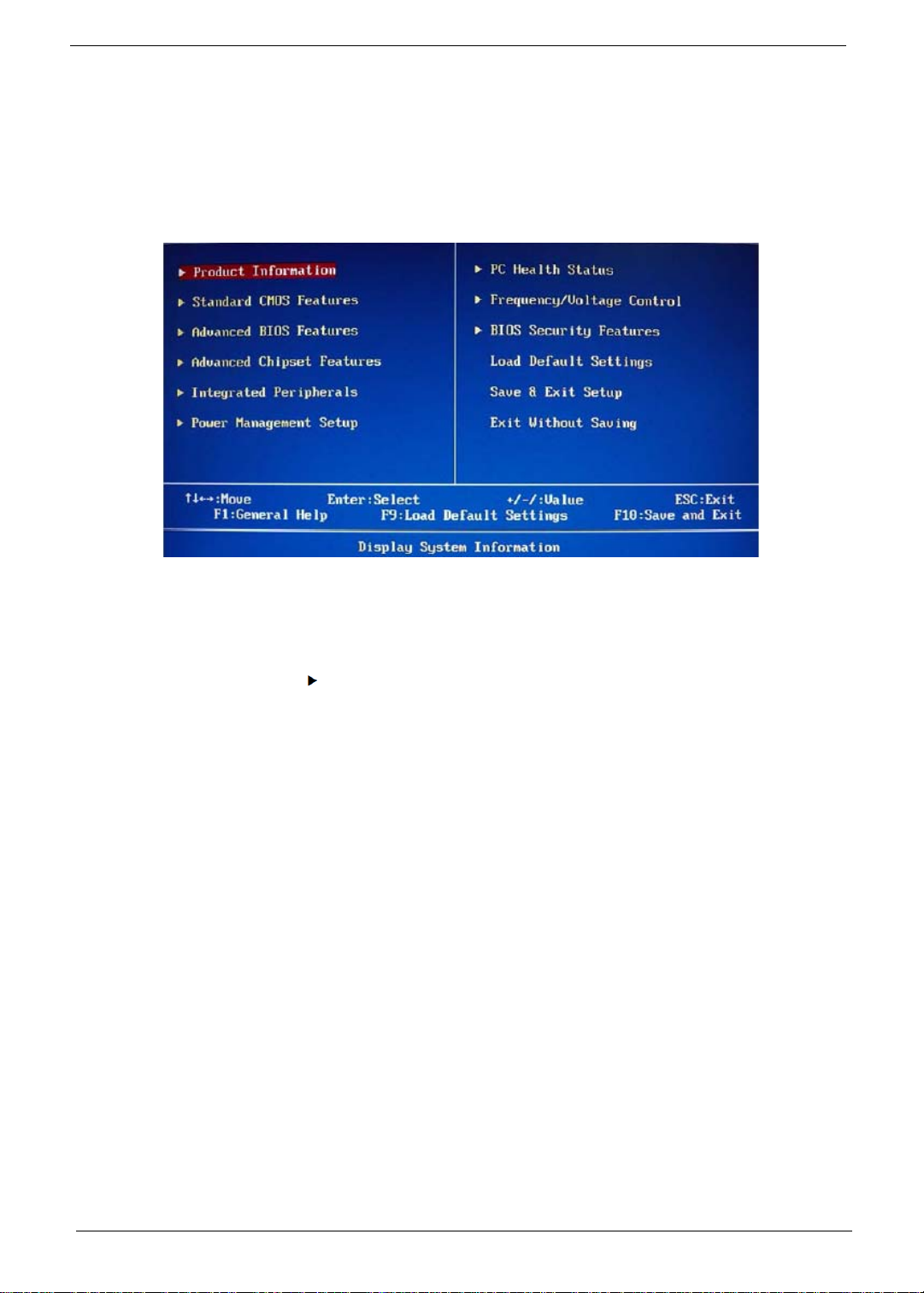
Setup Utility Menus
The Setup Utility has twelve menus for configuring the various system functions. These include:
• Product Information
• Standard CMOS Features
• Advanced BIOS Features
• Advanced Chipset Features
• Integrated Peripherals
• Power Management Setup
NOTES • The screenshots used in this section are for illustration only. The values displayed may not be
the same as those in your computer.
• In the descriptive tables following each of the menu screen illustrations, settings in boldface are
the default and suggested settings.
Packard Bell oneTwo M3350 / oneTwo M3351 / oneTwo L5350 / oneTwo L5351 Service Guide 13
• PC Health Status
• Frequency/Voltage Control
• BIOS Security Features
• Load Default Settings
• Save & Exit Setup
• Exit Without Saving
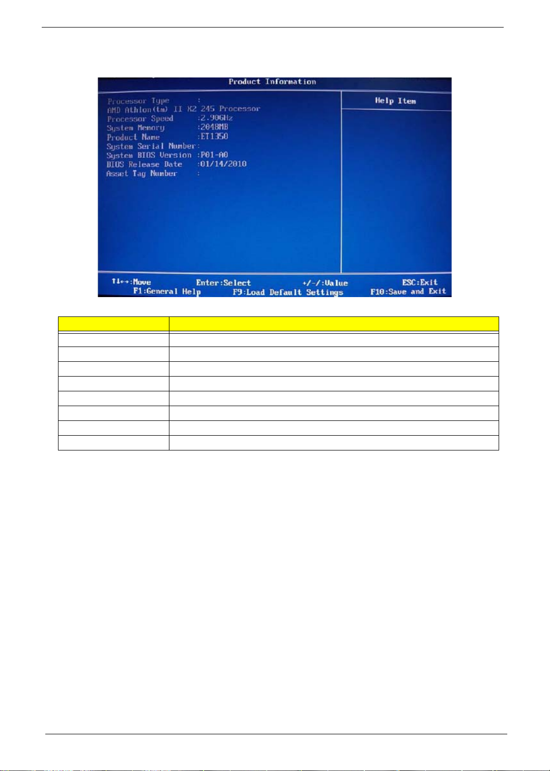
Product Information
.
Field Description
Processor Type Type of processor installed on the system
Processor Speed Speed of the processor installed on the system
System Memory Size of system memory detected during boot-up
Product Name Official model name of the computer.
System Serial Number System serial number.
System BIOS Version Current system BIOS version
BIOS Release Date Date when the CMOS setup utility was released.
Asset Tag Number System asset tag number
14 Packard Bell oneTwo M3350 / oneTwo M3351 / oneTwo L5350 / oneTwo L5351 Service Guide
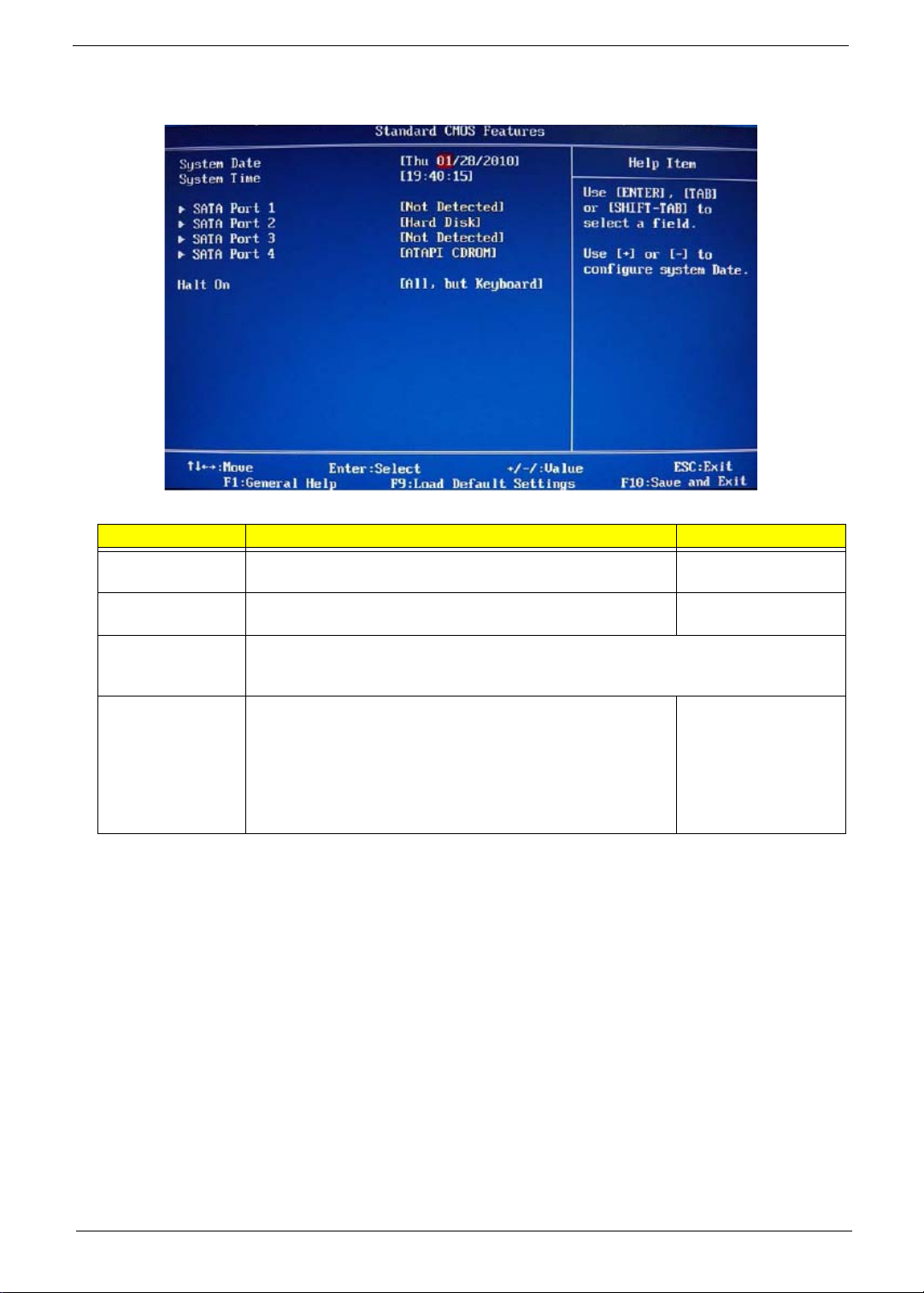
Standard CMOS Features
Field Description Value
System Date Sets the system date. MM/DD/YYYY
(month/day/year)
System Time Sets the system time. HH:MM:SS
(hour:minute:second)
AHCI Port 1–4 Your computer supports four SATA channels, each channel allows one SATA device to be
installed. Press Enter to display the individual configuration screen of installed SATA
drive(s).
Halt On Determines whether the system wil l stop for an error during the
POST. Options include:
• All Errors - Any error detected will pause the system.
• No Errors - BIOS will ignore any errors detected during
POST
• All, but Keyboard - If a keyboard error is detected, BIOS will
pause the system.
All Errors
No Errors
All, But Keyboard
Packard Bell oneTwo M3350 / oneTwo M3351 / oneTwo L5350 / oneTwo L5351 Service Guide 15
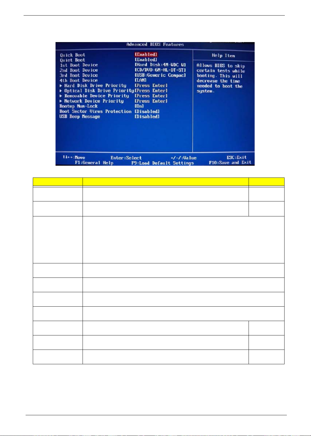
Advanced BIOS Features
Field Description Value
Quick Boot When enabled, the system starts up more qui ckly be eli minati on some of
the POST routines.
Quiet Boot When enabled, BIOS will show a full screen logo when booting; if
disabled, BIOS will show the diagnostic POST screen when booting.
1st/2nd/3rd/4th
Boot Device
Hard Disk Drive
Priority
Optical Disk Drive
Priority
Removable Device
Priority
Network Device
Priority
Bootup Num-Lock If you set this item to On, the keyboard Num Lock key will be active when
Boot Sector Virus
Protection
USB Beep
Message
Displays the device assigned to the specified boot sequence. The Setup Utility attempts
to boot the operating system in this order. By default, the computer searches for boot
devices in the following order:
• Hard disk
• Optical drive (CD/DVD)
• Removable device
• Network boot (LAN)
Press Enter to specify the boot device priority sequence for the installed hard drive(s).
Press Enter to specify the boot device priority sequence for the installed optical drive.
Press Enter to specify the boot device priority sequence for removable drives.
Press Enter to specify the boot device priority sequence foe available network drives.
the computer boots up.
If set to Disabled, when anything attempts to access the boot sector or
hard disk partition table, there will be no warning message.
Select whether to allow the BIOS to emit error beeps or display error
messages during USB device enumeration.
Enabled
Disabled
Enabled
Disabled
On
Off
Enabled
Disabled
Enabled
Disabled
16 Packard Bell oneTwo M3350 / oneTwo M3351 / oneTwo L5350 / oneTwo L5351 Service Guide
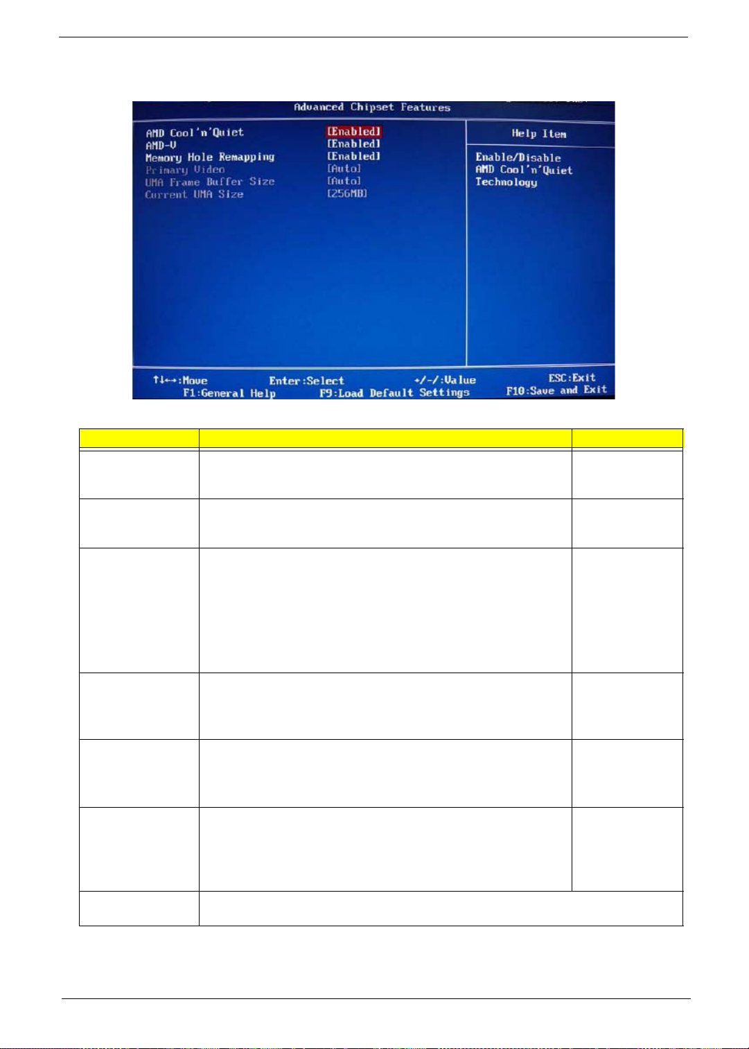
Advanced Chipset Features
Field Description Value
AMD Cool ’n’
Quiet
AMD-V Select whether to enable the AMD-V Technology. This technology
Memory Hole
Remapping
Hybrid SLI Select whether to enable the Hybrid SLI technology when a nVIDIA
Primary Video When a graphics card is installed, you have the option to select
UMA Frame Buffer
Size
Current UMA Size Displays the size of video memory (located in upper memory area–UMA) detected during
Select whether to enable the AMD Cool 'N' Quiet Technology. This
technology allows a compliant OS to dynamically adj ust the system
voltage and core frequency for reduced heat and noise emission.
allows a single platform to run multiple operating systems in
independent partitions.
When enabled, some or all of the memory between the 2 GB and
4
GB limits to addresses above 4 GB. This is a workaround for the
PCI hole or PCI memory hole which is a limit ation of 32-bit hardware
and 32-bit operating systems that causes a computer to appear to
have less memory available than is physically installed.
Note: This feature is useful for systems running on 64-bit OS and
those 32-bit systems that support the Physical Address Extension
method.
graphics card is installed. Hybrid SLI increases graphics
performance with GeForce
management with HybridPower™.
which graphics controller to activate.
Note: When this field is set to Auto, the graphics controller priority
sequence is: PCIE, Onboard, then PCI.
When a graphics card is installed, you can select how the system
video memory (frame buffer) is allotted.
boot-up.
®
Boost and provides intelligent power
Enabled
Disabled
Enabled
Disabled
Enabled
Disabled
Enabled
Disabled
Auto
PCIE
Onboard
PCI
Auto
32 MB
64 MB
128 MB
256 MB
Packard Bell oneTwo M3350 / oneTwo M3351 / oneTwo L5350 / oneTwo L5351 Service Guide 17
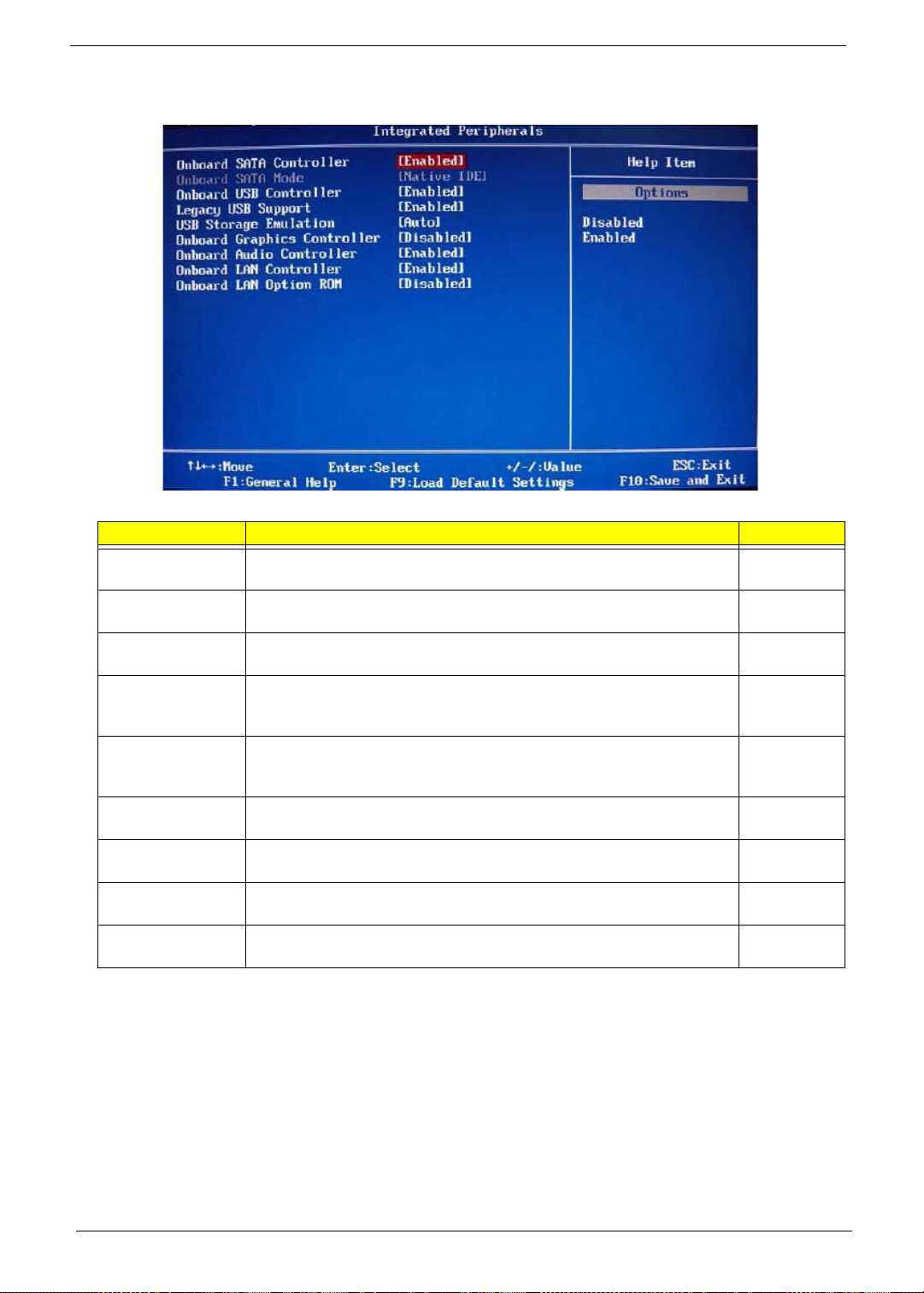
Integrated Peripherals
Field Description Value
Onboard SATA
Controller
Onboard SATA
Mode
Onboard USB
Controller
Legacy USB
Support
USB Storage
Emulation
Onboard Graphics
Controller
Onboard Audio
Controller
Onboard LAN
Controller
Onboard LAN
Option ROM
Enables or disables the onboard SATA controller. Enabled
Set the operating mode for the onboard SATA controller. Native IDE
Enables or disables the onboard USB controller. Enabled
Enables or disables support for a USB mouse and USB keyboard. When
enabled, any attached USB mouse or USB keyboard can control the
system even when there is no USB driver loaded onto the system.
If set to Auto, a USB devices with a capacity of equal or less than 2 GB
will be emulated as a bootable floppy disk.
Enables or disables the onboard graphics controller. Enabled
Enables or disables the onboard audio controller. Enabled
Enables or disables the onboard LAN controller. Enabled
Enables or disables the onboard LAN option ROM function. Enabled
Disabled
Disabled
Enabled
Disabled
Auto
Floppy
Hard Disk
Disabled
Disabled
Disabled
Disabled
18 Packard Bell oneTwo M3350 / oneTwo M3351 / oneTwo L5350 / oneTwo L5351 Service Guide
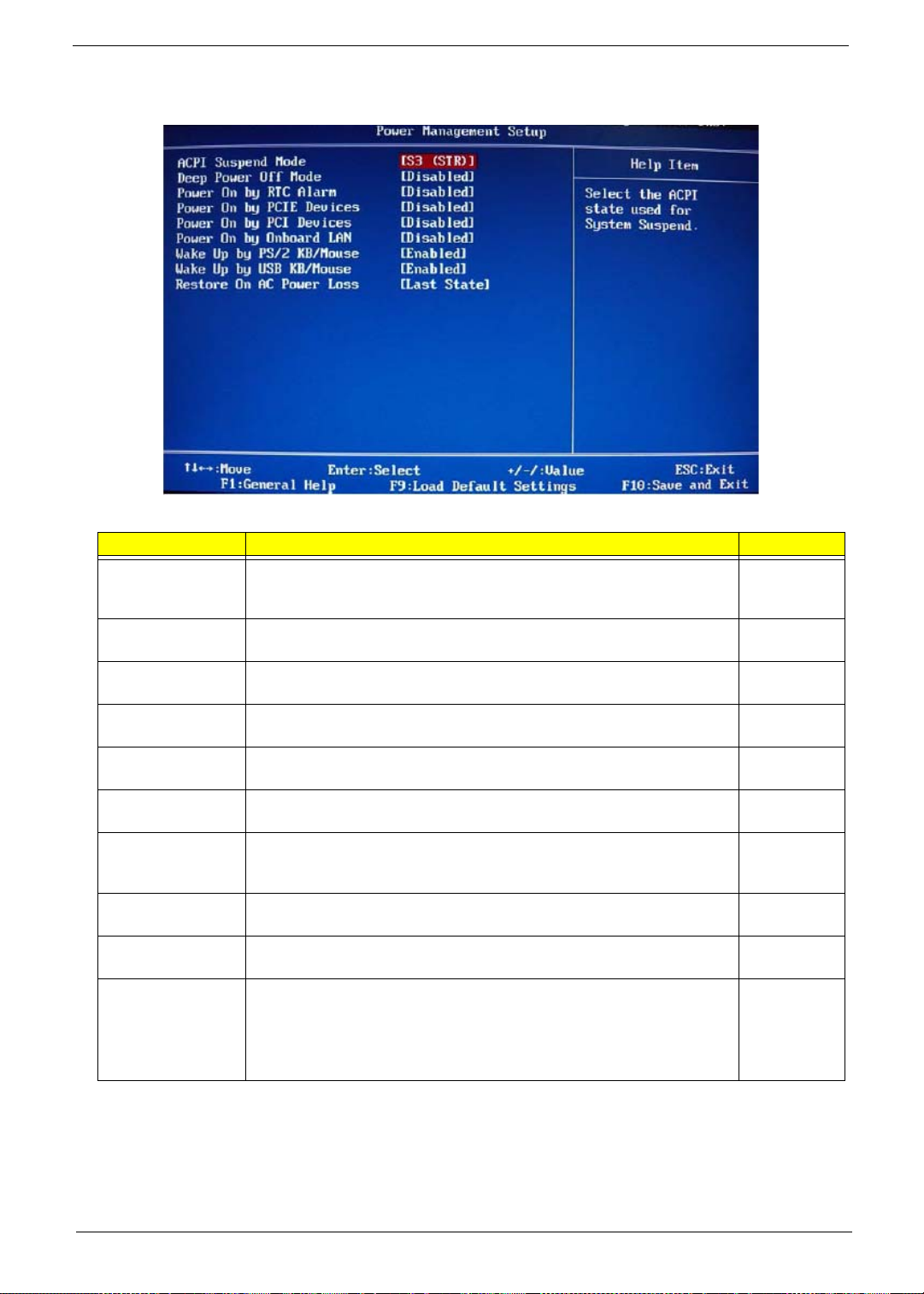
Power Management Setup
Field Description Value
ACPI Suspend
Mode
Deep Power Off
Mode
Power On by RTC
Alarm
Power On by PCIE
Devices
Power On by PCI
Devices
Power On by
Modem Ring
Power On by
Onboard LAN
Use this item to define how your system suspends. Default value is S3
(STR), the suspend mode is suspend to RAM, i.e., the system shuts
down with the exception of a refresh current to the system memory.
Enables or disables compliance to the Energy-using Products Lot 6
Directives (EuP Lot 6).
Enables or disables the system to wake up from a power-saving mode
when an RTC alarm occurs.
Enables or disables the system to wake up from a power-saving mode
when an event occurs on an installed PCI Express device.
Enables or disables the system to wake up from a power-saving mode
when an event occurs on an installed PCI device.
Enables or disables the system to wake up from a power-saving mode
when a modem signal is received. network message
Enables or disables the system to wake up from a power-saving mode
when the onboard LAN controller received a network message.
S3 (STR)
S1 (POS)
Enabled
Disabled
Enabled
Disabled
Enabled
Disabled
Enabled
Disabled
Enabled
Disabled
Enabled
Disabled
Wake Up by PS/2
KB/Mouse
Wake Up by USB
KB/Mouse
Restore On AC
Power Loss
Enables or disables the system to wake up from a power-saving mode
when a PS/2 keyboard or mouse is used.
Enables or disables the system to wake up from a power-saving mode
when a USB keyboard or mouse is used.
Select the power state when an AC power loss occurs.
• Off - The computer remains off until the power button is pressed.
• Last State - The computer reverts to the last power state before the
power loss occurred.
• On - The computer switches back on after the AC power loss.
Enabled
Disabled
Enabled
Disabled
Power Off
Power On
Last State
Packard Bell oneTwo M3350 / oneTwo M3351 / oneTwo L5350 / oneTwo L5351 Service Guide 19
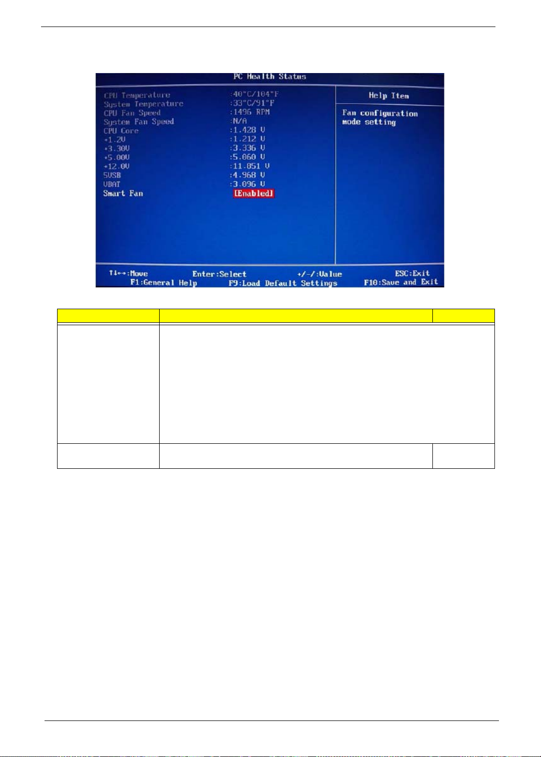
PC Health Status
Field Description Value
CPU Temperature
System Temperature
CPU Fan Speed
System Fan Speed
CPU Core
+1.1V
+3.30V
+5.00V
+12.0V
5VSB
VBAT
Smart Fan When enabled, fan speed will speed up or slow down depending on
These items lets you monitor the parameters for critic al voltages, temperatures and
fan speeds.
the system temperature.
Enabled
Disabled
20 Packard Bell oneTwo M3350 / oneTwo M3351 / oneTwo L5350 / oneTwo L5351 Service Guide
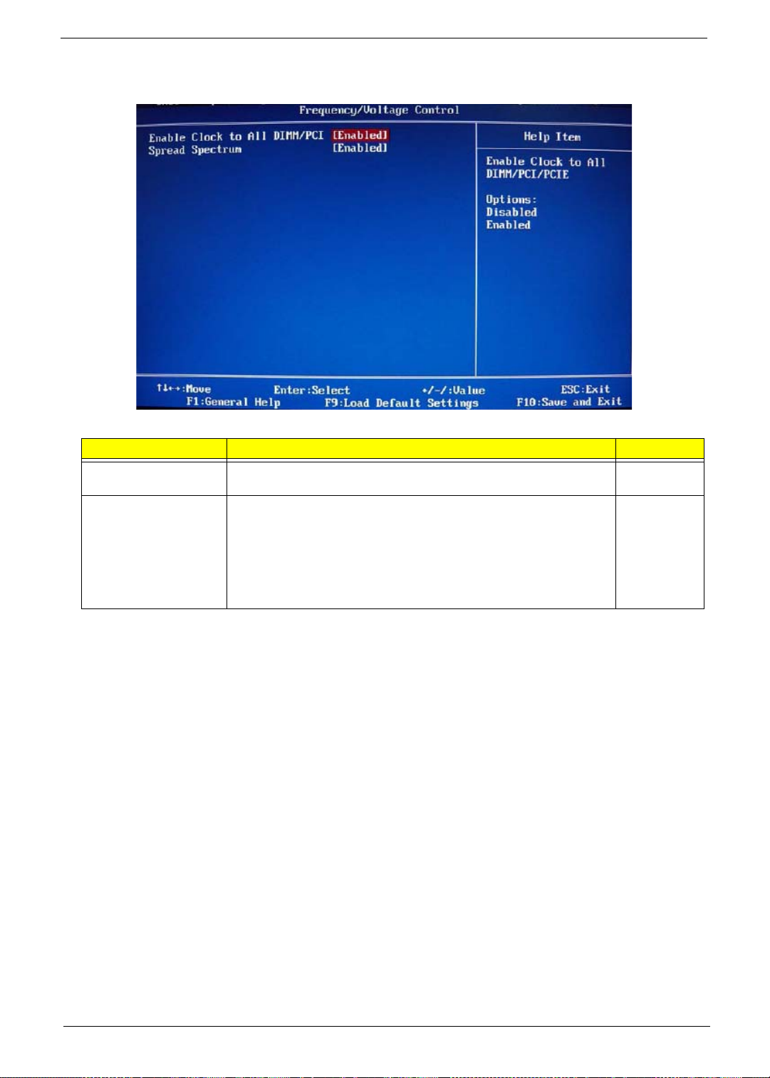
Frequency/Voltage Control
Field Description Value
Enable Clock to All
DIMM/PCI
Spread Spectrum When the mainboard's clock generator pulse s, the extreme va lues of
When enabled, clock signals will be sent to the PCI and memory
slots regardless of whether the slot is occupied or not.
the pulses creates EMI (electromagnetic interference). Set this field
to Enabled to reduce this EMI level. This reduces interference
problems with other electronics in the area.
Note: Remember to disable the Spread Spectrum feature if you are
overclocking. A slight jitter can introduce a temporary boost in clock
speed causing the overclocked processor to lock up.
Enabled
Disabled
Enabled
Disabled
Packard Bell oneTwo M3350 / oneTwo M3351 / oneTwo L5350 / oneTwo L5351 Service Guide 21
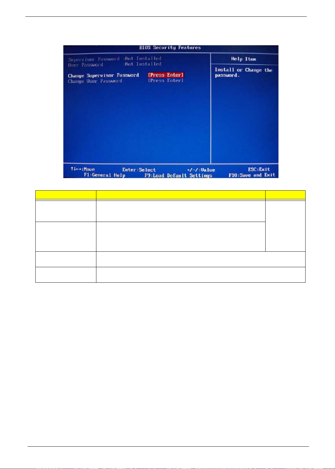
BIOS Security Features
Field Description Value
Supervisor Password Displays the supervisor password status. When set to Installed, this
password will allow the user to access and chan ge all settings in the
Setup Utility.
User Password Displays the user password status. Only the following menus will be
accessible when this password is set as Installed:
• System Date and System Time
• Exit Without Saving
Change Supervisor
Password
Change User
Password
Press Enter to change the supervisor password.
Press Enter to change the user password.
Installed
Not Installed
Note the following before you define a system password:
• The maximum length of password contains 8 alphanumeric characters. The following keys are valid:
– A-Z, a-z (case-insensitive)
– 0-9
– ` - + [ ] \ ; ' , . /,
– Special keypad characters: 0-9 / * - +
• When you are prompted to enter a password, you have three tries before the system halts. Do not forget
your password. If you forget your password, you may have to return your computer to your dealer to reset
it.
22 Packard Bell oneTwo M3350 / oneTwo M3351 / oneTwo L5350 / oneTwo L5351 Service Guide
Loading...