


easynote lj61
Table of contents
 Loading...
Packard Bell EasyNote LJ61
Service Guide
PRINTED IN TAIWAN
Service guide files and updates are available
on the ACER/CSD web; for more information,
please refer to http://csd.acer.com.tw

II
Revision History
Please refer to the table below for the updates made to this service guide.
Date Chapter Updates

III
Copyright
Copyright © 2009 by Acer Incorporated. All rights reserved. No part of this publication may be reproduced,
transmitted, transcribed, stored in a retrieval system, or translated into any language or computer language, in
any form or by any means, electronic, mechanical, magnetic, optical, chemical, manual or otherwise, without
the prior written permission of Acer Incorporated.
Disclaimer
The information in this guide is subject to change without notice.
Acer Incorporated makes no representations or warranties, either expressed or implied, with respect to the
contents hereof and specifically disclaims any warranties of merchantability or fitness for any particular
purpose. Any Acer Incorporated software described in this manual is sold or licensed "as is". Should the
programs prove defective following their purchase, the buyer (and not Acer Incorporated, its distributor, or its
dealer) assumes the entire cost of all necessary servicing, repair, and any incidental or consequential
damages resulting from any defect in the software.
Acer is a registered trademark of Acer Corporation.
Intel is a registered trademark of Intel Corporation.
Pentium and Pentium II/III are trademarks of Intel Corporation.
Other brand and product names are trademarks and/or registered trademarks of their respective holders.

IV
Conventions
The following conventions are used in this manual:
SCREEN MESSAGES Denotes actual messages that appear
on screen.
NOTE Gives bits and pieces of additional
information related to the current
topic.
WARNING Alerts you to any damage that might
result from doing or not doing specific
actions.
CAUTION Gives precautionary measures to
avoid possible hardware or software
problems.
IMPORTANT Reminds you to do specific actions
relevant to the accomplishment of
procedures.

V
Preface
Before using this information and the product it supports, please read the following general information.
1. This Service Guide provides you with all technical information relating to the BASIC CONFIGURATION
decided for Acer's "global" product offering. To better fit local market requirements and enhance product
competitiveness, your regional office MAY have decided to extend the functionality of a machine (e.g.
add-on card, modem, or extra memory capability). These LOCALIZED FEATURES will NOT be covered
in this generic service guide. In such cases, please contact your regional offices or the responsible
personnel/channel to provide you with further technical details.
2. Please note WHEN ORDERING FRU PARTS, that you should check the most up-to-date information
available on your regional web or channel. If, for whatever reason, a part number change is made, it will
not be noted in the printed Service Guide. For ACER-AUTHORIZED SERVICE PROVIDERS, your Acer
office may have a DIFFERENT part number code to those given in the FRU list of this printed Service
Guide. You MUST use the list provided by your regional Acer office to order FRU parts for repair and
service of customer machines.

VI

VII
Table of Contents
System Specifications 1
Features . . . . . . . . . . . . . . . . . . . . . . . . . . . . . . . . . . . . . . . . . . . . . . . . . . . . . . . . . . . .1
System Block Diagram . . . . . . . . . . . . . . . . . . . . . . . . . . . . . . . . . . . . . . . . . . . . . . . . .4
Your Notebook tour . . . . . . . . . . . . . . . . . . . . . . . . . . . . . . . . . . . . . . . . . . . . . . . . . . . .5
Front View . . . . . . . . . . . . . . . . . . . . . . . . . . . . . . . . . . . . . . . . . . . . . . . . . . . . . . .5
Left View . . . . . . . . . . . . . . . . . . . . . . . . . . . . . . . . . . . . . . . . . . . . . . . . . . . . . . . .6
Right View . . . . . . . . . . . . . . . . . . . . . . . . . . . . . . . . . . . . . . . . . . . . . . . . . . . . . . .7
Rear View . . . . . . . . . . . . . . . . . . . . . . . . . . . . . . . . . . . . . . . . . . . . . . . . . . . . . . .7
Bottom View . . . . . . . . . . . . . . . . . . . . . . . . . . . . . . . . . . . . . . . . . . . . . . . . . . . . .8
Keyboard Area (selected models) . . . . . . . . . . . . . . . . . . . . . . . . . . . . . . . . . . . . .9
LCD Panel . . . . . . . . . . . . . . . . . . . . . . . . . . . . . . . . . . . . . . . . . . . . . . . . . . . . . .10
Status Indicators . . . . . . . . . . . . . . . . . . . . . . . . . . . . . . . . . . . . . . . . . . . . . . . . .11
TouchPad Basics . . . . . . . . . . . . . . . . . . . . . . . . . . . . . . . . . . . . . . . . . . . . . . . .12
Using the Keyboard . . . . . . . . . . . . . . . . . . . . . . . . . . . . . . . . . . . . . . . . . . . . . . . . . .13
Key Types . . . . . . . . . . . . . . . . . . . . . . . . . . . . . . . . . . . . . . . . . . . . . . . . . . . . . .13
Windows Keys . . . . . . . . . . . . . . . . . . . . . . . . . . . . . . . . . . . . . . . . . . . . . . . . . .14
System Keys . . . . . . . . . . . . . . . . . . . . . . . . . . . . . . . . . . . . . . . . . . . . . . . . . . . .15
Using the System Utilities . . . . . . . . . . . . . . . . . . . . . . . . . . . . . . . . . . . . . . . . . . . . . .16
Acer GridVista (dual-display compatible) . . . . . . . . . . . . . . . . . . . . . . . . . . . . . .16
Hardware Specifications and Configurations . . . . . . . . . . . . . . . . . . . . . . . . . . . . . . .17
System Utilities 27
BIOS Setup Utility . . . . . . . . . . . . . . . . . . . . . . . . . . . . . . . . . . . . . . . . . . . . . . . . . . . .27
Navigating the BIOS Utility . . . . . . . . . . . . . . . . . . . . . . . . . . . . . . . . . . . . . . . . .27
Information . . . . . . . . . . . . . . . . . . . . . . . . . . . . . . . . . . . . . . . . . . . . . . . . . . . . .28
Main . . . . . . . . . . . . . . . . . . . . . . . . . . . . . . . . . . . . . . . . . . . . . . . . . . . . . . . . . .29
Security . . . . . . . . . . . . . . . . . . . . . . . . . . . . . . . . . . . . . . . . . . . . . . . . . . . . . . . .30
Boot . . . . . . . . . . . . . . . . . . . . . . . . . . . . . . . . . . . . . . . . . . . . . . . . . . . . . . . . . . .33
Exit . . . . . . . . . . . . . . . . . . . . . . . . . . . . . . . . . . . . . . . . . . . . . . . . . . . . . . . . . . .34
BIOS Flash Utilities . . . . . . . . . . . . . . . . . . . . . . . . . . . . . . . . . . . . . . . . . . . . . . . . . . .35
DOS Flash Utility . . . . . . . . . . . . . . . . . . . . . . . . . . . . . . . . . . . . . . . . . . . . . . . . .36
WinFlash Utility . . . . . . . . . . . . . . . . . . . . . . . . . . . . . . . . . . . . . . . . . . . . . . . . . .38
Remove HDD/BIOS Password Utilities . . . . . . . . . . . . . . . . . . . . . . . . . . . . . . . . . . . .39
Machine Disassembly and Replacement 43
Disassembly Requirements . . . . . . . . . . . . . . . . . . . . . . . . . . . . . . . . . . . . . . . . . . . .43
General Information . . . . . . . . . . . . . . . . . . . . . . . . . . . . . . . . . . . . . . . . . . . . . . . . . .44
Pre-disassembly Instructions . . . . . . . . . . . . . . . . . . . . . . . . . . . . . . . . . . . . . . .44
Disassembly Process . . . . . . . . . . . . . . . . . . . . . . . . . . . . . . . . . . . . . . . . . . . . .44
External Module Disassembly Process . . . . . . . . . . . . . . . . . . . . . . . . . . . . . . . . . . .45
External Modules Disassembly Flowchart . . . . . . . . . . . . . . . . . . . . . . . . . . . . .45
Removing the Battery Pack . . . . . . . . . . . . . . . . . . . . . . . . . . . . . . . . . . . . . . . .46
Removing the SD dummy card . . . . . . . . . . . . . . . . . . . . . . . . . . . . . . . . . . . . . .47
Removing the Lower Covers . . . . . . . . . . . . . . . . . . . . . . . . . . . . . . . . . . . . . . . .48
Removing the Optical Drive Module . . . . . . . . . . . . . . . . . . . . . . . . . . . . . . . . . .49
Removing the DIMM Modules . . . . . . . . . . . . . . . . . . . . . . . . . . . . . . . . . . . . . . .51
Removing the WLAN Module . . . . . . . . . . . . . . . . . . . . . . . . . . . . . . . . . . . . . . .52
Removing the Primary HDD Module . . . . . . . . . . . . . . . . . . . . . . . . . . . . . . . . . .54
Removing the Secondary HDD Module . . . . . . . . . . . . . . . . . . . . . . . . . . . . . . .56
Main Unit Disassembly Process . . . . . . . . . . . . . . . . . . . . . . . . . . . . . . . . . . . . . . . . .58
Main Unit Disassembly Flowchart . . . . . . . . . . . . . . . . . . . . . . . . . . . . . . . . . . . .58
Removing the Switch Cover . . . . . . . . . . . . . . . . . . . . . . . . . . . . . . . . . . . . . . . .59
Removing the Media Board . . . . . . . . . . . . . . . . . . . . . . . . . . . . . . . . . . . . . . . .62
Removing the Keyboard . . . . . . . . . . . . . . . . . . . . . . . . . . . . . . . . . . . . . . . . . . .63

VIII
Table of Contents
Removing the LCD Module . . . . . . . . . . . . . . . . . . . . . . . . . . . . . . . . . . . . . . . . .65
Removing the Upper Cover . . . . . . . . . . . . . . . . . . . . . . . . . . . . . . . . . . . . . . . .70
Removing the TouchPad Bracket . . . . . . . . . . . . . . . . . . . . . . . . . . . . . . . . . . . .74
Removing the Media Board FFC . . . . . . . . . . . . . . . . . . . . . . . . . . . . . . . . . . . .75
Removing the LED Board . . . . . . . . . . . . . . . . . . . . . . . . . . . . . . . . . . . . . . . . . .76
Removing the Speaker Module . . . . . . . . . . . . . . . . . . . . . . . . . . . . . . . . . . . . . .77
Removing the RTC Battery . . . . . . . . . . . . . . . . . . . . . . . . . . . . . . . . . . . . . . . . .79
Removing the Modem Board . . . . . . . . . . . . . . . . . . . . . . . . . . . . . . . . . . . . . . .80
Removing the USB Board . . . . . . . . . . . . . . . . . . . . . . . . . . . . . . . . . . . . . . . . . .82
Removing the Mainboard . . . . . . . . . . . . . . . . . . . . . . . . . . . . . . . . . . . . . . . . . .84
Removing the RJ-11 Jack . . . . . . . . . . . . . . . . . . . . . . . . . . . . . . . . . . . . . . . . . .85
Removing the CPU Fan . . . . . . . . . . . . . . . . . . . . . . . . . . . . . . . . . . . . . . . . . . .87
Removing the Thermal Module . . . . . . . . . . . . . . . . . . . . . . . . . . . . . . . . . . . . . .88
Removing the CPU . . . . . . . . . . . . . . . . . . . . . . . . . . . . . . . . . . . . . . . . . . . . . . .89
LCD Module Disassembly Process . . . . . . . . . . . . . . . . . . . . . . . . . . . . . . . . . . . . . .90
LCD Module Disassembly Flowchart . . . . . . . . . . . . . . . . . . . . . . . . . . . . . . . . .90
Removing the LCD Bezel . . . . . . . . . . . . . . . . . . . . . . . . . . . . . . . . . . . . . . . . . .91
Removing the Camera Module . . . . . . . . . . . . . . . . . . . . . . . . . . . . . . . . . . . . . .92
Removing the LCD Panel . . . . . . . . . . . . . . . . . . . . . . . . . . . . . . . . . . . . . . . . . .93
Removing the Power Board . . . . . . . . . . . . . . . . . . . . . . . . . . . . . . . . . . . . . . . .94
Removing the LCD Brackets and FPC Cable . . . . . . . . . . . . . . . . . . . . . . . . . . .95
Removing the Microphone Module . . . . . . . . . . . . . . . . . . . . . . . . . . . . . . . . . . .97
Removing the Antennas . . . . . . . . . . . . . . . . . . . . . . . . . . . . . . . . . . . . . . . . . . .98
LCD Module Reassembly Procedure . . . . . . . . . . . . . . . . . . . . . . . . . . . . . . . . . . . .100
Replacing the Antennas, Power Board, and MIC . . . . . . . . . . . . . . . . . . . . . . .100
Replacing the LCD Panel . . . . . . . . . . . . . . . . . . . . . . . . . . . . . . . . . . . . . . . . .103
Replacing the Camera Module . . . . . . . . . . . . . . . . . . . . . . . . . . . . . . . . . . . . .105
Replacing the LCD Bezel . . . . . . . . . . . . . . . . . . . . . . . . . . . . . . . . . . . . . . . . .106
Main Module Reassembly Procedure . . . . . . . . . . . . . . . . . . . . . . . . . . . . . . . .108
Replacing the CPU . . . . . . . . . . . . . . . . . . . . . . . . . . . . . . . . . . . . . . . . . . . . . .108
Replacing the Thermal Module . . . . . . . . . . . . . . . . . . . . . . . . . . . . . . . . . . . . .108
Replacing the CPU Fan . . . . . . . . . . . . . . . . . . . . . . . . . . . . . . . . . . . . . . . . . .109
Replacing the RJ-11 Jack . . . . . . . . . . . . . . . . . . . . . . . . . . . . . . . . . . . . . . . . .110
Replacing the Mainboard . . . . . . . . . . . . . . . . . . . . . . . . . . . . . . . . . . . . . . . . .111
Replacing the USB Board . . . . . . . . . . . . . . . . . . . . . . . . . . . . . . . . . . . . . . . . .112
Replacing the Modem Board . . . . . . . . . . . . . . . . . . . . . . . . . . . . . . . . . . . . . .113
Replacing the Speaker Module . . . . . . . . . . . . . . . . . . . . . . . . . . . . . . . . . . . . .114
Replacing the LED Board . . . . . . . . . . . . . . . . . . . . . . . . . . . . . . . . . . . . . . . . .115
Replacing the Media Board FFC . . . . . . . . . . . . . . . . . . . . . . . . . . . . . . . . . . . .115
Replacing the TouchPad Bracket . . . . . . . . . . . . . . . . . . . . . . . . . . . . . . . . . . .116
Replacing the Upper Cover . . . . . . . . . . . . . . . . . . . . . . . . . . . . . . . . . . . . . . . .116
Replacing the LCD Module . . . . . . . . . . . . . . . . . . . . . . . . . . . . . . . . . . . . . . . .120
Replacing the Keyboard . . . . . . . . . . . . . . . . . . . . . . . . . . . . . . . . . . . . . . . . . .123
Replacing the Media Board . . . . . . . . . . . . . . . . . . . . . . . . . . . . . . . . . . . . . . . .124
Replacing the Switch Cover . . . . . . . . . . . . . . . . . . . . . . . . . . . . . . . . . . . . . . .125
Replacing the Hard Disk Drive Modules . . . . . . . . . . . . . . . . . . . . . . . . . . . . . .127
Replacing the WLAN Module . . . . . . . . . . . . . . . . . . . . . . . . . . . . . . . . . . . . . .128
Replacing the DIMM Modules . . . . . . . . . . . . . . . . . . . . . . . . . . . . . . . . . . . . . .128
Replacing the ODD Module . . . . . . . . . . . . . . . . . . . . . . . . . . . . . . . . . . . . . . .129
Replacing the Lower Covers . . . . . . . . . . . . . . . . . . . . . . . . . . . . . . . . . . . . . . .129
Replacing the SD Dummy Card . . . . . . . . . . . . . . . . . . . . . . . . . . . . . . . . . . . .131
Replacing the Battery . . . . . . . . . . . . . . . . . . . . . . . . . . . . . . . . . . . . . . . . . . . .131
Troubleshooting 133
Common Problems . . . . . . . . . . . . . . . . . . . . . . . . . . . . . . . . . . . . . . . . . . . . . . . . . .133

IX
Table of Contents
Power On Issue . . . . . . . . . . . . . . . . . . . . . . . . . . . . . . . . . . . . . . . . . . . . . . . .134
No Display Issue . . . . . . . . . . . . . . . . . . . . . . . . . . . . . . . . . . . . . . . . . . . . . . . .135
Random Loss of BIOS Settings . . . . . . . . . . . . . . . . . . . . . . . . . . . . . . . . . . . .136
LCD Failure . . . . . . . . . . . . . . . . . . . . . . . . . . . . . . . . . . . . . . . . . . . . . . . . . . . .137
Built-In Keyboard Failure . . . . . . . . . . . . . . . . . . . . . . . . . . . . . . . . . . . . . . . . .137
TouchPad Failure . . . . . . . . . . . . . . . . . . . . . . . . . . . . . . . . . . . . . . . . . . . . . . .138
Internal Speaker Failure . . . . . . . . . . . . . . . . . . . . . . . . . . . . . . . . . . . . . . . . . .138
Internal Microphone Failure . . . . . . . . . . . . . . . . . . . . . . . . . . . . . . . . . . . . . . .140
HDD Not Operating Correctly . . . . . . . . . . . . . . . . . . . . . . . . . . . . . . . . . . . . . .141
ODD Failure . . . . . . . . . . . . . . . . . . . . . . . . . . . . . . . . . . . . . . . . . . . . . . . . . . .142
USB Failure . . . . . . . . . . . . . . . . . . . . . . . . . . . . . . . . . . . . . . . . . . . . . . . . . . . .145
Modem Function Failure . . . . . . . . . . . . . . . . . . . . . . . . . . . . . . . . . . . . . . . . . .145
Wireless Function Failure . . . . . . . . . . . . . . . . . . . . . . . . . . . . . . . . . . . . . . . . .146
BT Unit Failure . . . . . . . . . . . . . . . . . . . . . . . . . . . . . . . . . . . . . . . . . . . . . . . . .147
Function Board Failure . . . . . . . . . . . . . . . . . . . . . . . . . . . . . . . . . . . . . . . . . . .148
Thermal Unit Failure . . . . . . . . . . . . . . . . . . . . . . . . . . . . . . . . . . . . . . . . . . . . .148
External Mouse Failure . . . . . . . . . . . . . . . . . . . . . . . . . . . . . . . . . . . . . . . . . . .149
Other Failures . . . . . . . . . . . . . . . . . . . . . . . . . . . . . . . . . . . . . . . . . . . . . . . . . .149
Intermittent Problems . . . . . . . . . . . . . . . . . . . . . . . . . . . . . . . . . . . . . . . . . . . . . . . .150
Undetermined Problems . . . . . . . . . . . . . . . . . . . . . . . . . . . . . . . . . . . . . . . . . . . . . .150
Post Codes . . . . . . . . . . . . . . . . . . . . . . . . . . . . . . . . . . . . . . . . . . . . . . . . . . . . . . . .151
Chipset POST Codes . . . . . . . . . . . . . . . . . . . . . . . . . . . . . . . . . . . . . . . . . . . .151
Jumper and Connector Locations 155
Top View . . . . . . . . . . . . . . . . . . . . . . . . . . . . . . . . . . . . . . . . . . . . . . . . . . . . . .155
Bottom View . . . . . . . . . . . . . . . . . . . . . . . . . . . . . . . . . . . . . . . . . . . . . . . . . . .156
Clearing Password Check and BIOS Recovery . . . . . . . . . . . . . . . . . . . . . . . . . . . .157
Clearing Password Check . . . . . . . . . . . . . . . . . . . . . . . . . . . . . . . . . . . . . . . . .157
BIOS Recovery by Crisis Disk . . . . . . . . . . . . . . . . . . . . . . . . . . . . . . . . . . . . .158
FRU (Field Replaceable Unit) List 161
Packard Bell EasyNote LJ61 Exploded Diagrams . . . . . . . . . . . . . . . . . . . . . . . . . .162
Main Assembly . . . . . . . . . . . . . . . . . . . . . . . . . . . . . . . . . . . . . . . . . . . . . . . . .162
Rear Assembly . . . . . . . . . . . . . . . . . . . . . . . . . . . . . . . . . . . . . . . . . . . . . . . . .163
LCD Assembly . . . . . . . . . . . . . . . . . . . . . . . . . . . . . . . . . . . . . . . . . . . . . . . . .164
Base Top Assembly . . . . . . . . . . . . . . . . . . . . . . . . . . . . . . . . . . . . . . . . . . . . .165
Packard Bell EasyNote LJ61 FRU List . . . . . . . . . . . . . . . . . . . . . . . . . . . . . . . . . . .166
Screw List . . . . . . . . . . . . . . . . . . . . . . . . . . . . . . . . . . . . . . . . . . . . . . . . . . . . .174
Model Definition and Configuration 176
Packard Bell EasyNote LJ61 Series . . . . . . . . . . . . . . . . . . . . . . . . . . . . . . . . . . . . .176
Test Compatible Components 181
Microsoft® Windows® Vista Environment Test . . . . . . . . . . . . . . . . . . . . . . . . . . . .182
Online Support Information 187
Index 189

X
Table of Contents

Chapter 1 1
System Specifications
Features
Below is a brief summary of the computer’s many features:
NOTE: Items marked with * denote only selected models.
Operating System
• Genuine Windows® Vista™
Platform
• AMD Athlon X2 QL-64 2.1GHz
• 1MB Cache
• 667MHz Bus Speed
System Memory
• 3072MB DDR2
• On board with two 200-pin +1.8V DDRII SO-DIMM connector, supporting DDR II 667/800 SDRAM
memory interface design, 0MB DDR RAM on board, Two DDR SODIMM slot. Maximum memory:
2GB per slot. 4GB total.
Display
• Screen resolution: 1600x900
• Monitor size 17.3 inch
• Technology and ratio TFT
Graphics
• ATI Mobility Radeon™ HD3200 up to 1407MB Hypermemory
Storage subsystem
• SATA
• 9.5mm, 2.5" HDD Support with 120GB/160GB/200GB/250GB
• Support Ultra DMA100, S.M.A.R.T
• 5400 RPM
• External USB FDD
Optical Drive
• DVDRW R9
Chapter 1

2 Chapter 1
Audio
• Chipset: Realtek ALC272
• Integrated on motherboard or on PCI Slot Integrated
• Sound Stereo
• Dolby sound room
I/O Interface
• 15 pin CRT port
• HDMI port
• MIC In
• 90W DC-in jack for AC Adapter
• Four External USB 2.0 jacks
• RJ-11 jack for Modem
• RJ-45 jack for LAN
• 5 in 1 connector
Dimensions and Weight
• Chassis dimensions: 412mmx280mmx38.6mm
• Weight: 3.4Kg
Communication
• Ethernet: 10/100/ GigaLAN Ethernet
• WIFI: Wireless b/g
Power subsystem
• Full ACPI 1.0B supported
Special keys and controls
• Power Button
• Launch Manager Button
• Backup Date Button
• Enable/Disable Wireless Button
• Enable/Disable Touch Pad Button
• Enable/Disable Mute Button
• Reduce Volume Button
• Increase Volume Button
Environment
• Temperature:
• Operating: 5 °C to 35 °C
• Non-operating: -20 °C to 65 °C

Chapter 1 3
• Humidity (non-condensing):
• Operating: 20% to 80%
• Non-operating: 20% to 80%
NOTE: Items marked with * denote only selected models.
4 Chapter 1
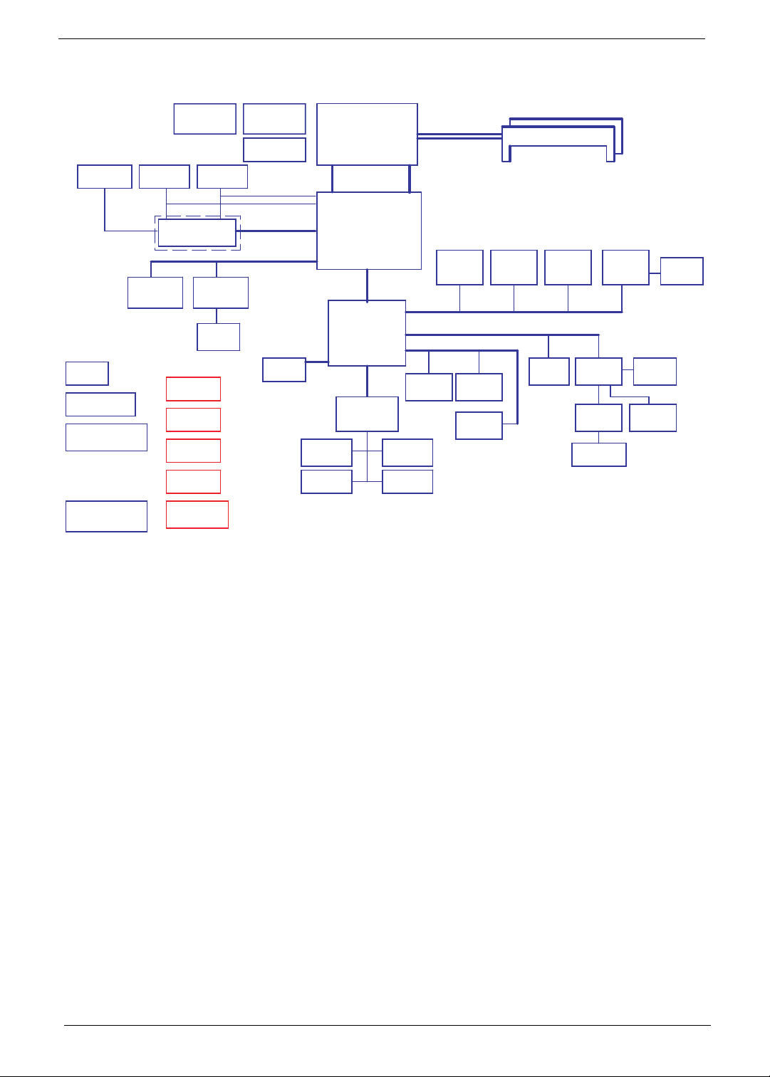
System Block Diagram
Power On/Off CKT.
Touch Pad
CRT Conn.
LPC BUS
BGA-528
MDC 1.5
Conn
Int.KBD
BANK 0, 1, 2, 3
USB Conn
x4
A link
Express2
DC/DC Interface CKT.
AMD S1G2 Processor
3.3V 48MHz
Hyper Transport Link
16 x 16
Clock Generator
ICS9LPRS488B
CIR
Fan Control
Power Circuit DC/DC
uPGA-638 Package
200pin DDRII-SO-DIMM X2
ATI RS780M
EC ROM
1.8V DDRII 667/800
HDA Codec
ALC272
Memory BUS(DDRII)
BGA-528
HD Audio
ATI SB700
Thermal Sensor
ENE KB926
Audio AMP
TPA6017
LCD Conn.
Bluetooth
Conn
3.3V 24MHz
Phone Jack x2
RTC CKT.
Dual Channel
S-ATA
SATA HDD
Conn.
USB/B Conn.
ADM1032
BTN/B Conn.
port 0
USB port 0,1,2,6
CMOS
Camera
USB port 0,1,2,6
USB
LED/B Conn.
SATA ODD
Conn.
HDMI Conn.
PCI-Express 16x
MXM III VGA/B
RJ45
LAN(GbE)
B5784M
MINI Card x2
TV-Tuner WLAN
PCI-Express 1x
port 2
USB port 3 USB port 12 USB port4
port 3port 1,2
5 in 1
Socket
Mono AMP
(for Woofer)
Digital/Analog MIC.
Int. MIC
Media/B Conn.
FUN/B Conn.
BIOS ROM
SPI
Card Reader
RTS5159
port1
Second SATA
HDD Conn.
Chapter 1 5
Your Notebook tour
After knowing your computer features, let us show you around your new computer.
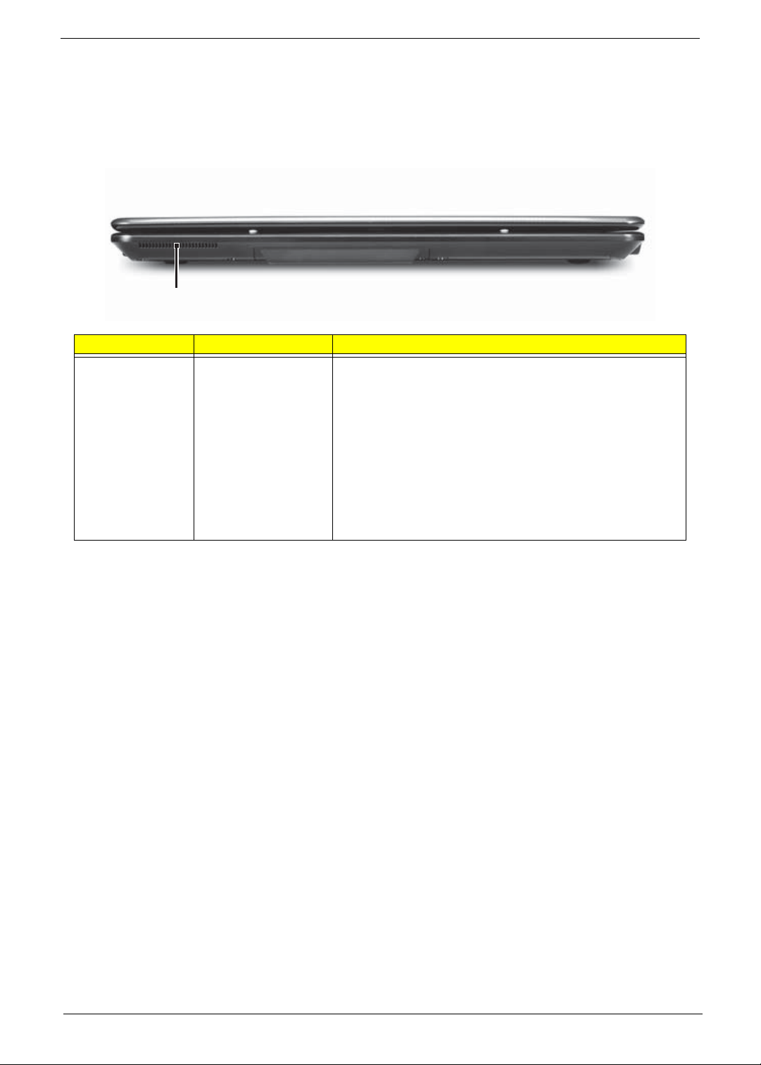
Front View
Component Icon Description
Ventilation fan Helps cool internal components.
Warning: Do not work with the notebook resting on your
lap. If the air vents are blocked, the notebook may become
hot enough to harm your skin.
Caution: Do not block or insert objects into these slots. If
these slots are blocked, your notebook may overheat
resulting in unexpected shutdown or permanent damage to
the notebook.
Caution: Provide adequate space around your notebook
so air vents are not obstructed. Do not use the notebook on
a bed, sofa, rug, or other similar surface.
Ventilation fan
6 Chapter 1
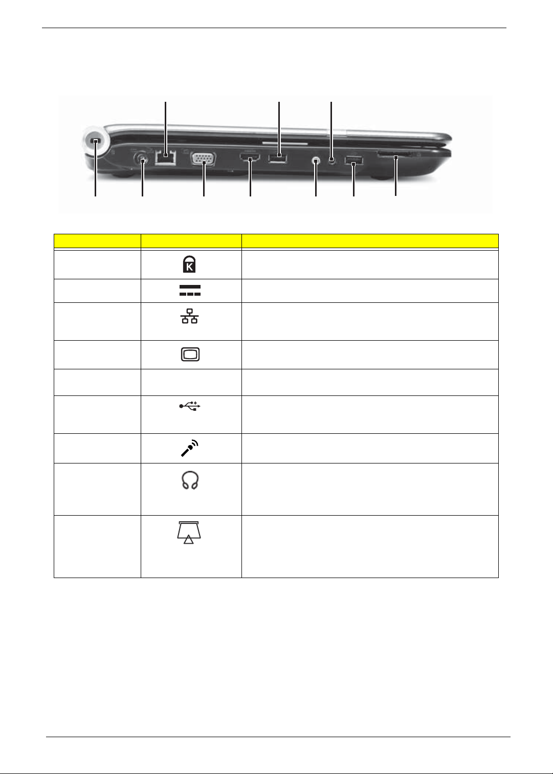
Left View
Component Icon Description
Kensington™
lock slot
Secure your notebook to an object by connecting a
Kensington cable lock to this slot.
Power connector Plug the AC adapter cable into this connector.
Ethernet jack Plug an Ethernet network cable into this jack. Plug the other
end of the cable into a cable modem, DSL modem, or an
Ethernet network jack.
Monitor port Plug an analog VGA monitor or projector into this port.
HDMI out jack HDMI HDMI Plug an HDMI device, such as a high definition
television, into this optional jack.
USB port Plug USB devices (such as a diskette drive, flash drive,
printer, scanner, camera, keyboard, or mouse) into these
ports.
Microphone jack Plug a microphone into this jack.
Headphone jack Plug amplified speakers or headphones into this jack. The
built-in speakers are turned off when speakers or
headphones are plugged into this jack.
• Headphone with SPDIF support
Memory card
reader
Insert a memory card from a digital camera, MP3 player,
PDA, or cellular telephone into the memory card reader.
The memory card reader supports Memory Stick®, Memory
Stick Pro®, MultiMediaCard™, Secure Digital™, and xD-
Picture Card™ cards.
Ethernet
jack
USB
port
Kensington
lock slot
Power
connector
Monitor
port
HDMI out
jack
Microphone
jack
Headphone
jack
Memory card
reader
USB
port
Chapter 1 7
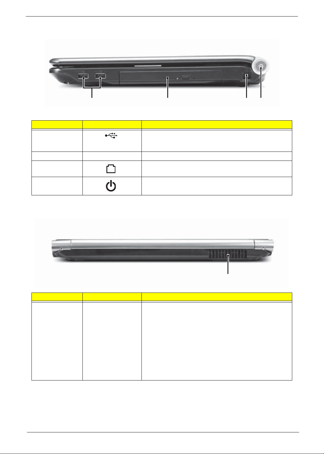
Right View
Rear View
Component Icon Description
USB port Plug a USB device (such as a diskette drive, flash drive,
printer, scanner, camera, keyboard, or mouse) into this
port.
DVD drive Insert CDs or DVDs into this drive.
Modem jack Plug a dial-up modem cable into this optional jack.
Power button Press to turn the power on or off. You can also configure
the power button for Sleep/Resume mode.
Component Icon Description
Ventilation fan Helps cool internal components.
Warning: Do not work with the notebook resting on your
lap. If the air vents are blocked, the notebook may become
hot enough to harm your skin.
Caution: Do not block or insert objects into these slots. If
these slots are blocked, your notebook may overheat
resulting in unexpected shutdown or permanent damage to
the notebook.
Caution: Provide adequate space around your notebook
so air vents are not obstructed. Do not use the notebook on
a bed, sofa, rug, or other similar surface.
DVD drive
USB port
Modem
jack
Power
button
Ventilation fan
8 Chapter 1
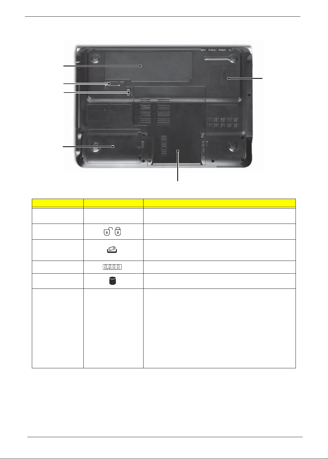
Bottom View
Component Icon Description
Battery Provides power when the notebook is not plugged into AC
power.
Battery lock Slide to unlock the battery.
Battery latch Slide to release the battery.
Memory bay Memory modules are located in this bay.
Hard drive bay The hard drive is located in this bay.
Ventilation slots
and cooling fan
Helps cool internal components.
Warning: Do not work with the notebook resting on your
lap. If the air vents are blocked, the notebook may become
hot enough to harm your skin.
Caution: Do not block or insert objects into these slots. If
these slots are blocked, your notebook may overheat
resulting in unexpected shutdown or permanent damage to
the notebook.
Caution: Provide adequate space around your notebook
so air vents are not obstructed. Do not use the notebook on
a bed, sofa, rug, or other similar surface.
Ventilatio
n
slots and
cooling fa
n
Battery
Battery
latch
Battery
lock
Memory/
Hard drive bay
Hard drive
bay
Chapter 1 9
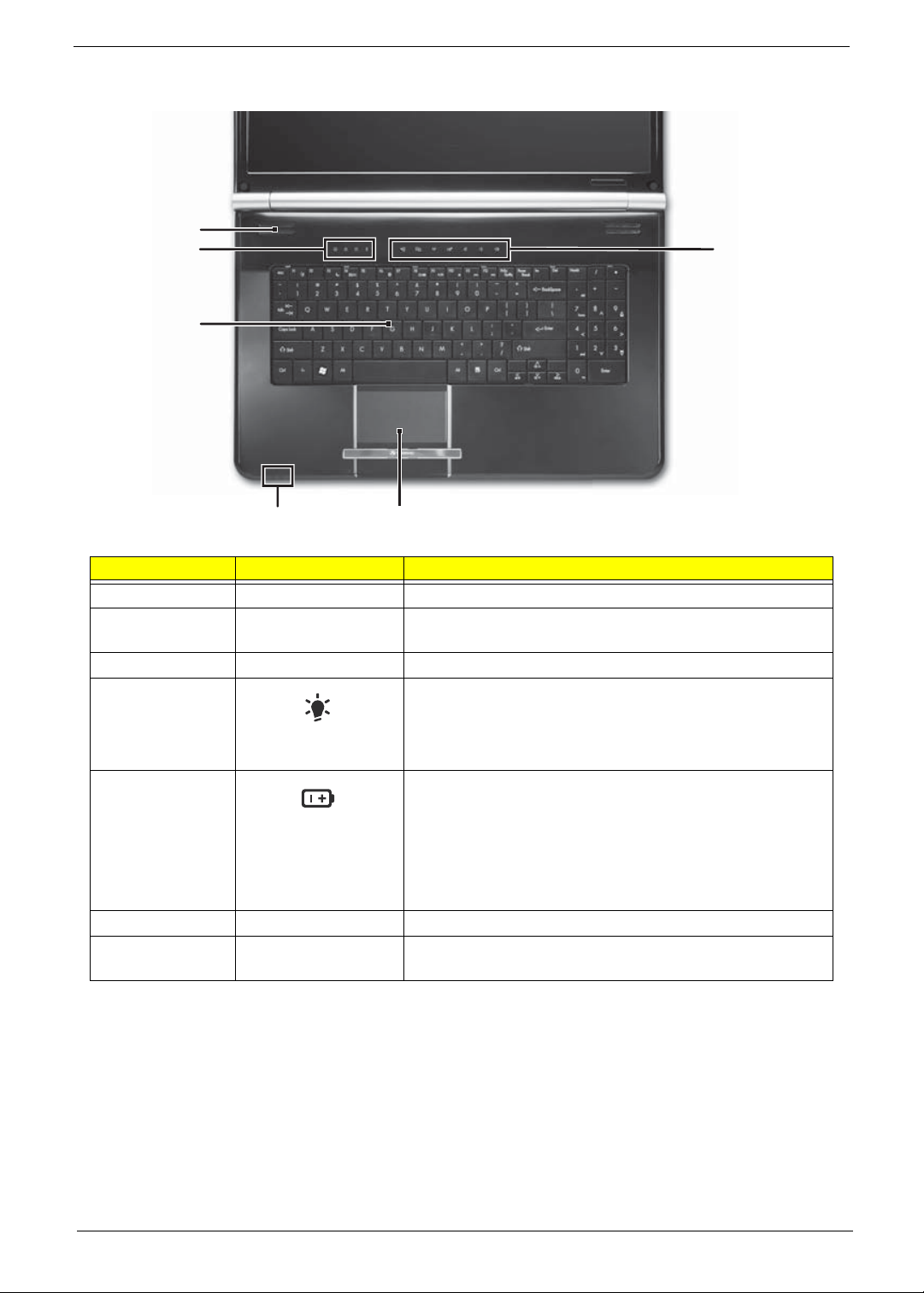
Keyboard Area (selected models)
Component Icon Description
Speakers Left and right speakers deliver stereo audio output.
Status indicators Inform you when a drive is in use or when a button has
been pressed that affects how the keyboard is used.
Keyboard Provides all the features of a full-sized, computer keyboard.
Power indicator • LED on - Notebook is on.
• LED blinking - Notebook is in Sleep or Hybrid Sleep
mode.
• LED off - Notebook is off.
Battery charge
indicator
• LED orange - Battery is fully charged.
• LED blinking orange - Battery is charging.
• LED blinking red - Battery charge is very low.
• LED solid red - Battery is malfunctioning.
Important: This LED only lights up when your notebook is
connected to AC power or the battery charge is very low.
Touchpad Provides all the functionality of a mouse.
Capacitive touch
keys
Press to access capacitive touch key function.
Keyboard
Capacitive
touch keys
Status
indicators
Speakers
Touchpad
Power/Battery
indicators
10 Chapter 1
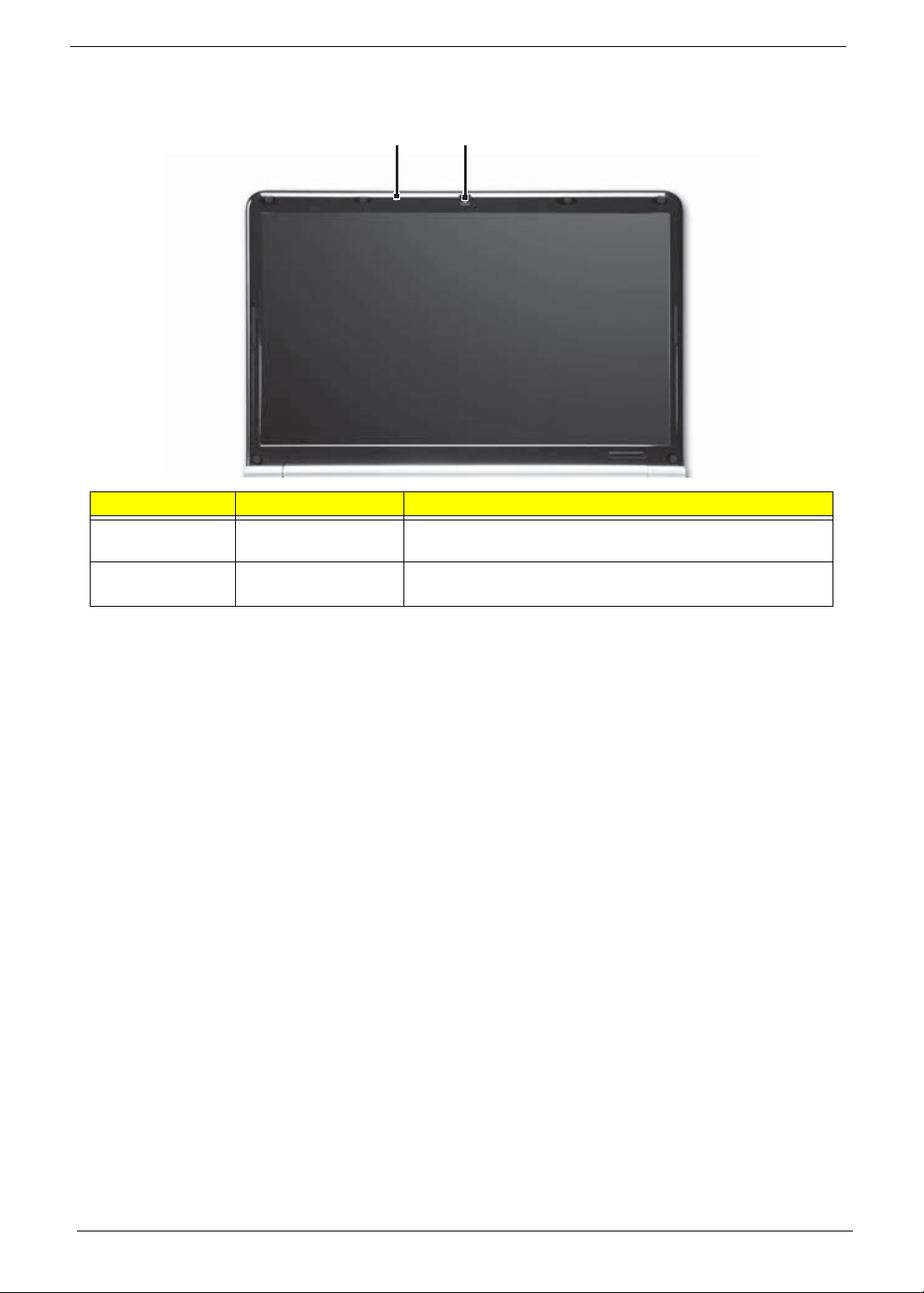
LCD Panel
Component Icon Description
Webcam Use to let others see who they are communicating with
when making VoIP calls.
Microphone Use to talk through when making Voice over Internet
Protocol (VoIP) calls.
Webcam
Microphone

Chapter 1 11
Status Indicators
Status indicators inform you when a drive is being used or when a button has been pressed that affects how
the keyboard is used. The status indicators are located below the screen.
Indicator Icon Description
Bluetooth • LED on - Bluetooth communication is turned on
• LED off - Bluetooth communication is turned off
Hard drive or disk
drive
• LED blinking - The drive is being accessed
• LED off - The drive is not being accessed
Num lock • LED on - Num lock is turned on
• LED off - Num lock is turned off
Caps lock • LED on - Caps lock is turned on
• LED off - Caps lock is turned off
Battery charge
indicator
• LED blue - Battery is fully charged
• LED red - Battery is charging
Important: This LED only lights up when your notebook is
connected to AC power.
Power indicator • LED on - Notebook is on.
• LED blinking - Notebook is in Sleep or Hybrid Sleep mode.
• LED off - Notebook is off.
12 Chapter 1
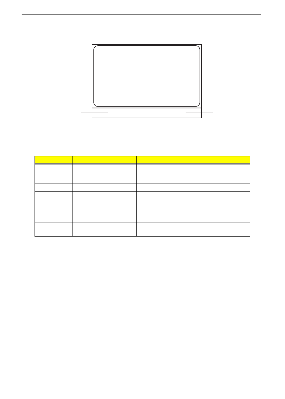
TouchPad Basics
The following items show you how to use the TouchPad:
• Move your finger across the TouchPad (1) to move the cursor.
• Press the left (2) and right (3) buttons located beneath the TouchPad to perform selection and
execution functions. These two buttons are similar to the left and right buttons on a mouse.
Tapping on the TouchPad is the same as clicking the left button.
NOTE: When using the T ouchPad, keep it - and your fingers - dry and clean. The TouchPad is sensitive to
finger movement; hence, the lighter the touch, the better the response. Tapping too hard will not
increase the TouchPad’s responsiveness.
Function Left Button (2) Right Button (3) Main TouchPad (1)
Execute Quickly click twice. Tap twice (at the same speed
as double-clicking a mouse
button).
Select Click once. Tap once.
Drag Click and hold, then use
finger on the TouchPad to
drag the cursor.
Tap twice (at the same speed
as double-clicking a mouse
button); rest your finger on
the TouchPad on the second
tap and drag the cursor.
Access
context menu
Click once.
1
23
Chapter 1 13
Using the Keyboard
Y our notebook features a full-size keyboard that functions the same as a desktop computer keyboard. Many of
the keys have been assigned alternate functions, including shortcut keys for Windows, function keys for
specific system operations, and the Num Lock keys for the numeric keypad.
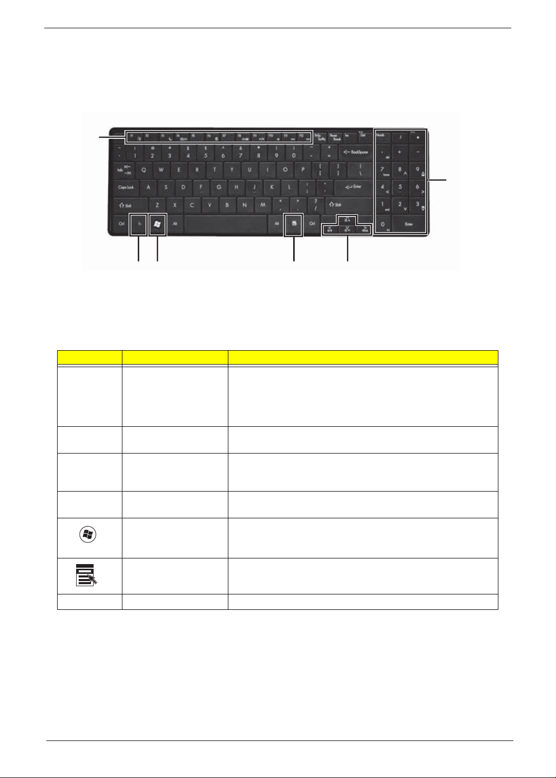
Key Types
The keyboard has several different types of keys. Some keys perform specific actions when pressed alone
and other actions when pressed in combination with another key.
Icon Key Type Description
Function keys Press these keys labeled F1 to F12 to perform actions in
programs. For example, pressing F1 may open help. Each
program uses different function keys for different purposes.
See the program documentation to find out more about the
function key actions.
System keys Press these colored keys in combination with the Fn key to
perform specific actions. See “System Keys” on page 15.
Navigation keys Press these keys to move the cursor to the beginning of a line,
to the end of a line, up the page, down the page, to the
beginning of a document, or to the end of a document.
Fn key Press the Fn key in combination with a colored system key to
perform a specific action.
Windows key Press this key to open the Windows Start menu. This key
can also be used in combination with other keys to open
utilities. See “Windows Keys” on page 14.
Application key Press this key for quick access to shortcut menus and help
assistants in Windows.
Arrow keys Press these keys to move the cursor up, down, right, or left.
Function
keys/
System
keys
F
N
key
Windows key
Application key
Arrow keys
Numeric
keypad/
Navigation
keys
14 Chapter 1
Windows Keys
The keyboard has two keys that perform Windows-specific functions.
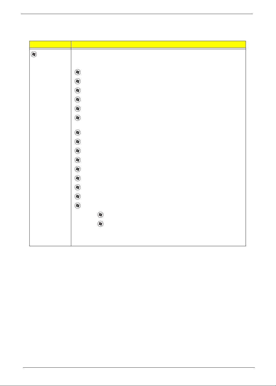
Key Description
Windows key
Pressed alone, this key has the same effect as clicking on the Windows Start button;
it launches the Start menu. It can also be used with other keys to provide a variety of
functions:
<>: Open or close the Start menu
<> + <D>: Display the desktop
<> + <E>: Open Windows Explore
<> + <F>: Search for a file or folder
<> + <G>: Cycle through Sidebar gadgets
<> + <L>: Lock your computer (if you are connected to a network domain), or
switch users (if you're not connected to a network domain)
<> + <M>: Minimizes all windows
<> + <R>: Open the Run dialog box
<> + <T>: Cycle through programs on the taskbar
<> + <U>: Open Ease of Access Center
<> + <X>: Open Windows Mobility Center
<> + <BREAK>: Display the System Properties dialog box
<> + <SHIFT+M>: Restore minimized windows to the desktop
<> + <TAB>: Cycle through programs on the taskbar by using Windows Flip 3-D
<> + <SPACEBAR>: Bring all gadgets to the front and select Windows Sidebar
<CTRL> +
<> + <F>: Search for computers (if you are on a network)
<CTRL> +
<> + <TAB>: Use the arrow keys to cycle through programs on the
taskbar by using Windows Flip 3-D
Note: Depending on your edition of Windows Vista, some shortcuts may not function
as described.

Chapter 1 15
System Keys
The computer employs hotkeys or key combinations to access most of the computer’s controls like screen
brightness, Bluetooth and WiFi.
To activate hot keys, press and hold the <Fn> key before pressing the other key in the hotkey combination.
Function Key Description
Turn the capacitive touch key LEDs on or off.
Enter Sleep mode or Hybrid Sleep mode. Press the power button to leave Sleep
mode.
T oggle the notebook display in the following order: The LCD. An external monitor
or projector (a monitor or projector must be plugged into the monitor port or
HDMI port on your notebook). Both displays at the same time.
Turn the optional Bluetooth radio on or off. Warning: Radio frequency wireless
communication can interfere with equipment on commercial aircraft. Current
aviation regulations require wireless devices to be turned off while traveling in an
airplane. Bluetooth communication devices are examples of devices that provide
wireless communication. Important: The wireless network switch must be in the
ON position for this button to work.
Mute the sound. Press the key combination again to restore the sound.
Turns the display screen backlight off to save power. Press any key to return.
Play/ Pause—Plays or pauses the CD or DVD.
Stop—Stops playing the CD or DVD.
Previous—Skips back one CD track or DVD chapter.
Next—Skips ahead one CD track or DVD chapter.
16 Chapter 1
Using the System Utilities
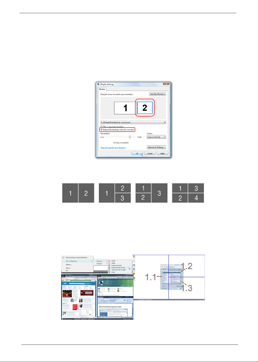
Acer GridVista (dual-display compatible)
NOTE: This feature is only available on certain models.
To enable the dual monitor feature of the notebook, first ensure that the second monitor is connected, then
select Start, Control Panel, Display and click on Settings. Select the secondary monitor (2) icon in the
display box and then click the check box Extend my windows desktop onto this monitor. Finally, click
Apply to confirm the new settings and click OK to complete the process.
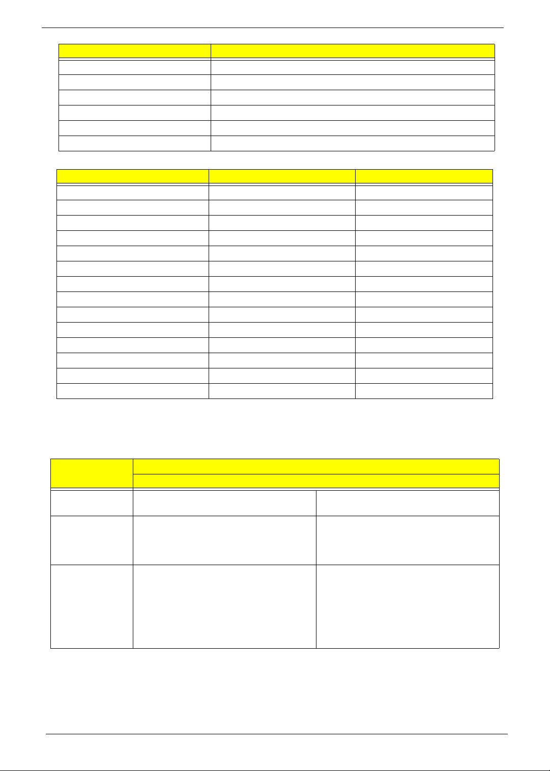
Acer GridVista is a handy utility that offers four pre-defined display settings so you can view multiple windows
on the same screen. To access this function, please go to Start´ All Programs and click on Acer GridVista.
You may choose any one of the four display settings indicated below:
Double (vertical), Triple (primary at left), Triple (primary at right), or Quad Acer Gridvista is dual-display
compatible, allowing two displays to be partitioned independently.
Acer Gridvista is dual-display compatible, allowing two displays to be partitioned independently.
AcerGridVista is simple to set up:
1. Run Acer GridVista and select your preferred screen configuration for each display from the task bar.
2. Drag and drop each window into the appropriate grid.
3. Enjoy the convenience of a well-organized desktop.
NOTE: Please ensure that the resolution setting of the second monitor is set to the manufacturer's
recommended value.

Chapter 1 17
Hardware Specifications and Configurations
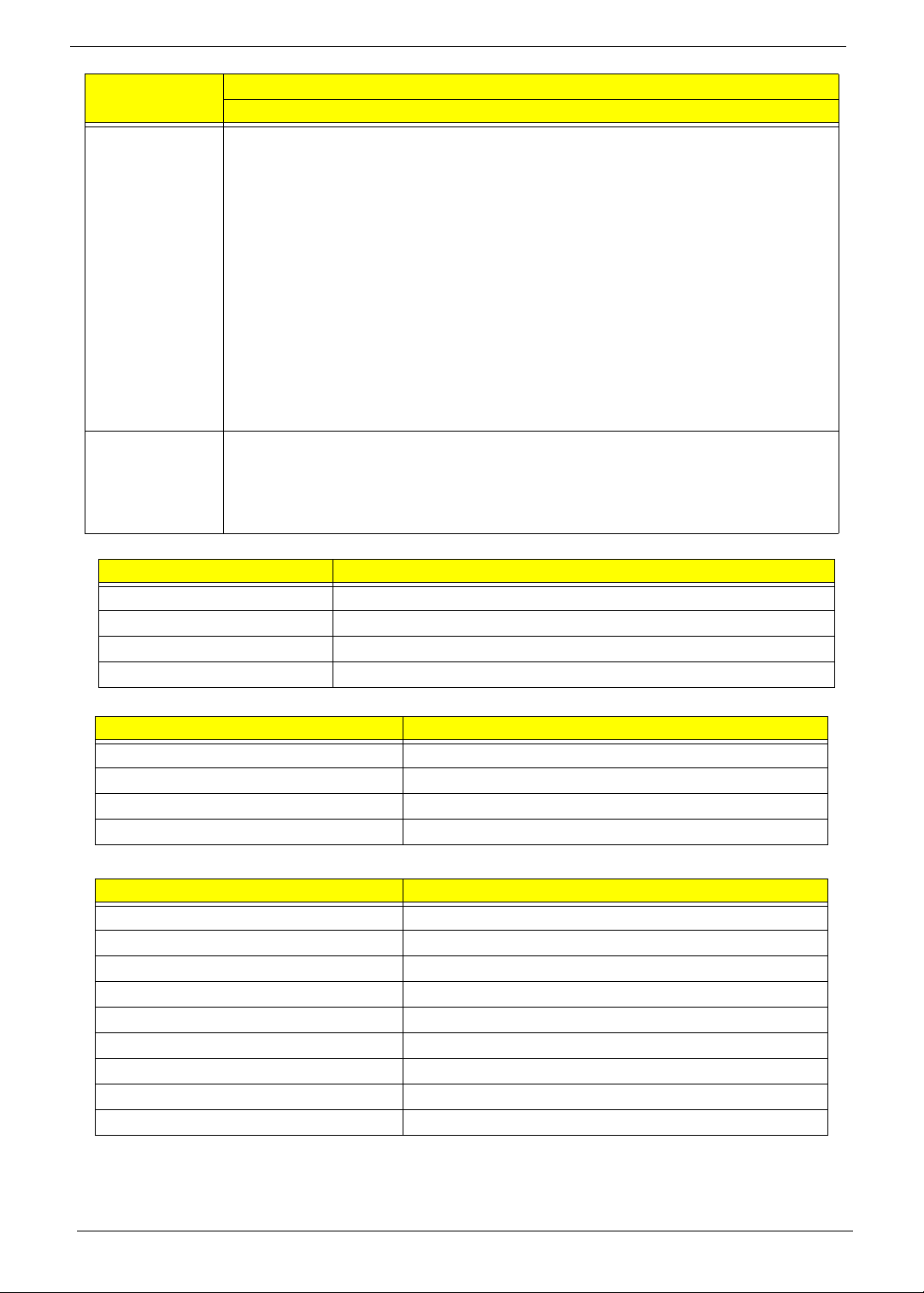
Processor
Processor Specifications
CPU Fan True Value Table
• Throttling 50%: On=100°C, Off=95°C
• OS Shutdown: 105°C
• H/W Shutdown: 86°C
BIOS
System Memory
Item Specification
CPU Mobile AMD Family 11h Processor
Core Logic ·AMD RS780MN
·AMD SB700
CPU Package S1g2 package CPU
Power 35 / 25 W
Item
CPU
Speed
Cores
Mfg.
Tech
cache
Size
Package Power Acer P/N
Athlon64X2 QL60 1.9G 2 65nm 1M PGA 638 35W KC.AQL02.600
Athlon64X2 QL62 2.0G 2 65nm 1M PGA 638 35W KC.AQL02.620
Athlon64X2 QL64 2.1G 2 65nm PGA 638 35W KC.AQL02.640
Athlon QL65 2.1G 1 65nm 1M PGA 638 35W KC.AOL02.650
Turion RM72 2.1G 2 65nm 1M PGA 638 35W KC.TRM02.720
Turion RM74 2.2G 2 65nm 1M PGA 638 35W KC.TRM02.740
Turion RM75 2.2G 1 65nm 1M PGA 638 35W KC.TRM02.750
TurionX2 ZM82 2.2G 2 65nm 2M PGA 638 35W KC.TZM02.820
TurionX2 ZM84 2.3G 2 65nm 2M PGA 638 35W KC.TZM02.840
Turion Ultra ZM85 2.3G 1 65nm 2M PGA 638 35W KC.TZM02.850
TurionX2 ZM86 2.4G 2 65nm 2M PGA 638 35W KC.TZM02.860
Turion Ultra ZM87 2.4G 1 65nm 2M PGA 638 35W KC.TZM02.870
SempronM SI40 2.0G 1 65nm 512K PGA 638 25W KC.SSI02.400
SempronM SI42 2.1G 1 65nm 512K PGA 638 25W KC.SSI02.420
Fan On Temp (°C) Fan Speed (rpm) SPL Spec (dBA)
38 2700 31
42 2900 34
65 3200 37
75 3500 40
Item Specification
BIOS vendor Phoenix
BIOS Version 4.0
Item Specification
Memory controller AMD RS780MN
AMD SB700
Memory size 0MB (onboard)
18 Chapter 1
Memory Combinations
NOTE: Above table lists some system memory configurations. You may combine DIMMs with various
capacities to form other combinations. On above table, the configuration of slot 1 and slot 2 could be
reversed.
Graphics Controller
DIMM socket number 2
Supports memory size per socket 2048MB
Supports maximum memory size 4096MB
Supports DIMM type 200-pin DDRII SO-DIMM
Supports DIMM Speed 667/800 mHz
Supports DIMM voltage +1.8 V
Slot 1 Slot 2 Total Memory
0MB 512MB 512MB
0MB 1024MB 1024MB
0MB 2048MB 2048MB
512MB 512MB 1024MB
512MB 1024MB 1536MB
512MB 2048MB 2560MB
1024MB 0MB 1024MB
1024MB 512MB 1536MB
1024MB 1024MB 2048MB
1024MB 2048MB 3072MB
2048MB 0MB 2048MB
2048MB 512MB 2560MB
2048MB 1024MB 3072MB
2048MB 2048MB 4096MB
Item
Specification
VGA Chip ATI Mobility Radeon™ HD 4570 Intel® GL40/GM45 Express Chipset with
integrated 3D graphics
Graphics Memory 2304 MB of HyperMemory™ (512 MB of
dedicated DDR2 VRAM, up to 1792 MB of
shared system memory)
Up to 1759 MB of Intel® Dynamic Video
Memory Technology 5.0 (128 MB of
dedicated video memory, up to 1631 MB of
shared system memory)
Supports • Unified Video Decoder (UVD)
• OpenEXR High Dynamic-Range (HDR)
technology
• Shader Model 4.1
• Microsoft® DirectX® 10.1Mobile
• Dual independent display support
• Intel® Graphics Media Accelerator
4500M/4500MHD (Intel® GMA 4500M/
4500MHD)
• Microsoft® DirectX® 10
• Dual independent display support
Item Specification

Chapter 1 19
Resolution External resolution/refresh rate:·
2048 x 1536: 75/60 Hz
1920 x 1440: 85/75/60 Hz
1920 x 1200: 75/60 Hz
1920 x 1080: 100/85/75/60 Hz
1680 x 945: 100/85/75/60 Hz
1600 x 1200: 120/100/85/75/60 Hz
1600 x 900: 120/100/85/75/60 Hz
1400 x 1050: 85/75/60 Hz
1366 x 768: 85/75/60 Hz
1280 x 1024: 120/100/85/75/60 Hz
1280 x 960: 85/75/60 Hz
1280 x 768: 85/75/60 Hz
1280 x 720: 100/85/75/60 Hz
1024 x 768: 120/100/85/75/60 Hz
800 x 600: 120/100/85/72/60 Hz
Supports • 16.7 million colors
• MPEG-2/DVD decoding
• WMV9 (VC-1) and H.264 (AVC) decoding
• HDMI™ (High-Definition Multimedia Interface) with HDCP (High-bandwidth Digital
Content Protection) support
Item
Specification
VGA Chip ATI Mobility Radeon™ HD 4570 NVIDIA® GeForce® GT 130M Mobile Intel® GM457 Express
Chipset with integrated 3D
graphics
Graphics Memory 2304 MB of HyperMemory™
(512 MB of dedicated DDR2
VRAM, up to 1792 MB of
shared system memory)
Up to 2815 MB of
TurboCache™ (1024 MB of
dedicated DDR2 VRAM, up to
1791 MB of shared system
memory)
Up to 1759 MB of Intel®
Dynamic Video Memory
Technology 5.0 (128 MB of
dedicated video memory, up to
1631 MB of shared system
memory)
Supports • Unified Video Decoder
(UVD)
• OpenEXR High Dynamic-
Range (HDR) technology
• Shader Model 4.1
• Microsoft® DirectX®
10.1Mobile
• Dual independent display
support
• NVIDIA® CUDA™
• PureVideo® HD technology
• OpenEXR High Dynamic-
Range (HDR) technology
• Shader Model 4.0
• Microsoft® DirectX® 10
• Intel® Graphics Media
Accelerator 4500MHD
(Intel® GMA 4500MHD)
• Microsoft® DirectX® 10
Item
Specification
20 Chapter 1
LAN Interface
Wireless Module 802.11b/g
Bluetooth
Resolution External resolution/refresh rate:·
2048 x 1536: 75/60 Hz
1920 x 1440: 85/75/60 Hz
1920 x 1200: 75/60 Hz
1920 x 1080: 100/85/75/60 Hz
1680 x 945: 100/85/75/60 Hz
1600 x 1200: 120/100/85/75/60 Hz
1600 x 900: 120/100/85/75/60 Hz
1400 x 1050: 85/75/60 Hz
1366 x 768: 85/75/60 Hz
1280 x 1024: 120/100/85/75/60 Hz
1280 x 960: 85/75/60 Hz
1280 x 768: 85/75/60 Hz
1280 x 720: 100/85/75/60 Hz
1024 x 768: 120/100/85/75/60 Hz
800 x 600: 120/100/85/72/60 Hz
Supports • 16.7 million colors
• MPEG-2/DVD decoding
• WMV9 (VC-1) and H.264 (AVC) decoding
• HDMI™ (High-Definition Multimedia Interface) with HDCP (High-bandwidth Digital Content
Protection) support
Item Specification
LAN Chipset Broadcom BCM5784 for 10/1 00/1000LAN
LAN connector type RJ45
LAN connector location Left side
Features Support for 10/100/1000
Item Specification
Manufacturer
Model
Modem Device •
Interface
Item Specification
Model
Operating Frequency
Channel Numbers
Transmitter Output Power
Coverage
Receiver Sensitivity
Maximum Receiver Signal
Operating Voltage
Interface
Item
Specification
Loading...