


OMNIREL OM4202SC, OM4202RC, OM4202DC Datasheet
OM4202SC/RC/DC
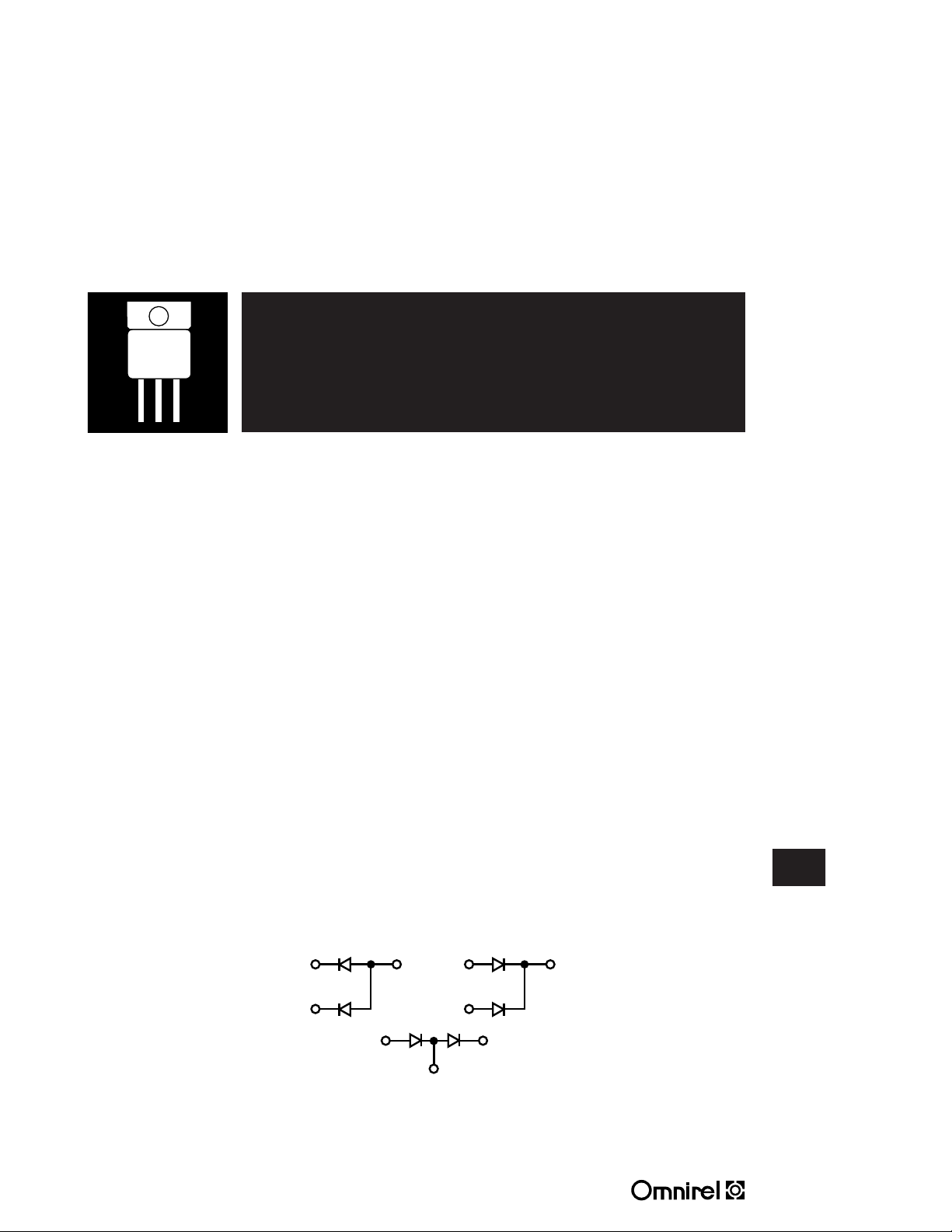
COMMON
ANODE
COMMON
CATHODE
DOUBLER
1
3
2
1
3
2
1
2
3
HERMETIC TO-258AA DUAL POWER SCHOTTKY
RECTIFIER
30 Amp, 45 Volt Rating Center-Tap Rectifier
FEATURES
• Very Low Forward Voltage
• Low Recovery Charge
• Rugged Package Design, (JEDEC TO-258AA)
• High Efficiency For Low Voltage Supplies
• 45V Blocking @ Rated T
• 50V Repetitive Surge Voltage
• Dual Schottky Rectifier In A Single Isolated Package
• Available Non-Isolated (OM4202NC); Common Cathode Only
• Available Screened To MIL-S-19500, TX, TXV And S Levels
jmax
DESCRIPTION
The OM4202SC has two Schottky diodes arranged in a common cathode
configuration and is ideally suited for a full wave output rectifier in low voltage
switching power supplies where small size and high reliablity are required. Common
anode and doubler configurations also available.
ABSOLUTE MAXIMUM RATINGS (T
Peak Inverse Voltage....................................................45 V
Maximum Average D.C. Output Current....................................15 A
Peak Surge Current (Non-Repetitive, 8.3mS)..............................150 A
Peak Reverse Transient Current .........................................1.0 A
Storage Temperature Range ................................- 55° C to + 175° C
Junction OperatingTemperature Range .......................- 55° C to + 150° C
Package Thermal Resistance, Junction-to-Case ........................2.0° C/W
4 11 R4
Supersedes 1 07 R3
= 25°C) Per Diode
C
SCHEMATIC
OMXXXXRC
Common cathode is standard. Contact the factory for performance
characteristics for common anode and doubler.
OMXXXXDC
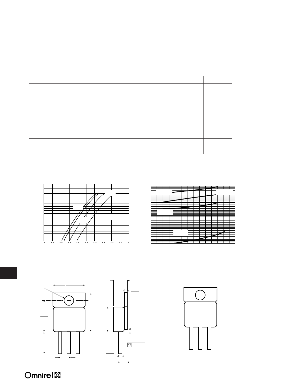
Z-Tab package also available.
3.2 - 17
3.2
OMXXXXSC
205 Crawford Street, Leominster, MA 01453 USA (508) 534-5776 FAX (508) 537-4246
OM4202SC/RC/DC
.707
.697
.750
.500
.835
.815
.695
.685
.165
.155
.200 TYP.
.550
.530
.270
.240
.045
.035
.140 TYP.
.092 MAX.
.065
.055
.005
50
20
10
5
3
1
0.5
0 0.1 0.2 0.3 0.5 0.5 0.6 0.7 0.8 0.9 1
10
1
0.1
0.01
20 40 60 80 100 120
ELECTRICAL CHARACTERISTICS (T
= 25° C) (Per Diode)
C
Characteristic Symbol Max. Unit
Maximum Instantaneous Forward Voltage (1) V
F
IF= 10A, TC= 25°C 0.57
IF= 15A, TC= 25°C 0.64
IF= 15A, TC= 125°C 0.58
Maximum Instantaneous Reverse Current (1) I
TC= 25°C, VR= V
RWM
R
TC= 125°C 50
Capacitance
C
VR= 5.0 V
(1) Pulse Test: Pulse Width = 300µs, Duty Cycle 2.0%.
t
TYPICAL FORWARD VOLTAGE TYPICAL REVERSE CURRENT
TJ= 150°C
TJ= 100°C
150°C
175°C
100°C
TJ= 25°C
Volts
mA
1.0
800 pf
TJ= 125°C
CURRENT (AMPS)
- INSTANTANEIOUS FORWARD
F
I
0 0.1 0.2 0.3 0.4 0.5 0.6 0.7 0.8
VF- INSTANTANEOUS VOLTAGE (VOLTS)
MECHANICAL OUTLINE
3.2
- REVERSE CURRENT (mA)
R
I
TJ= 25°C
VR-REVERSE VOLTAGE (VOLTS)
PIN CONNECTION
123
 Loading...