


OMC510
Rev 03 09/27/00
205 Crawford Street • Leominster MA 01453 • Phone: 978 534 5776 • Fax: 978 537 4246 • www.omnirel.com
1
FEATURES / BENEFITS
• Embedded Motor Control DSP (ADMCF328) improves higher level system integration and flexibility
• 7A phase current (cycle-by-cycle current limit)
• Hall Effect sensor based; sensorless control optional for improved reliability
• Logic supplies (+15V/+5V) generated onboard, eliminating external parts
• Serial port for isolated RS-232 interface allows system level control
• Direction and velocity control
• 2.5 Inch diameter to fit inside motor housing
APPLICATIONS
• Fans
• Pumps
• Compressors
DESCRIPTION
The OMC510 is a DSP-based three-phase brushless DC motor controller intended to replace the analog
controller to improve system integration, efficiency, flexibility, and reliability while reducing the overall
system cost. The standard OMC510 is configured for commutation via Hall effect sensor feedback. In this
configuration, the Hall effect sensor outputs provide discrete absolute rotor position for commutation. The
Hall effect sensor outputs are fed into the control port, level shifted onboard from 15V to 5V, then fed
directly into the DSP. Based on this information, velocity is determined. Alternatively, the OMC510 can be
configured for commutation via sensorless control. Three resistor divider networks are provided onboard for
back EMF measurements. In this configuration, the inactive winding is used to measure the back EMF, and
based on these measurements, estimates of position and velocity are derived. Consult the factory for details.
The OMC510 requires a single ended 28V supply for operation. The logic voltage supplies (15V and 5V) are
derived onboard. The OMC510 will accommodate either an analog or digital command input. For the latter,
a serial port is provided onboard to interface with an isolated RS-232 communications port. The OMC510
provides direction control as well as current limit for over-current protection.
The OMC510 is a 2.5 inch diameter circuit board assembly designed for small size and low cost, and it is
ideal for installation inside a motor housing. The assembly process includes chip-on-board technology for the
driver and power stages to maximize the power density and surface mount technology for the control stage.
The small size, low cost and performance of the OMC510 make it an ideal control solution for applications
including fans, pumps and compressors.
DSP-BASED MOTOR CONTROLLER FOR
THREE-PHASE BRUSHLESS DC MOTORS
OMC510
Rev 03 09/27/00
205 Crawford Street • Leominster MA 01453 • Phone: 978 534 5776 • Fax: 978 537 4246 • www.omnirel.com
2
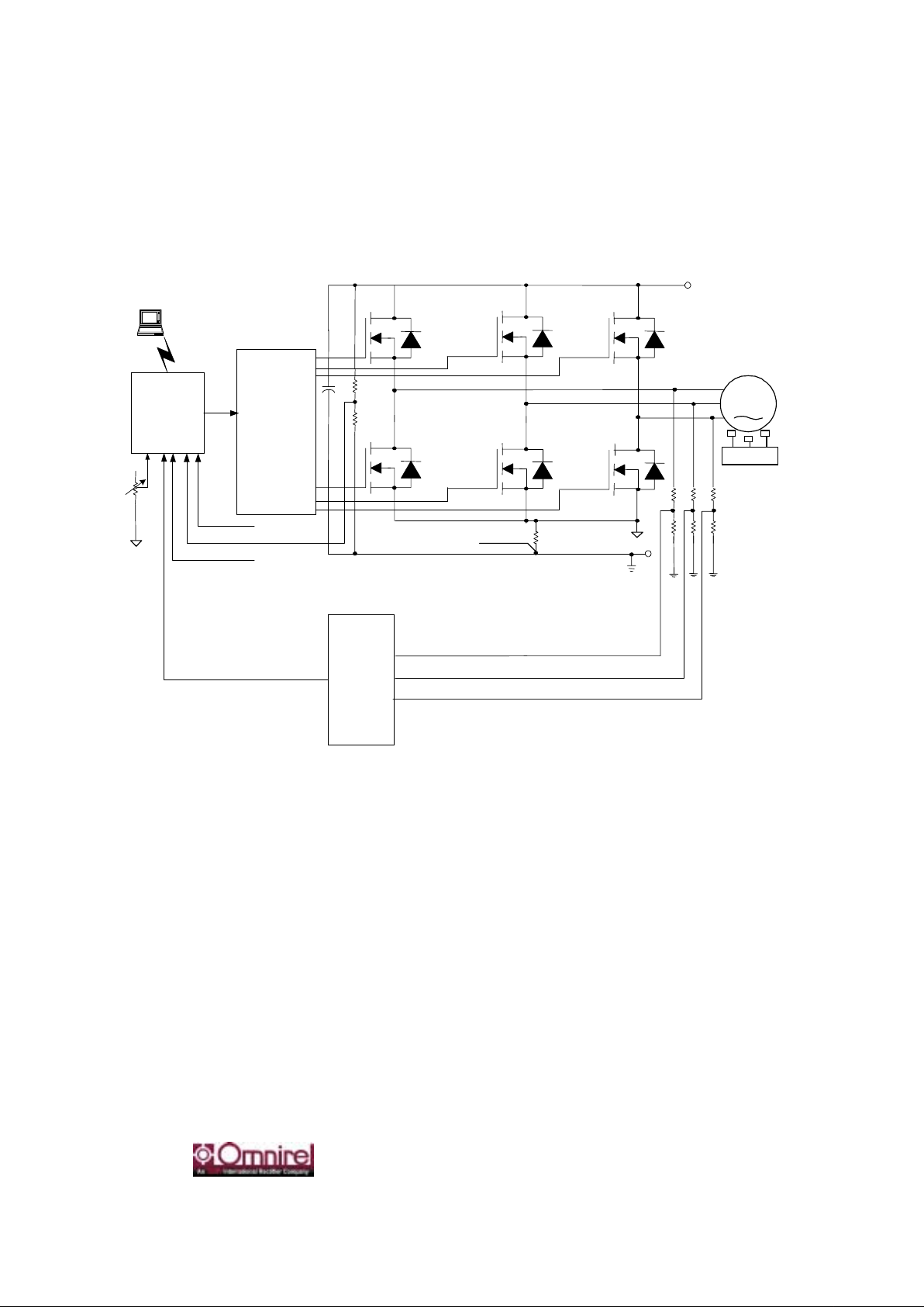
SIMPLIFIED BLOCK DIAGRAM
28V
DSP
Control
&
Interface
Phase
Voltage
Sense
Bus Voltage Sense
Va
Vb
Vc
6
3
M
HV IC Driver
+
-
PC
Hall Inputs
Hall Effect Sensor
Outputs
Current Sense
Current Sense

OMC510
Rev 03 09/27/00
205 Crawford Street • Leominster MA 01453 • Phone: 978 534 5776 • Fax: 978 537 4246 • www.omnirel.com
3
CHARACTERISTICS
Maximum Ratings
Peak Motor Supply Voltage V pk 32
Input Voltage (Analog/Digital) V -0.3 to +3.3 / -0.3 to +5.3
Operating Ambient Temperature °C 0 to +85
Storage Temperature °C -20 to +125
Nominal Power Ratings
Module Thermal & Mechanical Characteristics
Motor Supply Voltage VDC 28 Thermal Resistance
(Junction to Ambient)
°C/W 55
Continuous Current A
RMS
7
Max. Ambient
Temperature
°C
85
Current Overload
%
200 for 3 Sec;
150 for 1 min.
Dimensions (Ø) in./mm 2.50 / 63.5
PERFORMANCE SPECIFICATIONS
Speed Regulatio n: + 2 RPM
Speed Accuracy: +
0.1 %
Velocity Bandwidth: > 100 Hz
Constant Torque/
Speed Range: 50:1
Starting Torque: Start into locked rotor
Torque Response: 1.5 mSec

OMC510
Rev 03 09/27/00
205 Crawford Street • Leominster MA 01453 • Phone: 978 534 5776 • Fax: 978 537 4246 • www.omnirel.com
4
FUNCTIONAL DESCRIPTION
Inverter
The three-phase inverter consists of power MOSFETs which utilize advanced processing techniques to
9876s controlled to regulate the shaft speed with a Proportional-Integral (PI) regulator.
Current Sense
A single precision current sense resistor (1% tolerance), combined with a sophisticated algorithm, eliminates
the need for separate phase current sense resistors while still providing disturbance torque information to
improve the efficiency and robustness of the system.
Gate Drive
The gate drive section incorporates high speed power MOSFET drivers with independent high and low side
referenced output channels. The gate driver design, in conjunction with the inverter design, pr ovides for lo w
noise inverter operatio n.
Protection
Protection from short circuit conditions is provided by disabling the controller without damage to the
inverter. Under-voltage protection is provided in the gate drive section thus preventing damage to the
inverter due to insufficient gate drive voltage.
PWM System
Space Vector Modulation (SVM) is employed to provide better bus utilization, lower torque ripple, and
lower commutation losses than the standard sinusoidal PWM method. In addition, other benefits of SVM
versus the sinusoidal PWM method include ease of control and quicker response.
Motor Control Algorithms
The OMC510 can be configured for trapezoidal drive using either Hall effect sensors for absolute rotor
position feedback or a sensorless Back-EMF zero crossing detection scheme. Consult the factory for
ordering information.
Speed Regulator
The OMC510 accepts speed commands from either an isolated RS-232 port or an analog input (0 to 3V).
The speed command is compared with the estimated shaft speed and the motor torque is controlled to
regulate the shaft speed with a Proportional-Integral (PI) regulator.

OMC510
Rev 03 09/27/00
205 Crawford Street • Leominster MA 01453 • Phone: 978 534 5776 • Fax: 978 537 4246 • www.omnirel.com
5
I/O & RS-232 SPECIFICATIONS
Analog Inputs
1 analog input—0 to 3V input with 10-bit resolution. This input is the speed input.
Logic Inputs
2 logic inputs—2V threshold. These inputs are the direction and reset inputs.
RS-232 Communications
All control functions and data are available t hrough an isolated RS-232 port. A serial cable,
complete with isolated RS-232 circuitry can be provided by the factory. Consult the factory for
details.
MODE of OPERATION
Speed Mode
The OMC510 accepts speed commands from either an isolated RS-232 port or an analog input. The speed
command is compared with the estimated shaft speed and the motor torque is controlled to regulate the shaft
speed with a Proportional-Integral (PI) regulator
.
PINOUT
PIN # NAME
J1-1 Direction
J1-2 Speed In
J1-3 Reset
J1-4 Aux PWM
J1-5 Logic Gnd
J1-6 TFS1
J1-7 RFS1
J1-8 +5V
J1-9 Logic Gnd
J1-10 Reset RS232
J1-11 DR1B
J1-12 Logic Gnd
J1-13 DT1
J2-1 +15V
J2-2 HALL 1
J2-3 HALL 2
J2-4 HALL 3
J2-5 N/C
J2-6 Logic Gnd
VBUS Voltage Bus
BRTN Bus Return
PH A Phase A
PH B Phase B
PH C Phase C

OMC510
Rev 03 09/27/00
205 Crawford Street • Leominster MA 01453 • Phone: 978 534 5776 • Fax: 978 537 4246 • www.omnirel.com
6
PIN DESCRIPTIONS / FUNCTIONALITY
Direction (J1-1)—This logic input is used to select the motor direction.
Speed In (J1-2)—This input is the analog command input to the OMC510.
Reset (J1-3)— A logic low at this input initiates a complete hardware reset of the DSP.
Aux_PWM (J1-4)—This output is an auxiliary PWM output.
Logic_Gnd (J1-5)—This pin provides the reference point for the command section.
TFS1 (J1-6)—This pin is left open during normal operation. It is dedicated for engineering purposes only.
RFS1 (J1-7)—This pin is left open during normal operation. It is dedicated for engineering purposes only.
+5V (J1-8)—This supply is provided for the RS-232 interface. Note that an isolated RS-232 interface is
offered with the OMC510. Consult the factory for more information.
Logic_Gnd (J1-9)—This pin provides the reference point for the +5V supply.
Reset_RS-232 (J1-10)— A logic low at this input initiates a complete hardware reset of the DSP. This reset
is provided through the RS-232 interface.
DR1B (J1-11)—This pin is dedicated as the data receive pin for the RS-232 interface. Note that an isolated
RS-232 interface is offered with the OMC510. Consult the factory for more information.
Logic_Gnd (J1-12)—This pin provides the reference point for the RS-232 interface.
DT1 (J1-13)—This pin is dedicated as the data transmit pin for the RS-232 interface. Note that an isolated
RS-232 interface is offered with the OMC510. Consult the factory for more information.
+15V (J2-1)—This supply is provided for the Hall effect sensor bias.
Hall_1 (J2-2)—This pin is dedicated to the phase A Hall effect sensor output.
Hall_2 (J2-3)—This pin is dedicated to the phase B Hall effect sensor output.
Hall_3 (J2-4)—This pin is dedicated to the phase C Hall effect sensor output.
Logic_Gnd (J2-6)—This pin provides the reference point for the +15V supply.
Voltage Bus (VBUS)—This terminal is connected to the positive terminal of the 28V supply.
Bus Return (BRTN)—This terminal is connected to the negative terminal of the 28V supply.
Phase A (PH_A)—This terminal is connected to the phase A motor lead.
Phase B (PH_B)—This terminal is connected to the phase B motor lead.
Phase C (PH_C)—This terminal is connected to the phase C motor lead.

OMC510
Rev 03 09/27/00
205 Crawford Street • Leominster MA 01453 • Phone: 978 534 5776 • Fax: 978 537 4246 • www.omnirel.com
7
APPLICATION NOTE
SETUP
The OMC510 is a DSP-based motor controller providing speed control proportional to the command input
voltage. This command can be provided by way of either an analog or a digital interface. The Figure 1-Interconnection Diagram is representative of a typical configuration.
The OMC510 provides two micro-miniature 1.25mm headers (J1 and J2) for easy interface to command and
control (J1) and to the Hall effect sensors (J2). To mate with the headers, reference Molex receptacle
housing part numbers 51021-1300 (mate to J1) and 51021-0600 (mate to J2), and crimp terminal series
50058. An accessory cable for command and control, including an in-line isolated RS-232 interface, can be
provided. Consult the factory for details. To interface with the 28V power supply and the motor phase leads,
plated through holes, sized to accommodate up to #18 AWG wire, are provided for solder termination.
OPERATION
The OMC510 is a DSP-based motor controller providing speed control proportional to the command input
voltage (0 to 3V). The OMC510 is configured for trapezoidal commutation via Hall effect sensor feedback.
In this configuration, the Hall effect sensor outputs provide discrete absolute rotor position for commutation.
The Hall effect sensor outputs are fed into the control port, level shifted onboard from 15V to 5V, then fed
directly into the DSP. Based on this information, velocity is determined.
The OMC510 requires a single ended 28V supply. The logic voltage supplies (15V and 5V) are derived
onboard. The OMC510 will accommodate either an analog or digital command input. For the latter, a serial
port is provided onboard to interface with an isolated RS-232 communications port. The OMC510 provides
direction control as well as current limit for over-current protection. The Direction input is set by the user as
either a logic high or a logic low, and the current limit is set onboard. If the user interface requires a system
reset, a logic low is required at the Reset input to initiate a hardware reset. Otherwise, a 10k pull-up resistor
is provided onboard.
OMC510
Rev 03 09/27/00
205 Crawford Street • Leominster MA 01453 • Phone: 978 534 5776 • Fax: 978 537 4246 • www.omnirel.com
8
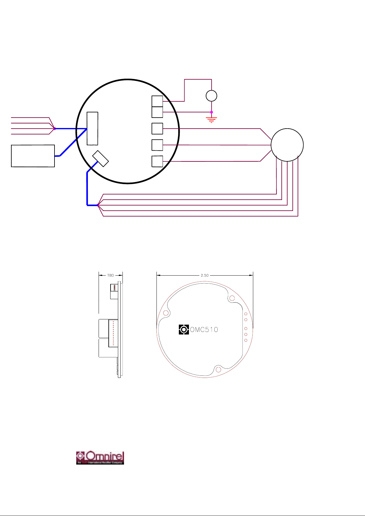
FIGURE 2 --MECHANICAL OUTLINE
Motor
PH_B
J2
+
Hall_1
Hall Sensors
Hall_3
Direction (1)
Logic_Gnd (5)
V
BUS
PH_C
Speed In (2)
RS-232
(Optional)
Hall_2
Logic_Gnd
BRTN
28V
OMC510
J1
PH_A
Reset (3)
Isolated
Interface
+15V
FIGURE 1 --INTERCONNECTION DIAGRAM
 Loading...