


OMNIREL OM4216SA, OM4203SA, OM4203RA, OM4216RA, OM4216DA Datasheet
...
3.2 - 19
3.2
4 11 R4
Supersedes 1 07 R3
HERMETIC TO-254 SCHOTTKY CENTER-TAP
RECTIFIER
FEATURES
• Very Low Forward Voltage
• Fast Switching Speed
• Hermetic Metal Package, TO-254 Outline
• Low Thermal Resistance
• Isolated Package
• Ceramic Feedthroughs Available
• Available Screened To MIL-S-19500, TX, TXV, And S Levels
DESCRIPTION
This product is specifically designed for use at power switching frequencies in excess
of 100 kHz. The product combines two Schottky-barrier diodes in a center-tap
configuration in a single package, simplifying installation, reducing heat sink
hardware, and the need to obtain matched components. The device is ideally suited
for demanding applications where small size and hermetically sealed package is
required. Common anode configuration also available.
ABSOLUTE MAXIMUM RATINGS (T
C
= 25°C) Per Diode
Peak Inverse Voltage............................................45, 60, 100 V
Maximum Average DC Output Current ...................................12.5 A
Non-Repetitive Peak Surge Current (8.3 mS)..............................100 A
Peak Reverse Transient Current ...........................................2 A
Storage Temperature Range ................................- 55° C to + 175° C
Junction Operating Temperature Range.......................- 55° C to + 150° C
Package Thermal Resistance, Junction-to-Case ........................1.7° C/W
OM4216SA/RA/DA
25 Amp, 45, 60 and 100 Volt Schottky Rectifier
OM4203SA/RA/DA
OM4215SA/RA/DA
PIN CONNECTION
123
COMMON
ANODE
COMMON
CATHODE
DOUBLER
1
3
2
1
3
2
1
2
3
SCHEMATIC
Common cathode is standard. Contact the factory for performance
characteristics for common anode and doubler.
Standard Products are supplied with glass feedthroughs.
For ceramic feedthroughs, add the letter “C” to the part number.
Example - OMXXXXCSA
Z-Tab package also available.
OMXXXXRA OMXXXXSA
OMXXXXDA
205 Crawford Street, Leominster, MA 01453 USA (508) 534-5776 FAX (508) 537-4246
3.2
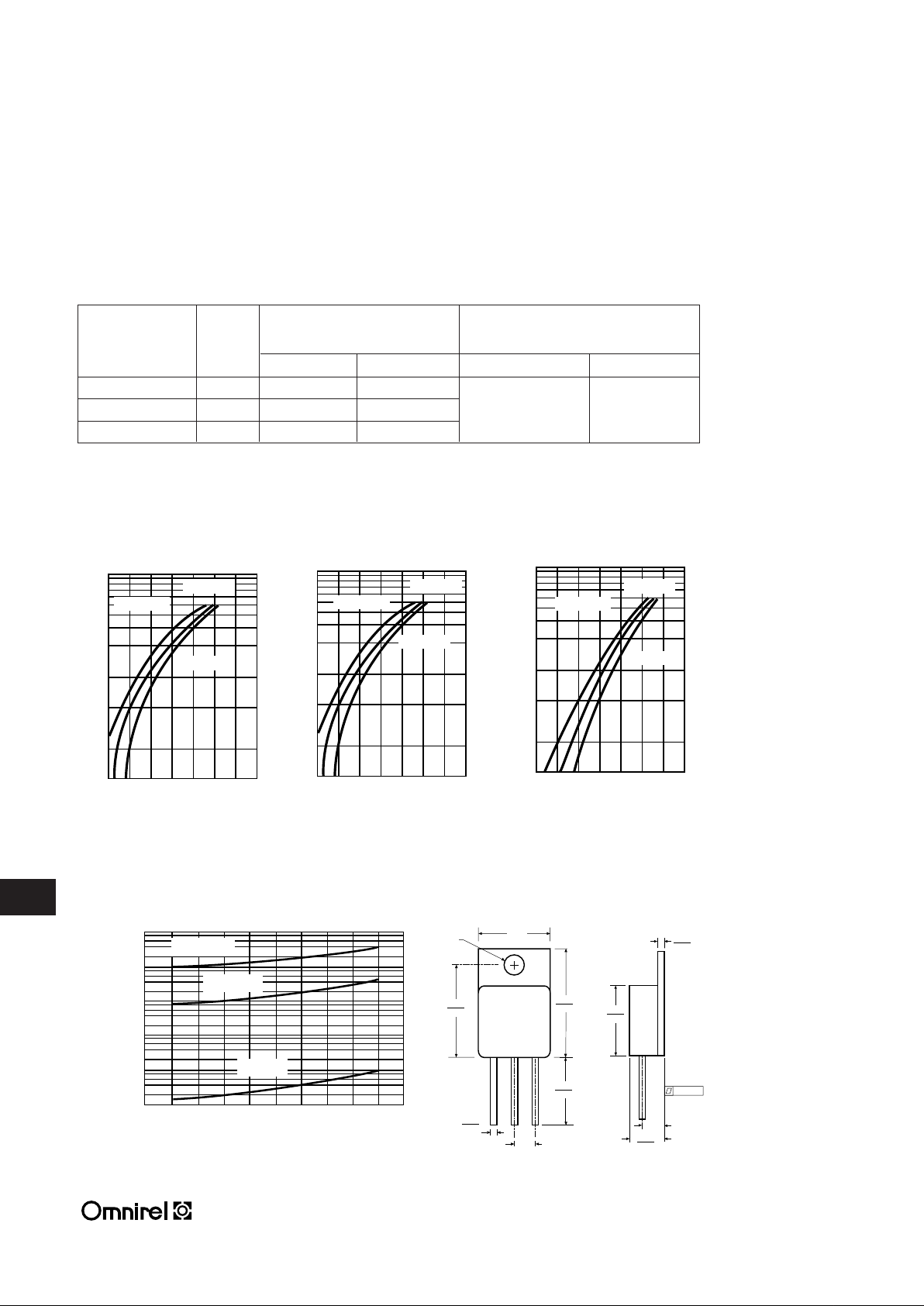
OM4203SA/RA/DA OM4215SA/RA/DA OM4216SA/RA/DA
.5 .6 .7 .8 .9 1.0
100
50
30
20
10
5
2
.5 .6 .7 .8 .9 1.0
.5 .6 .7 .8 .9 1.0
100
50
30
20
10
5
2
.5 .6 .7 .8 .9 1.0
.144 DIA.
.050
.040
.260
.249
.685
.665
.800
.790
.545
.535
.550
.510
.045
.035
.550
.530
.150 TYP.
.150 TYP.
.005
25°C
MECHANICAL OUTLINE
TYPICAL FORWARD VOLTAGE
OM4203SA
Maximum Forward Maximum
Part No. PIV Voltage @ IF= 12.5A
(1)
Reverse Current
TC= 25°C TC= 125°C TC= 25°C TC= 125°C
OM4203XX 45 .72 V .64 V
OM4215XX 60 .80 V .70 V 2mA 40mA
OM4216XX 100 .90 V .82 V
.5 .6 .7 .8 .9 1.0
100
50
30
20
10
5
2
.5 .6 .7 .8 .9 1.0
100
40
20
10
4.0
2.0
1.0
0.4
0.2
0.1
0.04
0.02
0.01
0.004
0.002
0.001
010
20 30 40
50
TYPICAL REVERSE CURRENT
OM4203SA
I
R
- REVERSE CURRRENT (mA)
VR- REVERSE VOLTAGE (VOLTS)
I
F
- INSTANTANEOUS FORWARD CURRRENT (AMPS)
TC= 125°C
TJ= 150°C
TJ= 100°C
TJ= 25°C
TC= 25°C
TC= -55°C
TC= 125°C
TC= 25°C
TC= -55°C
TC= 125°C
TC= 25°C
TC= -55°C
TYPICAL FORWARD VOLTAGE
OM4215SA
I
F
- INSTANTANEOUS FORWARD CURRRENT (AMPS)
TYPICAL FORWARD VOLTAGE
OM4216SA
I
F
- INSTANTANEOUS FORWARD CURRRENT (AMPS)
ELECTRICAL CHARACTERISTICS (Per Diode)
(1) Pulse Test: Pulse Width 300µs, Duty Cycle 2.0%.
.6 .7 .8 .9 1.0 1.1
.6 .7 .8 .9 1.0 1.1
.6 .7 .8 .9 1.0 1.1
.6 .7 .8 .9 1.0 1.1
.6 .7 .8 .9 1.0 1.1
.6 .7 .8 .9 1.0 1.1
VF- INSTANTANEOUS VOLTAGE (VOLTS)
V
F
- INSTANTANEOUS VOLTAGE (VOLTS)
V
F
- INSTANTANEOUS VOLTAGE (VOLTS)
 Loading...