


INSTRUCTIONS
BX61WI
FIXED-STAGE MOTORIZED
UPRIGHT MICROSCOPE
This instruction manual is for the Olympus Fixed-Stage Motorized Upright Microscope Model BX61WI. To ensure the safety, obtain optimum performance and to familiarize yourself fully with the use of this microscope, we recommend that you study this manual thoroughly before operating the microscope. Retain this instruction manual in an easily accessible place near the work desk for future reference.
A X 6 1 1 8

This device complies with the requirements of directive 98/79/EC concerning in vitro diagnostic medical devices. CE marking means the conformity to the directive.
NOTE: This equipment has been tested and found to comply with the limits for a Class A digital device, pursuant to Part 15 of the FCC Rules. These limits are designed to provide reasonable protection against harmful interference when the equipment is operated in a commercial environment. This equipment generates, uses, and can radiate radio frequency energy and, if not installed and used in accordance with the instruction manual, may cause harmful interference to radio communications. Operation of this equipment in a residential area is likely to cause harmful interference in which case the user will be required to correct the interference at his own expense.
FCC WARNING: Changes or modifications not expressly approved by the party responsible for compliance could void the user’s authority to operate the equipment.
BX61WI
CONTENTS
Correct assembly and adjustments are critical for the microscope to exhibit its full performance. If you are going to assemble the microscope yourself, please read Chapter 9, “ASSEMBLY” (pages 42 to 49) carefully. For the modules provided with instruction manuals, also read the assembly procedures in their instruction manuals.
IMPORTANT — Be sure to read this section for safe use of the equipment. — |
1-3 |
|
|
|
|
|
|
|
1 |
MODULE NOMENCLATURE |
4 |
|
|
|
|
|
|
2 |
CONTROLS |
5-11 |
|
|
|
3TRANSMITTED LIGHT BRIGHTFIELD OBSERVATION PROCEDURE 12, 13
4 |
USING THE CONTROLS |
|
14-23 |
||
|
|
|
|
|
|
|
4-1 |
Microscope Frame .................................................................................................................................................................. |
|
14, 15 |
|
|
|
1 |
Voltage Indication |
2 |
Transmitted/Reflected Light Switch |
|
|
3 |
Light Preset Switch |
4 |
Using the Filter Turret |
|
4-2 |
Focusing Block............................................................................................................................................................................. |
|
15, 16 |
|
|
|
1 |
Replacing the Focus Adjustment Knob |
2 |
F/C Button |
|
|
3 |
Objective Up/Down Buttons |
4 |
Objective Escape/Return Button |
5Using the Frost Filter Insertion/Removal Lever
4-3 |
Stage (IX-SVL2) .............................................................................................................................................................................. |
|
17, 18 |
|
|
1 |
Placing the Specimen |
2 |
Moving the Specimen |
|
3 |
Setting the Grounding |
4 |
Adjusting the X-Axis/Y-Axis Knob Rotation Tension |
|
5 |
Using the Light Shielding Sheet |
6 |
Lowering the Stage Height |
4-4 |
Revolving Nosepiece .................................................................................................................................................................... |
|
18 |
|
1Switching the Objectives
4-5 Observation Tube .................................................................................................................................................................... |
|
19, 20 |
|
1 |
Adjusting the Interpupillary Distance |
2 |
Adjusting the Diopter |
3 |
Using the Eye Shades |
4 |
Using Eyepiece Micrometer Disks |
5Selecting the Light Path of Trinocular Tube
4-6 |
Condenser ........................................................................................................................................................................................ |
21 ,22 |
|
1 Centering the Condenser |
2 Oblique Illumination (WI-OBCD) |
4-7 |
Water Immersion Objectives .............................................................................................................................................. |
23 |
1Using Water Immersion Objectives (Water Immersion Cap)

|
|
|
|
|
|
|
|
|
|
|
|
|
|
|
5 |
OTHER OBSERVATION METHODS |
24-35 |
|||
|
|
|
|
|
||
|
|
5-1 |
Differential Interference Contrast Observation.............................................................................. |
24-28 |
||
|
|
|
1 |
Attaching the Analyzer |
2 Attaching the Polarizer |
|
|
|
|
3 |
Attaching the DIC Prisms (for Revolving Nosepiece) |
|
|
|
|
|
4 |
Attaching the DIC Prisms (for Condenser) |
|
|
|
|
|
5 |
Adjusting the Polarizer Position (except the U-UCD8) |
|
|
|
|
|
6 |
Observation Method |
|
|
|
|
5-2 |
Reflected Light Fluorescence Observation................................................................................................... |
29 |
||
|
|
5-3 |
Infrared Light (IR)/Differential Interference Contrast (DIC) Observation ............... |
29-32 |
||
|
|
|
1 |
Introduction |
2 Attaching the IR Modules |
|
|
|
|
3 |
DIC Observation Using IR |
|
|
5-4 Macro Reflected Light Fluorescence Observation ................................................................. |
33-35 |
|
1 Introduction |
2 Attaching the Modules |
|
|
3 |
Filter Characteristics of Fluorescence Mirror Units |
|
|
4 |
Fabricating Optional Mirror Units |
|
|
|
|
|
6 |
TROUBLESHOOTING GUIDE |
36-38 |
|
|
|
|
|
|
|
|
|
7 |
SPECIFICATIONS |
39, 40 |
|
|
|
|
|
|
|
|
|
8 |
OPTICAL CHARACTERISTICS |
41 |
|
|
|
|
|
9ASSEMBLY — See this section for the replacement of the light bulb. — 42-49
10 LAMP HOUSING INSPECTION SHEET |
50 |
|
|

BX61WI
IMPORTANT
This microscope employs a UIS2 (UIS) (Universal Infinity System) optical design, and should be used only with modules designed for the BX2 series (which belong to the Olympus BX series).
For the applicable modules, please consult Olympus or the latest catalogues. Less than optimum performance may result if inappropriate module combinations are used.
Configuration of Instruction Manuals
Since this microscope is expandable to a variety of systems, separate instruction manuals are prepared so that the user has to read only the manuals according to the user’s own system.
Manual Name |
Main Contents |
BX61WI |
Observation procedures including transmitted light brightfield, |
|
DIC and IR observations |
BX-UCB/U-HSTR2 |
Functions of the Control Box (incorporating the power supply) |
|
and Hand Switch |
BX2 Software for PC (CD-ROM) |
Methods of PC control of functions |
* BX2-BSW Ver. 03.01 or higher |
* Normal operation is not available unless the specified software is used. |
TH4 |
External halogen lamp power supply |
|
|
BX-RFAA/BX-URA2/BX-RFA |
Reflected light fluorescence observation procedure |
|
|
U-FWT/FWR/FWO |
Motorized filter wheels (The U-FWT cannot be used with this |
|
microscope.) |
WI-DPMC |
Information on the dual-port magnification changer tube |
WI-XYM/XYS |
Information on the XY mover and bridge stage |
|
|
WI-SSNP |
Information on the swing-slide revolving nosepiece |
|
|
SAFETY PRECAUTIONS
1.After the equipment has been used in an observation of a specimen that is accompanied with a potential of infection, clean the parts coming in contact with the specimen to prevent infection.
·Moving this product is accompanied with the risk of dropping the specimen. Be sure to remove the specimen before moving this product.
·In case the specimen is damaged by erroneous operation, promptly take the infection prevention measures.
·The product becomes unstable if its height is increased by an accessory mounted on it. In this case, take anti-toppling measures to prevent the specimen from being dropped when the product topples down.
2.Culture liquid or water spilt on the stage, condenser or microscope may damage the equipment. Immediately wipe the liquid or water off if it is spilt on them.
3.If a foreign object is caught during motorized focusing operation, there will be an error in the focusing block and the motorized focusing operation will be suspended.
Recovery procedure
·If there is no error in motorized operation, the caught object can be removed by turning the focusing knob.
·If there is an error in motorized operation, the focusing knob becomes inoperable. Disassemble the relevant modules to remove the caught object. Replace the relevant modules afterward.
·Turn off the power and then on again. The system will restart unless there is a malfunction in the motor.
4.Emergency stop of focus operation is possible by turning the focus adjustment knob (or dial) on the microscope frame or on the U-FH (in either direction), or by pressing the FOCUS control button (  ,
,  , F/C or ESC), after focus operation has been activated (except when data is being downloaded to a PC).
When the BX-UCB control box’s main switch is set to “ I ” (ON), the focus operates automatically (the objective raises once and then returns to the original position) for initialization. (It takes about one minute.)
If the above emergency procedure is performed during this automatic focus operation, the microscope stops operating. Should this happen, set the main
switch to “ ” (OFF) and then “ I ” (ON) again. |
1 |
1
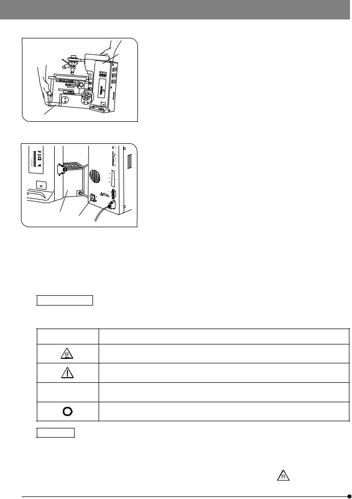
Fig. 1
4 3
Fig. 2
Safety Symbols
5.When moving the microscope, disconnect the reflected light illuminator, observation tube and transmitted light lamp housing and carefully carry
2the microscope by the base (front edge) 1 and the grasping part on the
rear of the arm 2 as shown in Fig. 1. (Weight: approx. 15 kg.) Also be careful against slipping of hands during carrying.
#Damage to the microscope will occur if you grasp it by other parts including the stage, focus adjustment knob, etc.
6.The surfaces of the lamp housing on the rear of the microscope will become extremely hot during operation. When installing the microscope, make sure to allow ample free space (10 cm or more) around and in particular above the lamp housing.
7.When installing the microscope, route the power cord away from the
lamp housing. Should the power cord come in contact with the hot lamp housing, the power cord could melt and cause electric shock.
8 To avoid potential shock hazards and burns when replacing the light bulb, set the main switch ³ to “ ” (OFF) then disconnect the power cord from the wall outlet in advance. Whenever you replace the bulb during use or right after use, allow the lamp housing | and bulb to cool before touching. (Fig. 2)
Designated |
12V100WHAL (PHILIPS 7724) |
Bulbs |
12V50WHAL-L (LIFE JC) |
|
|
#The microscope also incorporate a fuse (this should be replaced by the manufacturer or an Olympus-authorized agent).
9.Always use the power cord provided by Olympus. If the proper power cord is not used, product safety performance cannot be warranted.
10.Always ensure that the grounding terminal of the microscope and that of the wall outlet are properly connected. If the equipment is not grounded, Olympus can no longer warrant the electrical safety performance of the equipment.
11.Never insert metallic objects into the air vents of the microscope frame as this could result in electrical shock, personal injury and equipment damage.
The following symbols are found on the microscope. Study the meaning of the symbols and always use the equipment in the safest possible manner.
Symbol |
Explanation |
|
|
Indicates that the surface becomes hot, and should not be touched with bare hands.
Before use, carefully read the instruction manual. Improper use could result in personal injury to the user and/or damage to the equipment.
lIndicates that the main switch is ON.
Indicates that the main switch is OFF.
Warnings
Warning engraving is placed at parts where special precaution is required when handling and using the microscope. Always heed the warnings.
Warning engraving |
Lamp housing (U-LH100-3/U-LH100IR) |
||
position |
(Warning against high temperature) |
|
|
|
|||
|
|
|
|
2

BX61WI
1Getting Ready
1.A microscope is a precision instrument. Handle it with care and avoid subjecting it to sudden or severe impact.
2.The U-SWTR-3 super-widefield observation tube (FN 26.5) cannot be used with the BX61WI microscope.
3.The BX61WI microscope can be used with an intermediate attachment (such as a BX-RFAA, BX-URA2 or BX-RFA reflected light illuminator, U-ECA or U-CA magnification changer, etc.).
Two intermediate attachments can be used only in the following conditions:
·The U-CA or U-ECA magnification changer or U-FWO filter wheel can be mounted as the second attachment.
·When a TV adapter with 1X or higher power is used, 2/3-inch CCD TV observation is possible.
·The peripheral areas of the field of view may be obscured or cut off in binocular observation using the U-TR30-2, U-ETR3 or U-TR30IR (FN 22) super-widefield observation tube.
4.In IR (infrared) observation, the U-CA or U-ECA magnification changer can be used only when the U-ETR3 or U-TR30IR observation tube is used.
5.In photomicrography with visible light, correct exposure may be impossible if the microscope is set for IR observation. Be sure to engage the provided IR cut filter (light blue) before photomicrography.
6.When the XLUMPlanFLN20XW objective is used, only the U-TV1X, U-TVCAC, U-PMTVC2XIR or U-PMTVC4XIR TV adapter can be used.
7.Do not attempt to remove or loosen the click springs and screws. Otherwise, Olympus can no longer warrant the performance of the microscope.
The clicking force of the revolving nosepiece has been set weak in order to reduce vibrations during objective switching. To reproduce the correct click position, switch the objectives gently by operating the lever.
8.Caution for use of the U-ETR3 upright trinocular tube:
When the aperture stop of the condenser is reduced using a reflected light fluorescence illuminator and the LUMPlanFl60XW objective, part of the observed field of view may be obscured slightly. This is due to the reduction of the light intensity in the field of view due to the narrow aperture and is not due to a defective optical adjustment of the microscope.
This phenomenon does not affect the photomicrography or TV camera light path.
2Maintenance and Storage
1.To clean the lenses and other glass components, simply blow dirty away using a commercially available blower and wipe gently using a piece of cleaning paper (or clean gauze).
If a lens is stained with fingerprints or oil smudges, wipe it gauze slightly moistened with commercially available absolute
alcohol.
 Since the absolute alcohol is highly flammable, it must be handled carefully.
Be sure to keep it away from open flames or potential sources of electrical sparks --- for example, electrical equipment that is being switched on or off, which could cause ignition of a fire.
Also remember to always use it only in a well-ventilated room.
2.Do not attempt to use organic solvents to clean the microscope components other than the glass components. To clean them, use a lint-free, soft cloth slightly moistened with a diluted neutral detergent.
3.Never attempt to disassemble any part of the microscope.
4.When not using the microscope, make sure to set the main switch to “ ” (OFF), confirm that the lamp housing is cool enough and cover the microscope with the provided dust cover.
3Caution
If the microscope is used in a manner not specified by this manual, the safety of the user may be imperiled. In addition, the equipment may also be damaged. Always use the equipment as outlined in this instruction manual.
The following symbols are used to set off text in this instruction manual.
 : Indicates that failure to follow the instructions in the warning could result in bodily harm to the user and/or damage to equipment (including objects in the vicinity of the equipment).
# : Indicates that failure to follow the instructions could result in damage to equipment. } : Indicates commentary (for ease of operation and maintenance).
4Intended use
This instrument has been designed to be used to observe magnified images of specimens in routine and research applications.
Do not use this instrument for any purpose other than its intended use.
3
 MODULE NOMENCLATURE
}The modules shown below are only the representative modules. As there are other modules which can be combined with the microscope but are not shown below, please also refer to the latest Olympus catalogues or your dealer.
The Z board combined with the BX61WI must always be the U-ZPCB(T2). Also note that the DIP switch
CAUTION
setting should be changed when the Z board is used (see page 44).
Trinocular Observation Tube
·U-TR30-2 (FN 22)
·U-TR30IR (FN 22)
·U-ETR3 (FN 22)
Revolving Nosepiece
· WI-SRE3
· WI-SNPXLU2
·U-SLRE
·WI-SSNP
(with revolving arm)
Revolving Arm WI-NPA
Power Supply Unit
U-RFL-T
Cross Stage IX-SVL2 or bridge stage WI-XYS
Fixed-Stage Adapter
WI-FSH
Condenser
· WI-UCD · WI-DICD · WI-OBCD · U-UCD8 · U-SC3
· U-AAC
· U-AC2
Transmitted Arm BX-ARM
or Reflected Light Fluorescence Illuminator
· BX-RFAA · BX-URA2 · BX-RFA
Reflected Light Mercury Lamp Housing
· U-LH100HG
· U-LH100HGAPO
Microscope Frame BX61WIF
Transmitted Light Lamp Housing
· U-LH100-3 · U-LH100IR
Control Box BX-UCB
The U-ZPCB(T2) Z Board can be mounted here.
|
Focus Adjustment Knob Interface |
|
U-IFFH |
|
Focus Adjustment Knob Unit U-FH |
|
Objectives |
· MPLN5X |
Hand Switch U-HSTR2 |
|
·UMPlanFLN10XW/20XW
·LUMPlanFLN40XW/60XW
·LUMFLN60XW
·LUMPlanFl100XW
·XLUMPlanFLN20XW (exclusively for use with the WI-SNPXLU2)
·XLFluor2X/340 (exclusively for use with the U-SLRE)
·XLFluor4X/340 (exclusively for use with the U-SLRE)
4
BX61WI
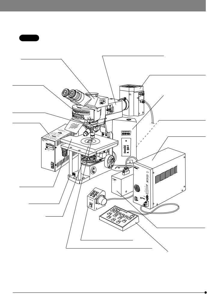
CONTROLS
}If you have not yet assembled the microscope, read Chapter 9, “ASSEMBLY” (pages 42 to 49).
Reflected light fluorescence illuminator
(See the separately provided instruction manual.)
Light path selector knob (Page 20)
Interpupillary distance scale (Page 19)
Diopter adjustment ring (Page 19)
Mercury lamp power supply unit
(See the separately provided instruction manual.)
Y-axis knob (Page 17)
X-axis knob (Page 17)
Stage center plate
Centering knobs
(Storage position)
Light intensity control buttons (Page 14)
Objective down button (Page 16)
Reflected light mercury lamp housing
(See the separately provided instruction manual.)
Allen screwdriver
(Storage position)
Lamp voltage indicator (Page 14)
Transmitted/reflected light switch (Page 14)
(For halogen bulb)
PHOTO indicator (Page 14)
Control Box BX-UCB
(See the separately provided instruction manual.)
Focus adjustment dial (Page 15)
Objective up button (Page 16)
}The descriptions on the left side of the microscope frame, filter turret, revolving nosepiece, condenser, etc. will be given in the subsequent pages.
5

Left Side View of Microscope Frame
Focus adjustment knob (Page 15)
Objective escape/return button (Page 16)
F/C button (Page 16)
F: Fine adjustment
C: Coarse adjustment
Frost filterinsertion/removal lever (Page 16)
Light Preset switch (Page 14)
Lamp ON-OFF switch
Filter Turret
Polarizer positions* (Page 24)
Accepts a 32PO or 32POIR polarizer.
Indication label attaching frame
Filter positions
Accepts 32 mm filters with thickness of no more than 6 mm.
Polarizer clamping knob (Page 24)
Polarizer push rings (Page 15)
Made of white plastic
* Accepts the combination of a
Polarizer rotating dials
polarizer push ring and a 32 mm
(Page 28)
filter. The thickness should be no more than 6 mm.
Slider insertion/removal stopper (Page 15)
Filter frame reinforcing ring (Page 46)
Filter slider (Page 15)
IR filter insertion position
Accepts a 32BP775, 32IR900 or a 32 mm filter with thickness of no more than 5.3 mm.
6
BX61WI
Revolving Arm WI-NPA
#Note that the revolving arm can be mounted only before the reflected light illuminator or transmitted light arm and the IX-SVL2 stage are mounted (page 45).
}This revolving arm accepts the U-SLRE, WI-SNPXLU2 or WI-SRE3 revolving nosepiece.
Grounding screw hole (M3)
Light shielding tube retaining screw
Revolving nosepiece mount dovetail |
Microscope frame mount dovetail |
Revolving nosepiece clamping screw
Sliding Revolving Nosepiece U-SLRE |
|
Single-Position Revolving Nosepiece XLU |
|
|||
|
|
WI-SNPXLU2 |
|
|
|
|
|
|
|
|
|||
|
|
|
|
|
|
|
Switching lever |
|
|
DIC mount hole |
|
|
|
|
|
|
(Page 25) |
|
Drop prevention screw |
|
|
|
|
|
|
|
|
|
UIS2 (UIS) |
XLU objective mount screw |
|
XLFluor objective mount screw |
M 25 mm, pitch 0.75 mm |
||
objective |
|||
M 34 mm, pitch 1 mm |
|
||
mount screw |
|
||
|
|
UIS2 (UIS) objective mount screw |
|
|
|
RMS Adapter WI-RMSAD |
|
Swinging Revolving Nosepiece |
WI-SRE3 |
|
|
|
|
Confocality correction washer |
|
Swing lever |
|
Drop prevention screw |
|
|
|
||
|
|
(Thickness 10, 30 and 50 μm, x 3 each) |
|
Centering screws |
|
DIC mount hole |
|
|
|
(Page 25) |
|
UIS objective mount screws |
|
|
|
|
|
Centering knobs |
7
Long-WD Universal Condenser WI-UCD
Aperture iris diaphragm lever (Page 22)
Quarter-wave plate clamping knob
Turret (4 positions) |
|
Optical element index |
|||
|
|
|
mount (Page 26) |
||
Quarter-wave plate rotation |
|
|
|
DIC prism replacement cover |
|
ring (Page 28) |
|
|
|
|
|
|
|
|
|
||
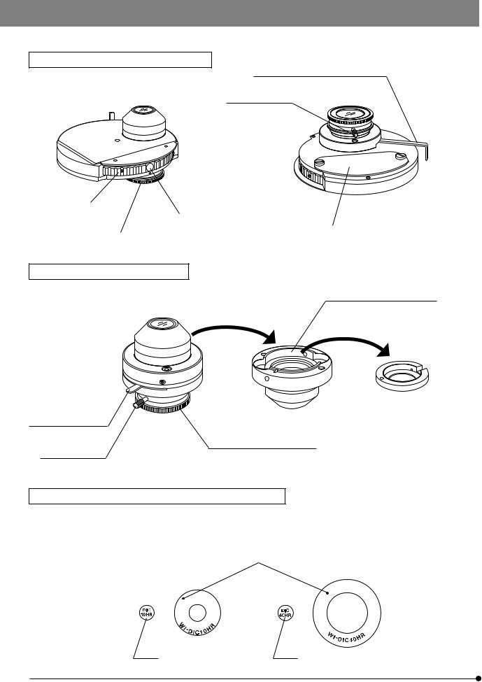
Long-WD DIC Condenser WI-DICD
DIC prism (Large) mount position
DIC prism (Small) adapter
Aperture iris diaphragm lever (Page 22)
Quarter-wave plate rotation ring Quarter-wave plate (Page 28) clamping knob
Differential Interference Contrast Prisms (For Condenser)
}The WI-UCD condenser accepts two large and two small DIC prisms while the WI-DICD condenser accepts one large or small DIC prism.
When selecting the brightfield (BF) light path using the WI-UCD, leave one DIC prism (large) mount position empty.
Positioning indices
· WI-DIC10HR
· WI-DIC40HR
· WI-DIC20HR
· WI-DIC60HR
· WI-DICXLU20HR
Index |
Index |
8
BX61WI
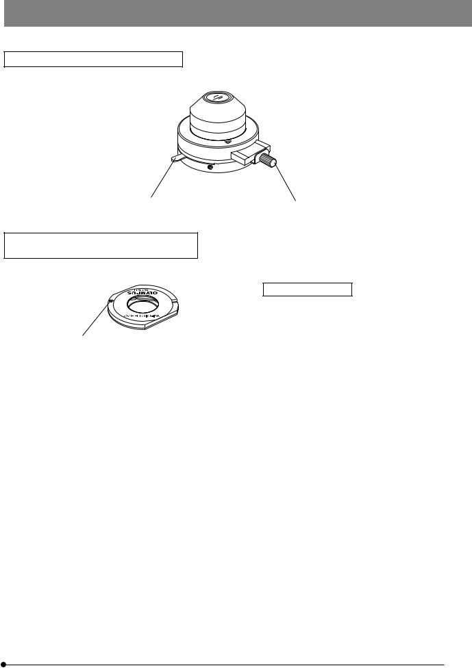
Long-WD Oblique Condenser WI-OBCD
Aperture iris diaphragm lever (Page 22)
Oblique iris insertion/removal knob (Page 22)
High-Resolution DIC Prism A |
WI-DICTHRA2 |
DIC Prism |
WI-DICT2 |
}This prism can be mounted in the DIC prism position of the WI-SNPXLU2 or WI-SRE3.
Applicable condensers
WI-DICTHRA2: WI-UCD, W-DICD
WI-DICT2: U-UCD8
Positioning pin
 Condensers and Applicable Objective Magnifications
Condenser |
Applicable Objective Magnification |
|
WI-UCD |
|
|
WI-DICD |
5X or more |
|
WI-OBCD |
|
|
|
|
|
U-UCD8 |
2X or more |
|
U-SC3 |
||
|
||
|
|
|
U-AAC |
10X or more |
|
|
|
|
U-AC2 |
5X or more |
|
|
|
9
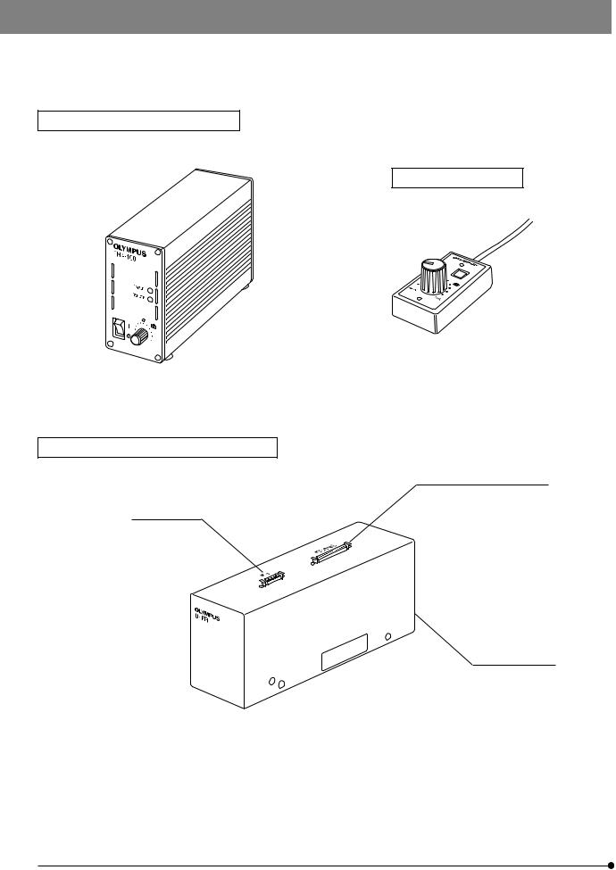
}The following modules are required to eliminate electrical noise, which may affect the potential measurement data during patch clamping.
Halogen Lamp Power Supply TH4 (See the separately provided instruction manual for details.)
Hand Switch TH4-HS
Focus Adjustment Knob Interface U-IFFH
Microscope FRAME connector
U-FH connector
BX-UCB connector
10
BX61WI
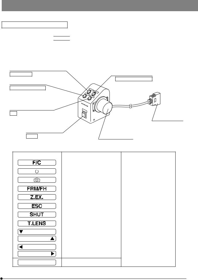
Focus Adjustment Knob Unit U-FH
The button functions described below are those when the microscope is used stand-alone. The buttons functions inside 
 are the initial setups for PC control (remote operation).
The button functions can also be assigned as required by the user. For the assignment, refer to the instructions for the BX2-BSW BX Software (Ver. 03.01 or higher).
After setting up the button functions, attach the provided stickers near the buttons. For the function abbreviations and symbols on the stickers, see the following table.
Objective escape/return button (Page 16)
Lamp ON/OFF
F/C button (Page 16)
Focusing motor ON/OFF
Objective down button (Page 16)
F/C
Transmitted/reflected light switch button (Page 14)
Option
Objective up button (Page 16)
Objective escape/shelter
Connector
Connect to the U-IFFH.
Focus adjustment knob
Abbreviations & Symbols |
Function |
Note |
|
|
|
Fine/Coarse switching |
|
|
|
|
|
|
|
Lamp ON/OFF |
|
|
|
|
|
|
|
|
|
|
|
|
|
|
|
Set/cancel photo voltage |
|
|
|
|
|
|
|
Focus adjustment knob FRAME/U-FH |
|
|
|
|
|
|
|
Z-focusing motor ON/OFF |
OFF: Electrical noise reduction |
|
|
|
|
|
|
Escape/return objective |
|
|
|
|
|
|
|
Shutter IN/OUT |
|
|
|
|
|
|
|
Condenser top lens IN/OUT |
Not used with the BX61WI. |
|
|
|
|
|
|
Up/down operation for brightness ad- |
The function name can be written |
|
|
justment, objective, etc. |
in the blank area using an oil-ink |
|
|
|
pen. |
|
|
|
|
Left/right operation of mirror unit, filter wheel, etc.
11
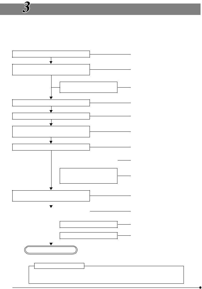
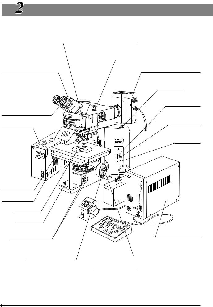
TRANSMITTED LIGHT BRIGHTFIELD
OBSERVATION PROCEDURE
}The following flow shows the operating procedure for the transmitted light brightfield observation which is the basic observation method of this microscope. The operating procedures for DIC observation, fluorescence DIC observation and IR DIC observation will be described separately in Chapter 5, “OTHER OBSERVATION METHODS” on page 24.
Set the main switch to “ I ” (ON).
Select the transmitted light illumination and adjust its brightness.
Disengage the filter from the light path.
Select the binocular light path.
Place the specimen on the stage.
Engage a low-magnification objective in the light path.
Bring the specimen in focus.
(Controls Used) |
(Page) |
@Main switch |
|
²Lamp ON-OFF switch |
|
³Transmitted/reflected light switch |
(P. 14) |
|Light intensity control buttons |
(P. 14) |
5Filter turret |
(P. 15) |
…Light path selector knob |
(P. 20) |
7X-axis and Y-axis knobs |
(P. 17) |
8Swing lever |
(P. 18) |
9Objective up/down buttons, focus |
(P. 16) |
adjustment knob/dial |
|
|
|
Adjust the brightness. |
|Light intensity control buttons |
(P. 14) |
|
|
|
||||
|
|
|
|
aBinocular tube |
(P. 19) |
|
|
|
|
||
|
|
Adjust the interpupillary distance. |
bDiopter adjustment ring |
(P. 19) |
|
|
|
Adjust the diopter. |
cCondenser height adjustment knob |
(P. 21) |
|
|
|
||||
|
|
Adjust the light axis. |
dCondenser centering knobs |
(P. 21) |
|
|
|
|
|
eField iris diaphragm ring |
(P. 21) |
Engage the objective to be used in the light |
‡Swing lever |
(P. 18) |
|||
path and bring the specimen in focus. |
9Objective up/down buttons, focus |
(P. 16) |
|||
|
|
|
|
adjustment knob/dial |
|
|
|
|
|
|
|
|
|
|
|
fAperture iris diaphragm lever |
(P. 22) |
Adjust the aperture iris and field iris diaphragms. |
|
||||
|
eField iris diaphragm ring |
(P. 21) |
|||
|
|
|
|
||
|
|
Engage the required filters. |
5Filter turret |
(P. 15) |
|
|
|
||||
|
|
Adjust the brightness. |
|Light intensity control buttons |
(P. 14) |
|
|
|
||||
|
|
|
|
|
|
Start observation.
Tip for microscope operation
In patch-clamp testing, switch the microscope controls cautiously and gently so that the patch electrodes do not slip off.
12

BX61WI
(Note) Controls with numbers inside 
 can perform the same functions as the controls with numbers inside ¦. However, the function of control
 9
9 
 is not available when the U-FH is in use.
6
b
a
8


3

 9
9 

7
cdf
9
5
e
4
9
3
9
Control Box BX-UCB
*The U-ZPCB (T2) Z board can
1 be mounted here.
See page 44 for the setup and installation of the Z board.

 9
9 

2

}Make a photocopy of the observation procedure pages and post it near your microscope.
13
 Loading...