


INSTRUCTIONS
BX51WI
FIXED-STAGE UPRIGHT
MICROSCOPE
This instruction manual is for the Olympus Fixed-Stage Upright Microscope Model BX51WI. To ensure the safety, obtain optimum performance and to familiarize yourself fully with the use of this microscope, we recommend that you study this manual thoroughly before operating the microscope. Retain this instruction manual in an easily accessible place near the work desk for future reference.
A X 7 6 5 7

BX51WI
CONTENTS
Correct assembly and adjustments are critical for the microscope to exhibit its full performance. If you are going to assemble the microscope yourself, please read Chapter 9, “ASSEMBLY” (pages 36 to 42) carefully. For the modules provided with instruction manuals, also read the assembly procedures in their instruction manuals.
IMPORTANT — Be sure to read this section for safe use of the equipment. — |
1-2 |
|||||
|
|
|
|
|
||
|
|
|
|
|
|
|
1 |
MODULE NOMENCLATURE |
|
|
3 |
||
|
|
|
|
|
||
|
|
|
|
|
||
2 |
CONTROLS |
|
|
4-7 |
||
|
|
|
||||
|
|
|
||||
3 |
TRANSMITTED LIGHT BRIGHTFIELD OBSERVATION PROCEDURE |
8, 9 |
||||
|
|
|
|
|
||
|
|
|
|
|
|
|
4 |
USING THE CONTROLS |
|
|
10-18 |
||
|
|
|
|
|||
|
4-1 |
Microscope Base, Power Supply Unit (TH4)................................................................................................ |
10 |
|||
|
|
1 |
Controlling the Light Intensity (TH4) |
2 |
Using the Filter Turret |
|
|
4-2 |
Focusing Block........................................................................................................................................................................................ |
|
|
11 |
|
|
|
1 |
Using the Pre-focusing Lever |
2 |
Using the Fine Adjustment Fast-Feed Knob |
|
|
|
3 |
Using the Frost Switching Lever |
|
|
|
|
|
4 |
Adjusting the Coarse Adjustment Knob Rotation Tension |
|
||
|
4-3 |
Stage (IX-SVL2) ............................................................................................................................................................................. |
|
|
12, 13 |
|
|
|
1 |
Placing the Specimen |
2 |
Moving the Specimen |
|
|
|
3 |
Setting the Grounding |
4 |
Adjusting the X-Axis/Y-Axis Knob Rotation Tension |
|
|
|
5 |
Using the Light Shield Sheet |
6 |
Lowering the Stage Height |
|
|
4-4 |
Revolving Nosepiece .................................................................................................................................................................... |
|
|
13 |
|
|
|
1 |
Switching the Objectives (U-SLRE, WI-SRE3) |
|
||
|
4-5 |
Observation Tube ..................................................................................................................................................................... |
|
|
14, 15 |
|
|
|
1 |
Adjusting the Interpupillary Distance |
2 |
Adjusting the Diopter |
|
|
|
3 |
Using the Eye Shades |
4 |
Using Eyepiece Micrometer Disks |
|
|
|
5 |
Selecting the Light Path of Trinocular Tube |
|
|
|
|
4-6 |
Condenser .......................................................................................................................................................................................... |
|
|
16, 17 |
|
|
|
1 |
Centering the Condenser (Field Iris Diaphragm, Aperture Iris Diaphragm) |
|
||
|
|
2 |
Oblique Illumination (WI-OBCD) |
|
|
|
|
4-7 |
Immersion Objectives .................................................................................................................................................................. |
|
|
18 |
|
1 Using Water Immersion Objectives (Water Immersion Cap for XL Objectives XL-CAP)
|
|
|
|
|
|
|
|
|
|
|
|
|
|
|
5 |
OTHER OBSERVATION METHODS |
19-30 |
|||
|
|
|
|
|
||
|
|
5-1 |
Differential Interference Contrast Observation............................................................................... |
19-23 |
||
|
|
|
1 |
Attaching the Analyzer |
2 Attaching the Polarizer |
|
|
|
|
3 |
Attaching the DIC Prisms (for Revolving Nosepiece) |
|
|
|
|
|
4 |
Attaching the DIC Prisms (for Condenser) |
|
|
|
|
|
5 |
Adjusting the Polarizer Position (except the U-UCD8) |
|
|
|
|
|
6 |
Observation Method |
|
|
|
|
5-2 |
Reflected Light Fluorescence Observation................................................................................................... |
24 |
||
|
|
5-3 |
Infrared Light (IR)/Differential Interference Contrast (DIC) Observation ............... |
24-27 |
||
|
|
|
1 |
Introduction |
2 Attaching the IR Modules |
|
|
|
|
3 |
DIC Observation Using IR |
|
|
|
|
5-4 |
Macro Reflected Light Fluorescence Observation ................................................................. |
28-30 |
||
|
|
|
1 |
Introduction |
2 Attaching the Modules |
|
|
|
|
3 Filter Characteristics of Fluorescence Mirror Units |
|
||
|
|
|
4 |
Fabricating Optional Mirror Unit |
|
|
|
|
|
|
|||
|
6 |
TROUBLESHOOTING GUIDE |
|
31-33 |
||
|
|
|
|
|
||
|
|
|
|
|||
|
7 |
SPECIFICATIONS |
|
34 |
||
|
|
|
|
|
||
|
|
|
|
|||
|
8 |
OPTICAL CHARACTERISTICS |
|
35 |
||
|
|
|
|
|
|
|
9ASSEMBLY — See this section for the replacement of the light bulb. — 36-42
PROPER SELECTION OF THE POWER SUPPLY CORD ................................................................... |
43, 44 |
10 LAMP HOUSING INSPECTION SHEET |
45 |
This device complies with the requirements of directive 98/79/EC concerning in vitro diagnostic medical devices. CE marking means the conformity to the directive.
NOTE: This equipment has been tested and found to comply with the limits for a Class A digital device, pursuant to Part 15 of the FCC Rules. These limits are designed to provide reasonable protection against harmful interference when the equipment is operated in a commercial environment. This equipment generates, uses, and can radiate radio frequency energy and, if not installed and used in accordance with the instruction manual, may cause harmful interference to radio communications. Operation of this equipment in a residential area is likely to cause harmful interference in which case the user will be required to correct the interference at his own expense.
FCC WARNING: Changes or modifications not expressly approved by the party responsible for compliance could void the user’s authority to operate the equipment.
BX51WI
IMPORTANT
This microscope employs a UIS2 (UIS) (Universal Infinity System) optical design, and should be used only with UIS2 (UIS) eyepieces, objectives and condensers for the BX2 series. (Some of the modules designed for the BX series are also usable. For details, please consult Olympus or the latest catalogues.)
To obtain comprehensive understanding on the operating procedures, please also read the separately provided instruction manuals.
Instruction manual |
Contents |
BX51WI |
Explanation of transmitted brightfield observation, differential |
|
interference contrast observation and infrared observation |
|
|
TH4 |
Explanation of the external halogen bulb power supply unit |
|
|
BX-URA2/BX-RFA |
Explanation of reflected light fluorescence observation |
|
|
WI-DPMC |
Explanation of the variable-magnification dual-port observation tube |
|
|
WI-XYM/XYS |
Explanation of the XY mover/bridge stage |
|
|
WI-SSNP |
Explanation of the swinging-sliding revolving nosepiece |
|
|
SAFETY PRECAUTIONS
@
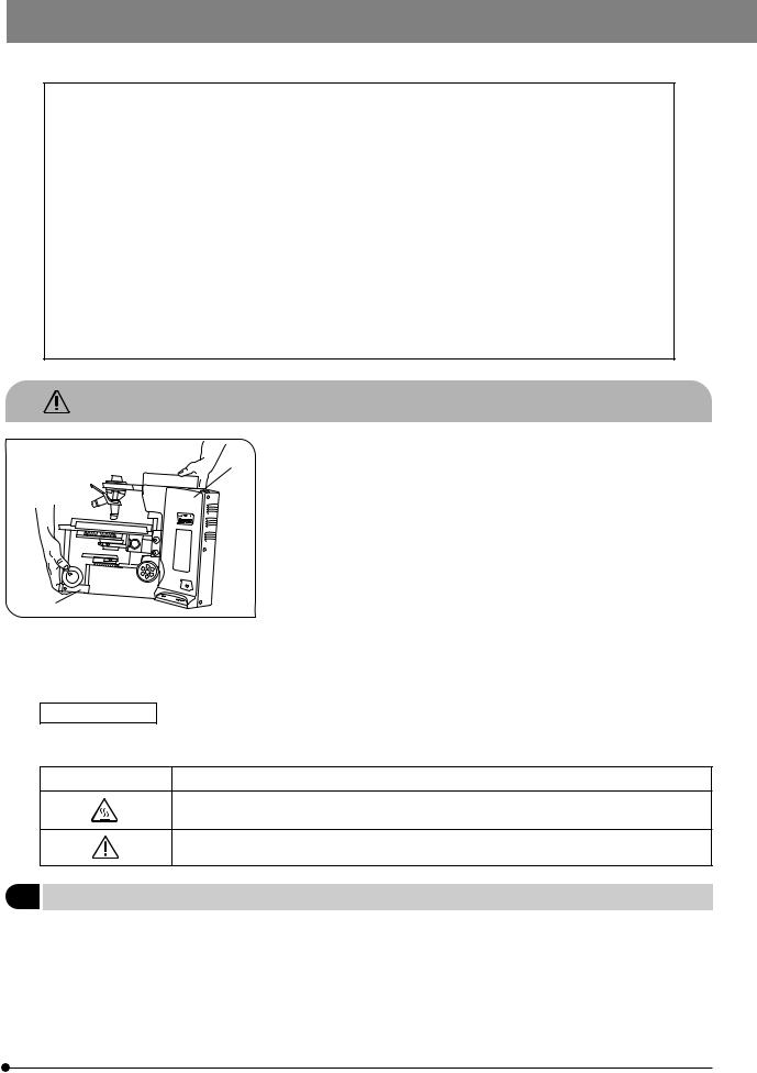
Fig. 1
Safety Symbols
1.After the equipment has been used in an observation of a specimen
²that is accompanied with a potential of infection, clean the parts coming in contact with the specimen to prevent infection.
·Moving this product is accompanied with the risk of dropping the specimen. Be sure to remove the specimen before moving this product.
·In case the specimen is damaged by erroneous operation, promptly take the infection prevention measures.
2.Culture liquid or water spilt on the stage, condenser or microscope may damage the equipment. Immediately wipe the liquid or water off if it is spilt on them.
3.When moving the microscope, disconnect the reflected light illuminator, observation tube and transmitted light lamp housing and carefully carry the microscope by the base (front edge) @ and the grasping part on the rear of the arm ² as shown in Fig. 1. (Weight: approx. 15 kg.)
Also be careful against slipping of hands during carrying.
#Damage to the microscope will occur if you grasp it by other parts including the stage, coarse/fine adjustment knob, etc.
The following symbols are found on the microscope. Study the meaning of the symbols and always use the equipment in the safest possible manner.
Symbol |
Explanation |
|
|
Indicates that the surface becomes hot, and should not be touched with bare hands.
Before use, carefully read the instruction manual. Improper use could result in personal injury to the user and/or damage to the equipment.
1 Getting Ready
1. A microscope is a precision instrument. Handle it with care and avoid subjecting it to sudden or severe impact. 2. The U-SWTR-3 super-widefield observation tube (FN 26.5) cannot be used with the BX51WI microscope.
3. The BX51WI microscope can be used with an intermediate attachment (such as a BX-URA2 or BX-RFA reflected light illuminator, U-ECA or U-CA magnification changer, etc.).
Two intermediate attachments can be used only in the following conditions:
· The U-CA or U-ECA magnification changer or U-FWO filter wheel can be mounted as the second attachment. · When a TV adapter with 1X or higher power is used, 2/3-inch CCD TV observation is possible.
· The peripheral areas of the field of view may be obscured or cut off in binocular observation using the U-TR30-2, U-ETR
or U-TR30IR (FN 22) super-widefield observation tube.
1

4.In IR (infrared) observation, the U-CA or U-ECA magnification changer can be used only when the U-ETR3 or U-TR30IR observation is used.
5.In photomicrography with visible light, correct exposure may be impossible if the microscope is set for IR observation. Be sure to engage the provided IR cut filter (light blue) before photomicrography.
6.When the XLUMPlanFl20XW objective is used, only the U-TV1X-2, U-TVCAC, U-PMTVC2XIR or U-PMTVC4XIR TV adapter can be used.
7.Do not attempt to remove or loosen the click springs and screws. Otherwise, Olympus can no longer warrant the performance of the microscope.
The clicking force of the revolving nosepiece has been set weak in order to reduce vibrations during objective switching. To reproduce the correct click position, switch the objectives gently by operating the lever.
8.Caution for use of the U-ETR3 upright trinocular tube:
When the aperture stop of the condenser is reduced using a reflected light fluorescence illuminator and the LUMPlanFl60XW objective, part of the observed field of view may be obscured slightly. This is due to the reduction of the light intensity in the field of view due to the narrow aperture and is not due to a defective optical adjustment of the microscope.
This phenomenon does not affect the photomicrography or TV camera light path.
2Maintenance and Storage
1.To clean the lenses and other glass components, simply blow dirty away using a commercially available blower and wipe gently using a piece of cleaning paper (or clean gauze).
If a lens is stained with fingerprints or oil smudges, wipe it gauze slightly moistened with commercially available absolute
alcohol.
 Since the absolute alcohol is highly flammable, it must be handled carefully.
Be sure to keep it away from open flames or potential sources of electrical sparks –– for example, electrical equipment that is being switched on or off.
Also remember to always use it only in a well-ventilated room.
2.Do not attempt to use organic solvents to clean the microscope components other than the glass components. To clean them, use a lint-free, soft cloth slightly moistened with a diluted neutral detergent.
3.Never attempt to disassemble any part of the microscope.
4.When not using the microscope, make sure to set the main switch to “ ” (OFF), confirm that the lamp housing is cool enough and cover the microscope with the provided dust cover.
5.When disposing of this unit, check the regulations and rules of your local government and be sure to observe them.
3Warning Indication
A warning sticker is attached to a part where special precaution is required when handling and using the system. Always heed the warning.
Warning indication |
Lamp housing (U-LH100-3/U-LH100IR) |
||
position |
(Warning against high temperature) |
|
|
|
|||
|
|
|
|
4Caution
If the microscope is used in a manner not specified by this manual, the safety of the user may be imperiled. In addition, the equipment may also be damaged. Always use the equipment as outlined in this instruction manual.
The following symbols are used to set off text in this instruction manual.
 : Indicates that failure to follow the instructions in the warning could result in bodily harm to the user and/or damage to equipment (including objects in the vicinity of the equipment).
# : Indicates that failure to follow the instructions could result in damage to equipment. } : Indicates commentary (for ease of operation and maintenance).
5Intended use
This instrument has been designed to be used to observe magnified images of specimens in routine and research applications.
Do not use this instrument for any purpose other than its intended use.
2
BX51WI
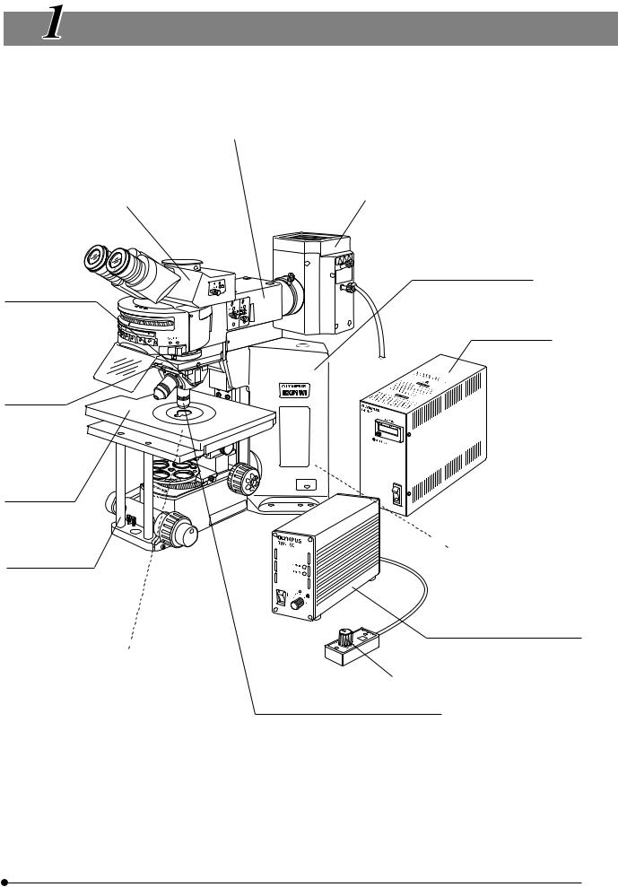
MODULE NOMENCLATURE
}The modules shown below are only the representative modules. As there are other modules which can be combined with the microscope but are not shown below, please also refer to the latest Olympus catalogues or your dealer.
Trinocular Observation Tube
·U-TR30-2 (FN 22)
·U-TR30IR (FN 22)
·U-ETR3 (FN 22)
Revolving Nosepiece
· WI-SRE3
· WI-SNPXLU2 · U-SLRE
Revolving Arm
WI-NPA
Cross Stage IX-SVL2
or commercially available bridge stage
Fixed-Stage Adapter
WI-FSH
Condenser 
·WI-UCD
·WI-DICD
·WI-OBCD
·U-UCD8
·U-SC3
·U-AAC
·U-AC2
Transmitted Arm BX-ARM
or Reflected Light Fluorescence Illuminator
·BX-URA2
·BX-RFA
Reflected Light Mercury Lamp Housing · U-LH100HG
· U-LH100HGAPO
Microscope Frame BX51WIF
Power Supply Unit
U-RFL-T


 Transmitted Light Lamp Housing
· U-LH100-3
· U-LH100IR
Power Supply Unit (for Halogen Bulb)
TH4
Hand Switch TH4-HS
Objective
·MPLN5X
·UMPlanFLN10XW/20XW
·LUMPlanFLN40XW/60XW
·LUMFLN60XW
·LUMPlanFl100XW
·XLUMPlanFI20XW
(exclusively for use with the WI-SNPXLU2)
·XLFluor2X/340
(exclusively for use with the U-SLRE)
·XLFluor4X/340
(exclusively for use with the U-SLRE)
3

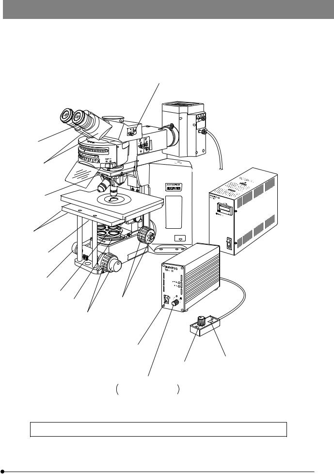
 CONTROLS
}If you have not yet assembled the microscope, read Chapter 9, “ASSEMBLY” (pages 36 to 42).
Interpupillary distance scale (Page 14)
Diopter adjustment ring (Page 14)
Reflected light  fluorescence illuminator
  (See the separately
provided instruction manual.)
Stage center plate
Y-axis knob (Page 12) 

X-axis knob (Page 12) 

Rubber cap for fine adjustment knob (Page 11)
Centering knob
(Accommodation position)
Pre-focusing lever (Page 11)
Coarse adjustment knob (Page 11)
Light path selector knob (Page 15)
Reflected light mercury lamp housing
(See the separately provided instruction manual.)
Power supply unit
(See the separately provided instruction manual.)
Power supply unit (See the separately provided instruction manual.)
Coarse adjustment knob (Page 11)
Coarse adjustment knob rotation tension adjustment ring (Page 11)
Fine adjustment knob (Page 11)
}The descriptions on the filter turret, revolving nosepiece, condenser, etc. will be given in the subsequent pages.
4
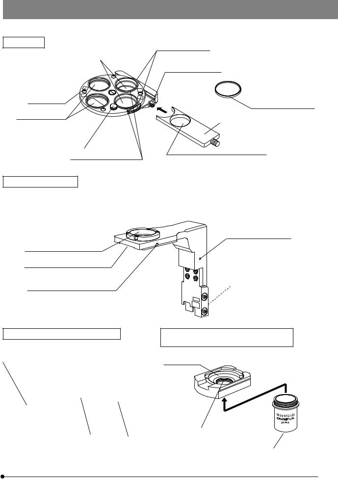
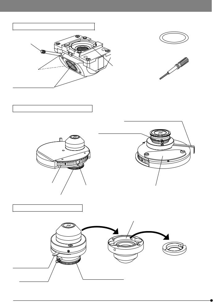
Filter Turret
Polarizer positions (Page 19)*
Accepts the 32PO or 32POIR.
Indication label attaching frame
Filter positions
Accepts 32 mm filters with thickness of no more than 6 mm.
Polarizer clamping knob (Page 19)
Polarizer push ring (Page 10)
Made of white plastic
BX51WI
Polarizer rotating dials (Page 23)
Slider insertion/removal stopper (Page 10)
*Accepts the combination of a polarizer push ring and a 32 mm filter. The thickness should be no more than 6 mm.
Filter frame reinforcing ring (Page 38)
Filter slider (Page 10)
IR filter insertion position Accepts the 32BP775, 32IR900 or a 32 mm filter with thickness of no more than 5.3 mm.
Revolving Arm WI-NPA
#Note that the revolving arm can be mounted only before the reflected light illuminator is mounted or before the transmitted light arm and IX-SVL2 stage are mounted (page 38).
}This revolving arm accepts the U-SLRE, WI-SNPXLU2 or WI-SRE3 revolving nosepiece.
Grounding screw hole (M3)
Light shield tube retaining screw
Revolving nosepiece mount dovetail
Microscope frame mount dovetail
Revolving nosepiece clamping screw
Sliding Revolving Nosepiece U-SLRE
Switching lever
Single-Position Revolving Nosepiece XLU
WI-SNPXLU2
DIC mount hole (Page 20)
|
|
UIS2 (UIS) objective |
|
|
XLU objective mount screw |
|
||
XLFluor objective mount screw |
|
|
|
M 25 mm, pitch 0.75 mm |
||||
|
mount screw |
|
|
|||||
M 34 mm, pitch 1 mm |
|
|
|
UIS2 (UIS) objective mount screw |
||||
|
|
|
||||||
|
|
|
|
|||||
|
|
|
|
|
|
|
|
|
|
|
|
|
|
|
|
|
|
|
|
|
|
|
|
RMS Adapter WI-RMSAD |
||
|
|
|
|
|
|
|
|
|
5
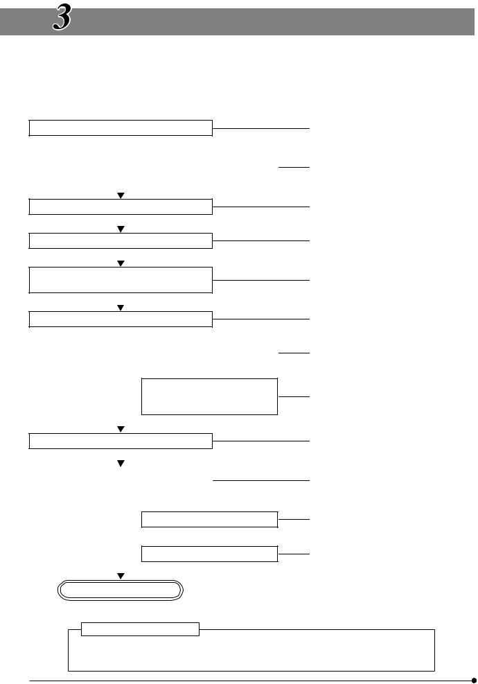
Swinging Revolving Nosepiece WI-SRE3
Swing lever
Centering screw
UIS2 (UIS) objective mount screws
Confocality correction washers (Kinds of thickness: 10, 30 and 50 μm; three washers per kind)
DIC mount hole (Page 20)
Centering knob
Long-WD Universal Condenser WI-UCD
Aperture iris diaphragm lever (Page 17)
Quarter-wave plate clamping knob
Turret (4 positions) |
|
Optical element index |
|
|
|
mount (Page 21) |
|
DIC prism replacement cover |
|
|
|
|
||
Quarter-wave plate rotation |
|
|
|
|
|
|
|
|
|
ring (Page 23) |
|
|
|
|
|
|
|
|
|
Long-WD DIC Condenser WI-DICD
DIC prism (large) mount position
Aperture iris diaphragm |
DIC prism (small) adapter |
lever (Page 17) |
|
Quarter-wave plate
Quarter-wave plate rotation
clamping knob
ring (Page 23)
6
BX51WI
Differential Interference Contrast Prisms (For Condenser)
}The WI-UCD condenser accepts two large and two small DIC prisms while the WI-DICD condenser accepts one large or small DIC prism.
When selecting the brightfield (BF) light path using the WI-UCD, leave one DIC prism (large) mount position empty.
Positioning indices
· WI-DIC10HR |
· WI-DIC40HR |
|
· WI-DIC60HR |
||
· WI-DIC20HR |
||
· U-LDPXLU20HR |
||
|
||
Index |
Index |
Long-WD Oblique Condenser WI-OBCD
Aperture iris diaphragm lever (Page 17)
Oblique iris insertion/removal knob (Page 17)
High-Resolution DIC Prism A |
WI-DICTHRA2 |
DIC Prism |
WI-DICT2 |
}This prism can be mounted in the DIC prism position of the WI-SNPXLU2 or WI-SRE3.
Applicable condensers
WI-DICTHRA2: WI-UCD, WI-DICD
WI-DICT2: U-UCD8
Positioning pin
 Condensers and Applicable Objective Magnifications
Condenser |
Applicable Objective Magnification |
|
WI-UCD |
|
|
WI-DICD |
5X or more |
|
WI-OBCD |
|
|
|
|
|
U-UCD8 |
2X or more |
|
U-SC3 |
||
|
||
|
|
|
U-AAC |
10X or more |
|
|
|
|
U-AC2 |
5X or more |
|
|
|
7
TRANSMITTED LIGHT BRIGHTFIELD
OBSERVATION PROCEDURE
}The following flow shows the operating procedure for the transmitted light brightfield observation which is the basic observation method of this microscope. The operating procedures for DIC observation, fluorescence DIC observation and IR DIC observation will be described separately in Chapter 5, “OTHER OBSERVATION METHODS” on page 19.
|
|
|
|
|
(Controls Used) |
(Page) |
|
Set the main switch to “ I ” (ON). |
@Main switch |
(P. 10) |
|||||
²Lamp ON-OFF switch |
(P. 10) |
||||||
|
|
|
|
|
|||
|
|
|
|
|
|||
|
|
|
|
|
(Only when the hand switch is used) |
|
|
|
|
|
|
|
|
|
|
|
|
|
Disengage the filter from the light |
³Filter turret |
(P. 10) |
||
|
|
|
path. |
||||
|
|
|
|
|
|||
|
|
|
|
|
|Light path selector knob |
(P. 15) |
|
|
|
|
|
|
|||
Select the binocular light path. |
|||||||
|
|
|
|
|
ƒX-axis and Y-axis knobs |
(P. 12) |
|
|
|
|
|
|
|||
Place the specimen on the stage. |
|||||||
|
|
|
|
|
|
|
|
|
|
|
|
|
|
|
|
Engage a low-magnification objective in the |
…Swing lever |
(P. 13) |
|||||
light path. |
|||||||
|
|
||||||
|
|
|
†Coarse/fine adjustment knobs |
(P. 11) |
|||
|
|
|
|
|
|||
Bring the specimen in focus. |
|||||||
|
|
|
|
|
|
|
|
|
|
|
|
|
|
||
|
|
|
Adjust the brightness. |
‡Light intensity control knob |
(P. 10) |
||
|
|
|
|||||
|
|
|
|
|
ŠBinocular tube |
(P. 14) |
|
|
|
|
Adjust the interpupillary distance. |
||||
|
|
|
‰Diopter adjustment ring |
(P. 14) |
|||
|
|
|
Adjust the diopter. |
||||
|
|
|
‹Condenser height adjustment knob |
(P. 16) |
|||
|
|
|
Adjust the light axis. |
||||
|
|
|
ŒCondenser centering knob |
(P. 16) |
|||
|
|
|
|
|
|||
|
|
|
|
|
™Aperture iris diaphragm lever |
(P. 17) |
|
Adjust the aperture iris and field iris diaphragms. |
|||||||
šField iris diaphragm ring |
(P. 16) |
||||||
|
|
|
|
|
|||
|
|
|
|
|
|||
|
|
|
|
|
|||
|
|
|
|
|
|
|
|
Engage the objective to be used in the light |
|
…Swing lever |
(P. 13) |
||||
path and bring the specimen in focus. |
|
†Coarse/fine adjustment knobs |
(P. 11) |
||||
|
|
|
|
|
|
|
|
|
|
|
Engage the required filters. |
³Filter turret |
(P. 10) |
||
|
|
|
|||||
|
|
|
Adjust the brightness. |
‡Light intensity control knob |
(P. 10) |
||
|
|
|
|||||
|
|
|
|
|
|
|
|
Start observation.
Tip for microscope operation
In patch-clamp testing, switch the microscope controls cautiously and gently so that the patch electrodes do not slip off.
8
BX51WI
|
‰
Š
…
ƒ
‹Œ™
†
³
š †
†
@
²
‡
‡
Used only when the hand switch is not connected
} Make a photocopy of the observation procedure pages and post it near your microscope.
9
USING THE CONTROLS
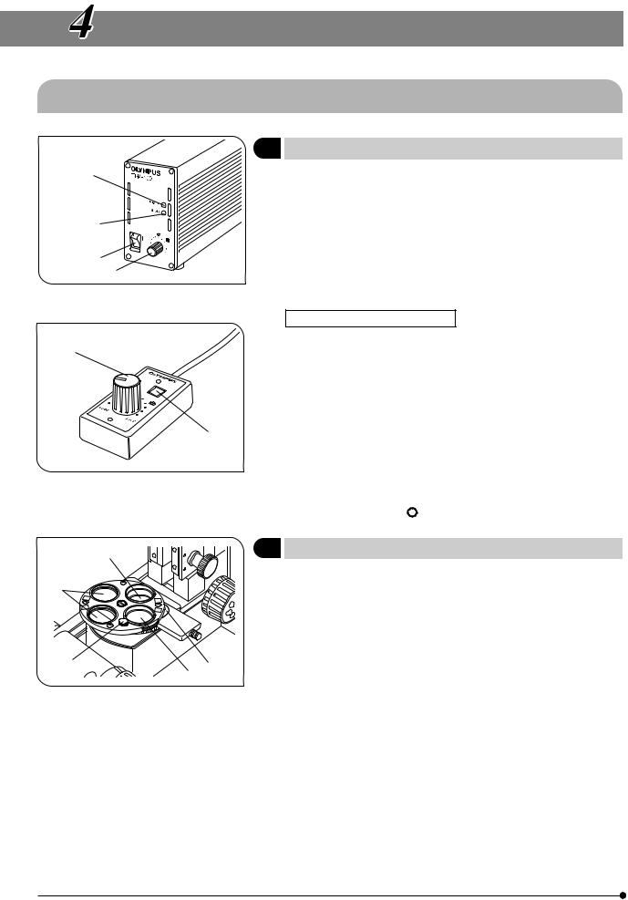
4-1 Microscope Base, Power Supply Unit (TH4)
1 |
Controlling the Light Intensity (TH4) |
(Figs. 2 & 3) |
|||
³ |
}See the separately provided instruction manual for details. |
||||
|
1. |
Make sure that the light intensity control knob @ is set to MIN (minimum |
|||
|
|
voltage), then set the main switch ² to “ I ” (ON). (The POWER LED ³ |
|||
| |
|
should light up.) |
|
||
2. |
Turn the knob @ clockwise toward MAX (maximum voltage) to increase |
||||
|
|||||
² |
|
the intensity and brightness. |
|
||
}The |
marking indicates the position where the optimum daylight for |
||||
@ |
|
color photography is obtained when the LBD filter is engaged in the light |
|||
|
|
||||
Fig. 2 |
|
path. |
|
|
|
|
|
|
|
||
|
Operation Using the Hand Switch |
|
|||
ƒ |
}When the hand switch is connected (when the REMOTE LED | is lit), the |
||||
|
light intensity control knob @ is defeated and only the light intensity |
||||
|
|
control knob ƒ of the hand switch can be used. |
|
||
|
|
The hand switch is provided with double-side adhesive tape so that it |
|||
|
|
can be attached onto a convenient position for operation. |
|||
|
1. |
After setting the main switch ² to “ I ” (ON), press the lamp ON-OFF switch |
|||
|
|
… to ON and adjust the brightness with the intensity control knob ƒ. |
|||
…2. To turn the lamp OFF, press the lap ON/OFF switch … again to OFF.
#The lighting of the REMOTE LED | indicates that the hand switch is standing by. The hand switch consumes a power of about 2.5 W
Fig. 3 |
when it stands by. |
|
When the system is not to be used for a lone period, be sure to set |
|
the main switch ² to “ ” (OFF). |
@ |
2 |
Using the Filter Turret |
(Fig. 4) |
|
|
|
|
|
|
³ |
|
}Filters with a diameter of 32 mm can be inserted in positions @ to |. |
||
|
1. |
Filter positions @ and ² are rotatable. When the 32PO polarizer or 32POIR |
||
|
|
|
polarizer is placed in either position, the polarizer or filter can be fixed by |
|
|
|
|
using the push ring (made of white plastic). |
|
|
|
}When filter position @ is engaged in the light path, the rotation fixing |
||
|
|
|
knob ƒ comes at the front where the operation is easy. |
|
ƒ |
| |
2. |
Filter position ³ accepts any type of 32 mm filter. |
|
² |
#When using two filters together, the thickness of the lower filter should |
|||
Fig. 4 |
|
|
be no more than 2 mm. Otherwise, the upper filter may drop during |
|
|
|
rotation. |
|
|
|
|
|
|
|
|
|
3. |
Filter position | accepts the 32BP775 or 32IR900 filter. As the filter can- |
|
|
|
|
not be inserted unless the filter slider is removed, remove it by releasing |
|
|
|
|
the insertion/removal stopper below the slider and loosening the slider |
|
|
|
|
clamping screw using the provided Allen screwdriver. |
|
10
BX51WI
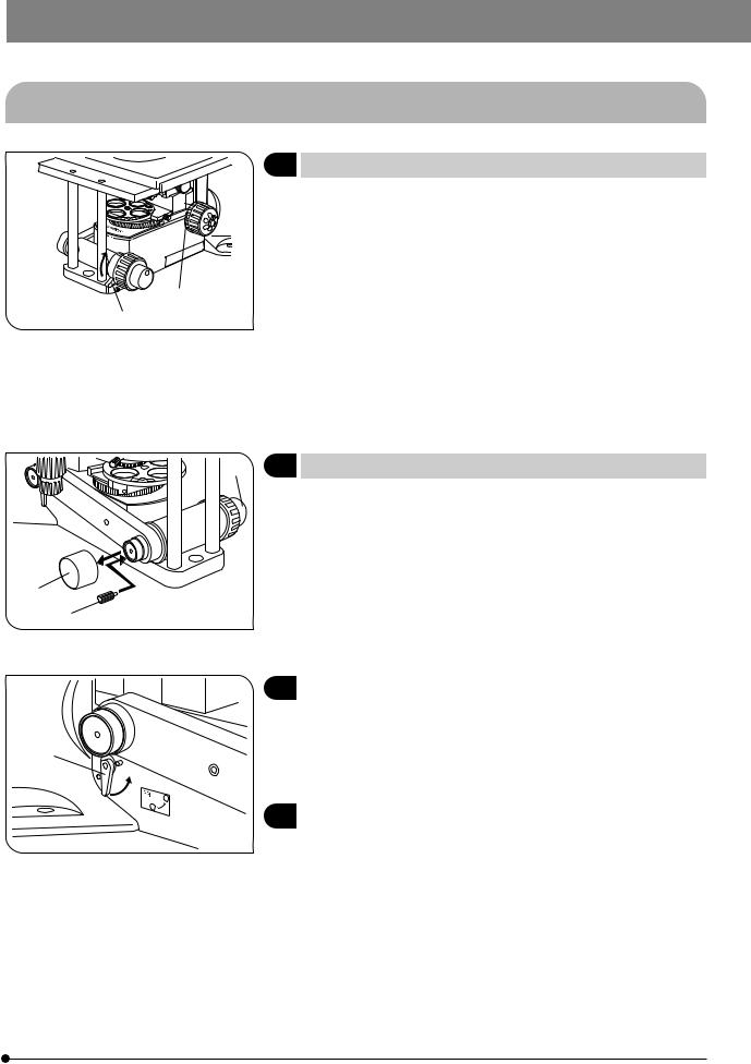
4-2 Focusing Block
@
Fig. 5
1 |
Using the Pre-focusing Lever |
(Fig. 5) |
|
|
}The pre-focusing lever prevents collision between the specimen and |
||
|
objective and simplifies the focusing operation. After bringing the |
||
|
specimen into approximate focus with the coarse adjustment knob, turn |
||
|
the pre-focusing lever @ in the direction of the arrow to lock it. Hereafter, |
||
|
the lower limit of the coarse adjustment will be limited at the position |
||
² |
where the lever is locked. When bringing a specimen in focus, approximate |
||
focus can be obtained by simply lowering the coarse adjustment to the |
|||
|
|||
|
stopper position so all you have to do more is control the fine adjustment |
||
|
knob. |
|
|
|
}The up/down movement using the fine adjustment knob is not limited. |
||
|
#When the pre-focusing lever is locked, the coarse adjustment stroke |
||
|
is limited by the mechanism and it cannot reach the previous upper |
||
|
limit. If you want to control the coarse adjustment knob to the previous |
||
|
upper limit, unlock the pre-focusing lever. |
|
|
@
²
Fig. 6
@
Fig. 7
³2 Using the Fine Adjustment Fast-Feed Knob (Fig. 6)
}Fine focusing is usually possible while the rubber cap @ is attached. However, when it is desirable to allow the fine adjustment knob to vary focusing by a large amount, though this is not be as large as with the coarse adjustment knob, the rubber cap can be removed and the provided fine adjustment fast-feed knob attached in place.
}If you remove the knob by loosening the screw clamping the fine adjustment knob ³ from the opposite side, the fine adjustment can be controlled using the tip or thick of your finger.
3 |
Using the Frost Switching Lever |
(Fig. 7) |
}Low observation light can be brightened by turning the frost switching lever @ which controls the built-in frost filter, in the direction of the arrow. However, although the brightness is increased, irregularity in lighting may also increase.
4 |
Adjusting the Coarse Adjustment Knob Rotation Tension (Fig. 5) |
#Do not adjust the coarse adjustment knob rotation tension adjustment ring (² in Fig. 5) because the belt interlocking of the ring with the coarse adjustment knob on the front has been adjusted at the factory. If the tension is varied, the accuracy of the pre-focusing lever will deteriorate.
11
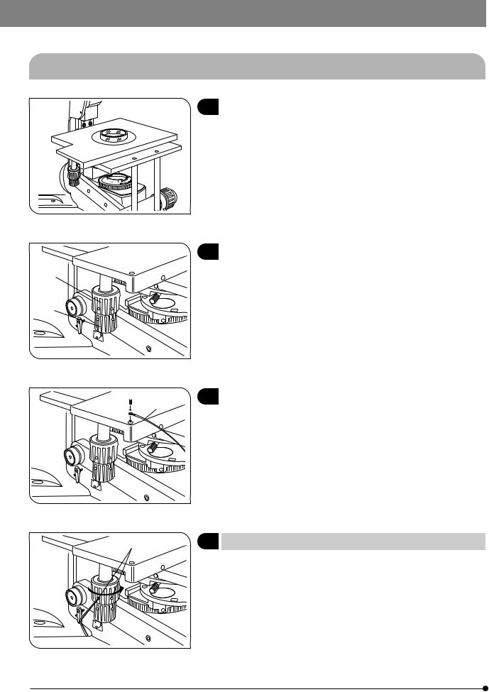
4-3 Stage (IX-SVL2)
Fig. 8
²
@
Fig. 9
 ²
²
@
Fig. 10
@
Fig. 11
1 |
Placing the Specimen |
(Fig. 8) |
1. Place the specimen on the center of the stage.
}The optional stage center plate (IX-CP50) makes it possible to observe a wide range of a big petri dish, etc. (Central hole diameter: 50 mm)
2 |
Moving the Specimen |
(Fig. 9) |
1.The specimen can be moved by turning the X-axis knob @ and Y-axis knob ².
The movement strokes are 50 mm (X-axis) x 43 mm (Y-axis).
3 |
Setting the Grounding |
(Fig. 10) |
}In case of electrical physiological experiment, etc., the specimen can be grounded from the stage.
Prepare a grounding wire @ and M4 screw ² and attach grounding as shown in Fig. 10.
#The screw hole may sometimes be stuck by paint, etc. In such a case, screw in the M4 screw a few times to expose the metallic thread inside the screw hole and improve the contact before attaching the grounding wire firmly.
4 Adjusting the X-Axis/Y-Axis Knob Rotation Tension (Fig. 11)
}The rotation tension of the X-axis and Y-axis knobs can be adjusted independently.
1.Loosen the 2 set screws @ of a knob using the provided Allen wrench, hold the stage so that it will not move, then turn the knob to adjust the tension. Turning it in the direction of the arrow increases the tension and turning in the opposite direction decreases the tension.
2.After adjustment, tighten the set screws firmly.
#If the tension of a knob is too heavy or too light, skipping or returning of image may occur during the stage movement.
12
 Loading...