


INSTRUCTIONS
BX43
SYSTEM MICROSCOPE
This instruction manual is for the Olympus System Microscope Model BX43.
To ensure the safety, obtain optimum performance and to familiarize yourself fully with the use of this microscope, we recommend that you study this manual thoroughly before operating the microscope.
Retain this instruction manual in an easily accessible place near the work desk for future reference.
A X 7 8 5 1

In accordance with European Directive 2002/96/EC on Waste Electrical and Electronic Equipment, this symbol indicates that the product must not be disposed of as unsorted municipal waste, but should be collected separately.
Refer to your local Olympus distributor in EU for return and/or collection systems available in your country.
NOTE: This equipment has been tested and found to comply with the limits for a Class A digital device, pursuant to Part 15 of the FCC Rules. These limits are designed to provide reasonable protection against harmful interference when the equipment is operated in a commercial environment. This equipment generates, uses, and can radiate radio frequency energy and, if not installed and used in accordance with the instruction manual, may cause harmful interference to radio communications. Operation of this equipment in a residential area is likely to cause harmful interference in which case the user will be required to correct the interference at his own expense.
FCC WARNING: Changes or modifications not expressly approved by the party responsible for compliance could void the user's authority to operate the equipment.

BX43
CONTENTS
Correct assembly and adjustments are critical for the microscope to exhibit its full performance. If you are going to assemble the microscope yourself, please read section 10, “ASSEMBLY” (pages 33 to 37) carefully.
--IMPORTANT -- Be sure to read this section for safe use of the equipment. |
1-3 |
||||||
|
|
|
|
|
|
||
|
|
|
|
|
|
||
1 |
MODULE NOMENCLATURE |
|
|
|
4 |
||
|
|
|
|
|
|
||
2 |
CONTROLS |
|
|
|
5-7 |
||
|
|
|
|
|
|
||
3 |
FLOW OF OBSERVATION |
|
|
|
8,9 |
||
|
|
|
|||||
4 |
SIMPLIFIED OBSERVATION PROCEDURE |
10-12 |
|||||
|
4-1 |
Basic Operation (Until Observation of Specimen)...................................................................... |
10,11 |
||||
|
4-2 |
Microscope Adjustments (How to improve the Observed image)..................... |
11,12 |
||||
|
|
1 |
Adjusting the Interpupillary |
|
2 Adjusting the Left and Right |
|
|
|
|
|
Distance................................................................................ |
11 |
|
Focusing............................................................................... |
11 |
|
|
3 |
Adjusting the Centering................................. |
12 |
4 |
Adjusting the Contrast..................................... |
12 |
|
|
|
|
|
|
||
5 |
USING THE CONTROLS |
|
|
|
13-25 |
||
|
5-1 |
Base.............................................................................................................................................................................................................. |
|
|
|
13-15 |
|
|
|
1 |
Adjusting the Brightness............................... |
13 |
2 |
Setting the LIM Brightness......................... |
13 |
|
|
3 |
Using the Filters (Halogen Bulb |
|
|
|
|
|
|
|
Operation Only).......................................................... |
14 |
|
|
|
|
5-2 |
Focusing Block................................................................................................................................................................................ |
|
|
|
16,17 |
|
|
|
1 |
Focusing Controls.................................................. |
16 |
2 |
Adjusting the Focus............................................. |
16 |
|
|
3 |
Replacing the Fine Adjustment |
|
4 |
Adjusting the Coarse Adjustment |
|
|
|
|
Knob............................................................................................ |
17 |
|
Knob Tension................................................................. |
17 |
|
|
5 |
Pre-focusing Lever.................................................. |
17 |
|
|
|
|
5-3 |
Stage............................................................................................................................................................................................................ |
|
|
|
18-24 |
|
|
|
1 |
Placing the Specimen....................................... |
18 |
2 |
Using the Auxiliary Slide Holder.........18 |
|
|
|
3 |
Adjusting the X- and Y-Axis |
19 |
4 |
Rotating the Stage............................................... |
20 |
|
|
|
Knob Tension................................................................ |
|
|
|
|
|
|
5 |
Adjusting the Stage Height..................... |
20 |
|
|
|
|
5-4 |
Observation Tube................................................................................................................................................................... |
|
|
|
21-24 |
|
|
|
1 |
Adjusting the Diopter....................................... |
21 |
2 |
Using the Eye Shades.................................... |
21 |
|
|
3 |
Using the Eyepiece Micrometer |
|
4 |
Selecting the Light Path of the |
|
|
|
|
Disk............................................................................................ |
22 |
|
Trinocular Tube........................................................ |
22 |
|
|
5 |
Adjusting the Tilt..................................................... |
23 |
6 |
Using Eyepieces Incorporating a |
|
|
|
|
|
|
|
Micrometer...................................................................... |
24 |
|
5-5 Condenser................................................................................................................................................................................................... |
|
|
|
24 |
||
1 Compatibility of Objectives and |
|
Condensers................................................................... |
24 |

|
|
|
5-6 |
.................................................................................................................................................................Immersion Objectives |
25 |
|
1 Using Immersion Objectives................. |
25 |
5-7 |
Objectives with Correction Collar.............................................................................................................................. |
25 |
6 CAMERA RECORDING |
|
26 |
1 System Chart.......................................................... |
26 2 Selecting the Camera Adapter |
26 |
|
Magnification......................................................... |
7TROUBLESHOOTING GUIDE
8SPECIFICATIONS
27-29
30,31
9 |
OPTICAL CHARACTERISTICS (UIS2 Series) |
32 |
10 |
ASSEMBLY -- See this section for the replacement of the light bulb. -- |
33-37 |
11 |
HALOGEN LAMP SOCKET INSPECTION SHEET |
38 |
|
PROPER SELECTION OF THE POWER SUPPLY CORD.......................................................... |
39,40 |
BX43
IMPORTANT
SAFETY PRECAUTIONS |
(Fig. 1) |
1.After the equipment has been used in an observation of a specimen that is accompanied with a potential of infection, clean the parts coming in contact with the specimen to prevent infection.
·Moving this product is accompanied with the risk of dropping the specimen. Be sure to remove the specimen before moving this product.
·In case the specimen is damaged by erroneous operation, promptly take the infection prevention measures.
·Follow the procedures described in Chapter “Getting Ready” (see on page 2) prior to using the accessories of this product. Otherwise, the stability of the device will be lost and the dropped specimen will cause the possibility of infection.
2.Install the microscope on a sturdy, level table or bench.
3.Be careful not to tilt the microscope too much. Otherwise, the mobile parts such as the light path selector knob may move in unintended directions.
4.Always use the power cord provided by Olympus. If no power cord is provided, please select the proper power cord by referring to the section “PROPER SELECTION OF THE POWER SUPPLY CORD” at the end of this instruction manual.
If the proper power cord is not used, product safety performance cannot be warranted.
5.Always ensure that the grounding terminal of the microscope and that of the wall outlet are properly connected. If the equipment is not grounded, Olympus can no longer warrant the electrical safety performance of the equipment.
Operation Using the LED Lamp
 Safety Note on LED (Light Emitting Diode)
The LED incorporated in the LED lamp housing is a class 1 LED product as defined in the applicable standard. The light emitted by LED is basically safe, but do not look at the illumination light directly for an extended period to prevent your eye from being injured
CLASS 1 LED PRODUCT
Operation Using the Halogen Bulb
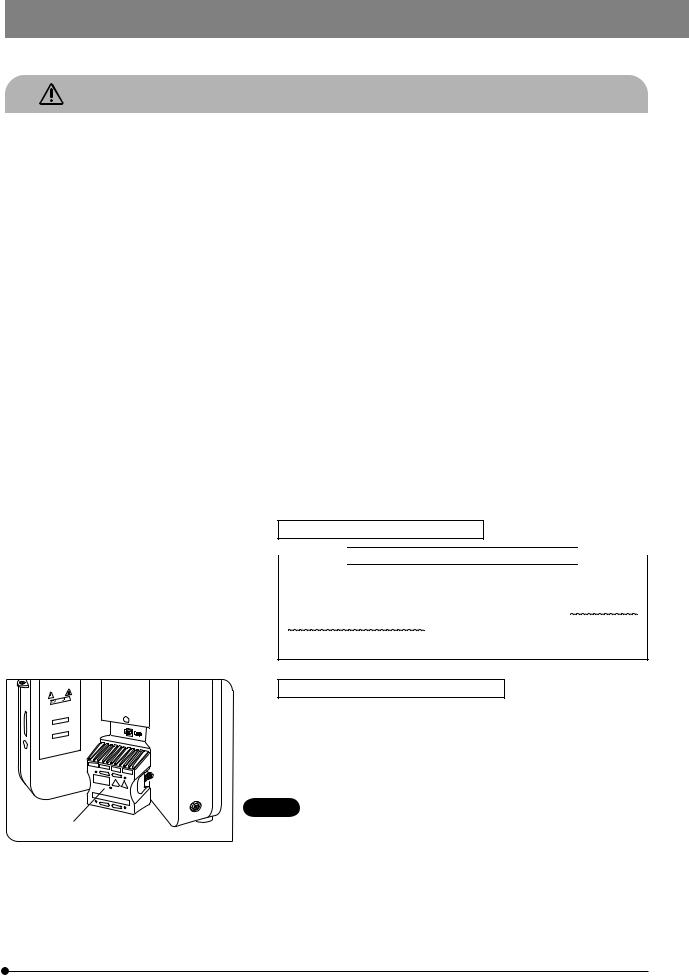
1. To avoid potential shock hazards and burns when replacing the halogen bulb, set the main switch of the TL4 power supply unit to “ ” (OFF) and allow the lamp socket @ and bulb to cool before touching them.
Designated bulb |
6V30WHAL (PHILIPS 5761) |
|
|
CAUTION Always use the designated lamp bulb. Using other bulb may
1
Fig. 1
cause malfunction.
2.If the lamp cable or power cord comes in contact with the lamp socket or its surroundings, the cable or cord may be melt by the heat, causing an electric shock or fire hazard. To prevent this, distribute the lamp cable and power cord at enough distances from the lamp socket.
3.The standard service life of the lamp housing is eight (8) years of use or 20,000 hours of total power ON period, whichever is the shorter period. For details, see Inspection Sheet on page 38.
1
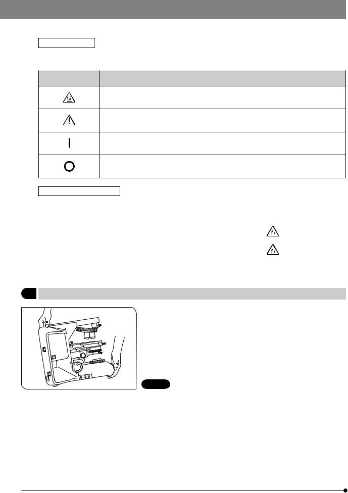
Safety Symbols
The following symbols are found on the microscope. Study the meaning of the symbols and always use the equipment in the safest possible manner.
Symbol |
Explanation |
Indicates that the surface becomes hot, and should not be touched with bare hands.
Indicates a non-specific general hazard. Follow the description given after this symbol or in instruction manual.
Indicates that the main switch is ON.
Indicates that the main switch is OFF.
Caution engraving/label
Caution engraving and label are placed at parts where special precaution is required when handling and using the microscope. Always heed the cautions.
Caution engraving |
Halogen lamp socket |
||
position |
[Caution against high temperature] |
|
|
|
|||
|
|
|
|
Caution label |
Rear panel |
||
position |
[Caution against high temperature] |
|
|
|
|||
|
|
|
|
If a caution engraving or label is dirty or peeled off, contact Olympus for the replacement or other inquiry.
1 Getting Ready
Fig. 2
1.A microscope is a precision instrument. Handle it with care and avoid subjecting it to sudden or severe impact. Also note that the microscope does not have a waterproof construction.
2.Do not use the microscope where it is subjected to direct sunlight, high temperature and humidity, dust or vibrations. (For the operating conditions, refer to section 8, “SPECIFICATIONS”.)
3.When moving the microscope, remove the observation and specimen and carefully carry the microscope by holding the grasping part on the rear of the arm and the front part of the base as shown in Fig. 2.
CAUTION To prevent damage to the microscope, never hold it by the stage or coarse/fine adjustment knob.
·Even when moving the microscope along the desktop surface, be sure to remove the specimen in advance.
·When the microscope needs to be packaged for forwarding to a remote location, contact Olympus.
4.When the accessories of this product are used, make sure that the system height does not exceed 1 meter. Otherwise, the stability of the device will be lost.
2

BX43
2 Maintenance and Storage
1.To clean the lenses and other glass components, simply blow dirt away using a commercially available blower and wipe gently using a piece of cleaning paper (or clean gauze).
If a lens is stained with fingerprints or oil smudges, wipe it gauze slightly moistened with commercially available absolute alcohol.
CAUTION · Since the absolute alcohol is highly flammable, it must be handled carefully.
Be sure to keep it away from open flames or potential sources of electrical sparks --- for example, electrical equipment that is being switched on or off, which could cause ignition of a fire.
Also remember to always use it only in a well-ventilated room.
·Set the main switch to “ ” (OFF) and wait for the lamp housing to cool down sufficiently before proceeding to maintenance.
2.Do not use organic solvents to clean the microscope components other than the glass components. To clean them, use a lint-free, soft cloth slightly moistened with a diluted neutral detergent.
3.Do not disassemble any part of the microscope except for the parts that are specified to be disassembled in this manual, as this could result in malfunction or reduced performance.
4.After using the microscope, set the main switch to “ ” (OFF), (wait for the lamp socket to cool down sufficiently if the halogen bulb has been used,) and keep it covered with a dust cover during storage.
5.Before disposing of this product, be sure to follow the regulations and rules of your local government.
3 Caution
If the microscope is used in a manner not specified by this manual, the safety of the user may be imperiled. In addition, the equipment may also be damaged. Always use the equipment as outlined in this instruction manual.
The following symbols are used to set off text in this instruction manual.
CAUTION : Indicates a potentially hazardous situation which, if not avoided, may result in minor or moderate injury or damage to the equipment or other property. It may also be used to alert against unsafe practices.
}: Indicates commentary (for ease of operation and maintenance).
4 Intended use
This instrument has been designed to be used to observe magnified images of specimens in various routine work and research applications.
Do not use this instrument for any purpose other than its intended use.
This instrument is considered a medical device in the following countries: US, and China.
This device complies with the requirements of directive 98/79/EC concerning in vitro diagnostic medical devices. CE marking means the conformity to the directive.
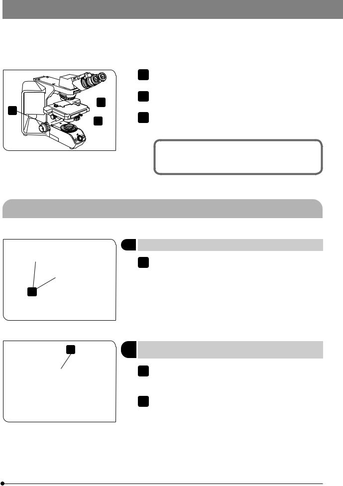
3
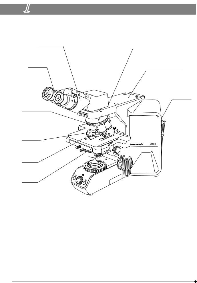
1 MODULE NOMENCLATURE
}The modules mentioned below show only the typical product names. As there are some products that are not mentioned but also applicable to this microscope, check the latest catalogues or consult Olympus.
For the products marked “ * ”, also read their instruction manuals.
Observation tube
·U-BI30-2
·U-TBI-3
·U-TR30-2
·U-TTLBI
Eyepieces
·WHN10X
·WHN10X-H
Revolving nosepiece
· BX43-5RES · U-5RE-2
· U-D6RE
Slide holder
· U-HLST-4
· U-HD-4
· U-HLDT-4
Stage
· U-SVRB-4 · U-SVRO
Condenser
· U-LC
· U-SC3
· U-AC2
Intermediate attachment
·U-TRA
·U-CA
·U-DO3
Arm (or vertical illuminator)
·BX3-ARM
·BX3-URA*
·BX3-RFAS*
Lamp housing
· U-LHLEDC · U-LS30-5
4
2 |
BX43 |
CONTROLS |
}If you have not yet assembled the microscope, read section 10, “ASSEMBLY” (pages 33 to 37).
Interpupillary distance adjustment scale (Page 22)
Diopter adjustment ring (Page 22)
Slide holder clamping lever (Page 19)
Aperture iris diaphragm ring (Page 12)
Condenser centering screws (Page 12) 


Filter mount (Page 15)
Field iris diaphragm ring (Page 12)
Coarse adjustment tension adjustment ring (Page 18)
Condenser height adjustment knob (Page 12)
Allen screwdriver holder
Coarse adjustment knob (Page 18)
Y-axis knob (Page 20)
X-axis knob (Page 20)
5

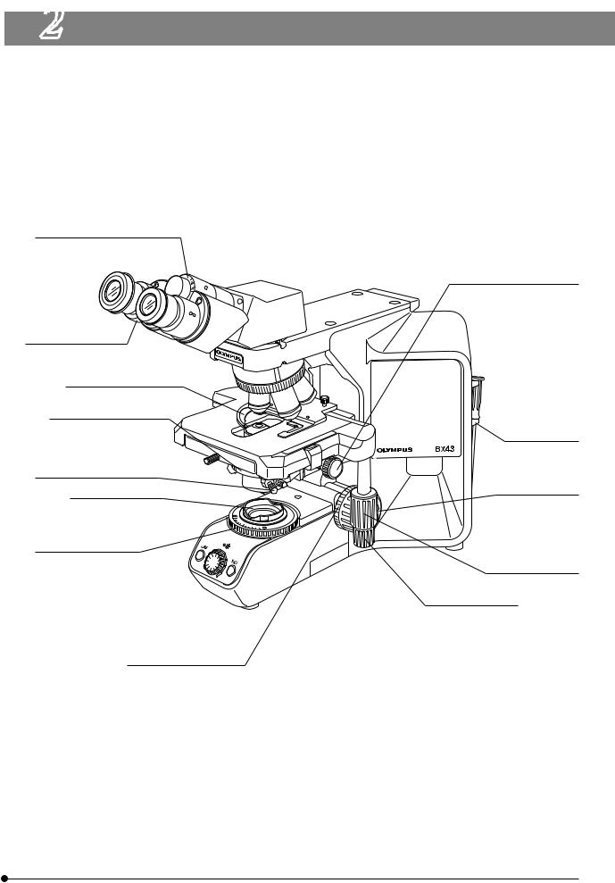
Main switch (Page 10) |
|
|
I : ON |
|
|
: OFF |
|
|
Pre-focusing lever |
|
|
(Page 16) |
|
|
Fine adjustment knob |
LIM setting switch |
|
(Page 13) |
||
(Page 16) |
||
|
||
|
LED brightness adjustment |
|
|
knob (Page 13) |
|
LIM indicator |
LIM ON-OFF switch |
|
|
||
ON: Lit (Green) |
(Page 13) |
|
OFF: Extinguished |
|
6
BX43
Low Magnification Condenser |
Swing-out Condenser |
U-LC |
U-SC3 |
Auxiliary lens mounting |
Top lens |
|
|
tool (for BX53) |
|
|
Top lens swing-out |
|
knob |
Aperture iris diaphragm ring (Page 12)
Auxiliary lens
Condenser mount dovetail
* The auxiliary lens is mounted on the lamp adapter when the U-LC is used. (Page 34)
<<Modules for halogen lamp operation>>
LS30 Adapter |
|
Halogen Lamp Socket |
U-LS30ADP |
|
U-LS30-5 |
Guide pins
Guide pin holes
Lamp cable
Power Supply Unit
TL4
Lamp socket connector
Brightness control knob
Main switch
I : ON  : OFF
: OFF
7
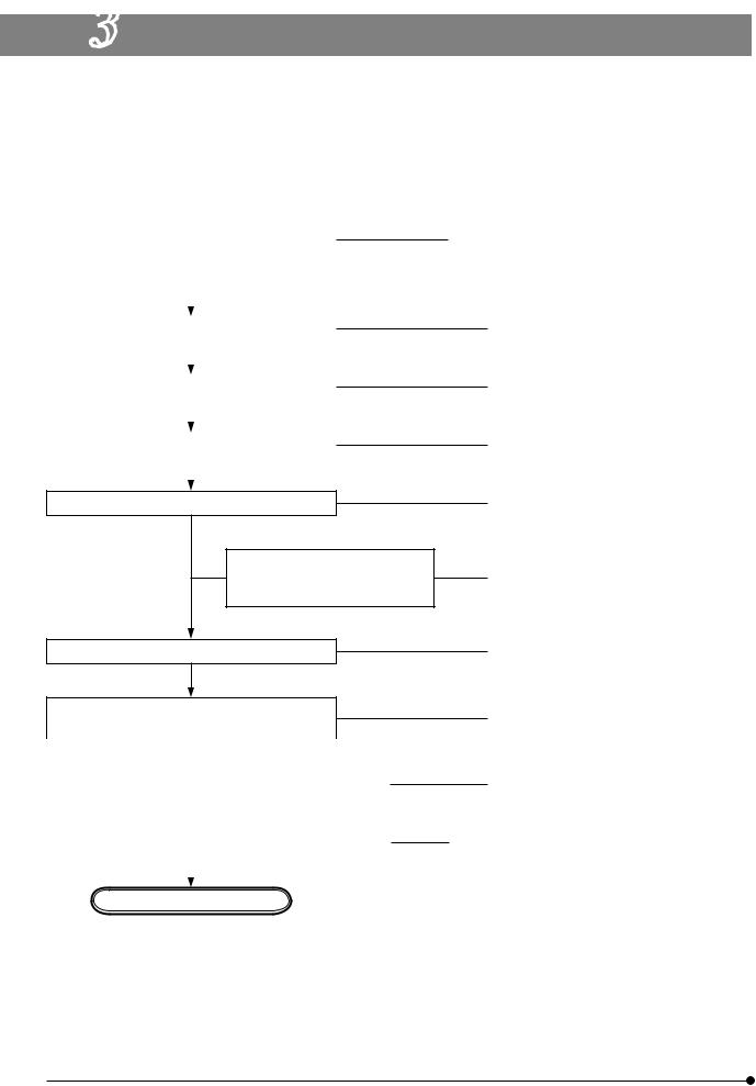
3 FLOW OF OBSERVATION
}When the LED lamp is used and the LIM is set, the LED brightness adjustment knob is defeated.
}When the halogen bulb is used, set the LBD filter in the filter mount on the base (or in the U-FC filter cassette).
|
|
|
(Controls Used) |
(Page) |
|||
|
|
|
|
|
|
|
|
|
|
|
LED lamp |
|
Halogen bulb |
|
|
|
|
@Main switch |
3Main switch |
|
|||
Set the main switch to “ I ” (ON) and adjust |
|
||||||
2LED brightness |
|Brightness |
(P. 13) |
|||||
the brightness. |
|||||||
|
adjustment knob* |
adjustment knob |
|
||||
|
|
|
|
||||
|
|
|
|
|
|
|
|
|
|
|
|
|
|
|
|
Select the light path (trinocular tube). |
|
5Light path selector knob |
(P. 22) |
||||
|
|
|
6Slide holder |
|
(P. 19) |
||
|
|
|
|
||||
|
|
|
|
||||
Place the specimen on the stage. |
|
||||||
|
7X-/Y-axis knobs |
(P. 20) |
|||||
|
|
|
|||||
|
|
|
|
|
|
|
|
|
|
|
|
|
|
|
|
Engage the 10X objective in the light path. |
|
8Revolving nosepiece |
|
||||
|
|
|
|
|
|
|
|
|
|
|
|
|
|
|
|
Bring the specimen in focus.
Adjust the interpupillary distance.
Adjust the diopter.
Adjust the light axis.
Adjust the aperture iris and field iris diaphragms.
Engage the desired objective in the light path and bring the specimen in focus.
9Coarse/fine adjustment knobs |
(P. 17) |
aBinocular tube |
(P. 21) |
bDiopter adjustment ring |
(P. 21) |
cCondenser height adjustment knob |
(P. 24) |
dCondenser centering knob |
(P. 12) |
eAperture iris diaphragm ring |
(P. 12) |
fField iris diaphragm ring |
(P. 12) |
8Revolving nosepiece
|
|
|
|
gFilter mount |
|
(P. 14) |
|
|
Insert the required filters. |
|
|||
|
|
|
||||
|
|
|
|
|
|
|
|
|
|
|
|
|
|
|
|
Adjust the brightness. |
2LED brightness |
|Brightness |
(P. 13) |
|
|
|
|||||
|
|
|
|
adjustment knob* |
adjustment knob |
|
|
|
|
|
|
||
|
|
|
|
|
|
|
Start observation.
* The LED brightness adjustment knob is defeated when the LIM is set (see page 34).
8

BX43
a
5 (trinocular tube only)
c
1
b 8
6
e
7
d
g |
|
|
f |
|
|
2 |
9 |
4 |
|
||
|
|
3
}Copy the observation procedure pages on separate sheets and post it near your microscope.
9

4 SIMPLIFIED OBSERVATION PROCEDURE
4-1 Basic Operation (Until Observation of Specimen)
This section describes the basic operation of the microscope until the start of observation of a specimen. For the detailed operating procedure of each control, please read the description page specified below.
1 Press the main switch of the microscope frame to “ I ” (ON).
1
Fig. 3
2 Rotate the knob to adjust the lamp brightness. (Details: Page 13)
2
Fig. 4
4 |
3 |
|
4 |
 3
3
Fig. 5
Rotate the knob to lower the stage. (Details: Page 18)
Open the clamping lever of the slide holder and place the specimen slide. (Details: Page 18)
10
BX43


 5 6
5 6 


 7
7
Fig. 6
5Rotate the revolving nosepiece to engage the 10X objective in the light path.
6Rotate the coarse and fine adjustment knobs to bring the specimen into focus. (Details: Page 17)
7Rotate the stage knob to adjust the observation position.
Now you can observe the magnified image of the specimen. To improve the observation further, read section 4-2, “Microscope Adjustments” below.
4-2 Microscope Adjustments (How to Improve the Observed Image)
Adjust the microscope as described below to improve the observed image.
1Adjusting the Interpupillary Distance
1While looking through the eyepieces, adjust for binocular vision until the left and right fields of view coincide completely.
}Note your interpupillary distance so that it can be quickly duplicated.
1
Fig. 7
2
Fig. 8
2Adjusting the Left and Right Focusing (diopter adjustment)
1Looking through the eyepiece without the diopter adjustment ring, rotate the coarse and fine adjustment knobs to bring the specimen into focus.
2Looking through the eyepiece with the diopter adjustment ring, turn only the diopter adjustment ring to focus on the specimen.
}If the diopter adjustment rings are provided on both the left and right sides, see “Adjusting the Diopter” on page 21.
The diopter adjustment rings may be provided on either the eyepieces or the observation tube.
11
 Loading...