


 Loading...
I BODY
SECTION GW
GLASSES, WINDOW SYSTEM & MIRRORS
A
B
C
D
CONTENTS
E
HATCHBACK |
|
APPLICATION NOTICE ............................................. |
4 |
How to Check Vehicle Type .................................... |
4 |
PRECAUTIONS ......................................................... |
5 |
Precautions for Supplemental Restraint System |
|
(SRS) “AIR BAG” and “SEAT BELT PRE-TEN- |
|
SIONER” ................................................................. |
5 |
PrecautionsforProcedureswithoutCowlTopCover..... 5 |
|
Precautions ............................................................. |
5 |
WINDSHIELD GLASS ............................................... |
6 |
Removal and Installation ......................................... |
6 |
REMOVAL ............................................................ |
6 |
INSTALLATION .................................................... |
8 |
SIDE WINDOW GLASS ........................................... |
10 |
Removal and Installation ....................................... |
10 |
REMOVAL .......................................................... |
10 |
INSTALLATION .................................................. |
10 |
BACK DOOR WINDOW GLASS ............................. |
12 |
Removal and Installation ....................................... |
12 |
REMOVAL .......................................................... |
12 |
INSTALLATION .................................................. |
13 |
REAR WINDOW DEFOGGER ................................. |
16 |
ComponentPartsandHarnessConnectorLocation... 16 |
|
System Description ............................................... |
16 |
CAN Communication ............................................. |
18 |
SYSTEM DESCRIPTION ................................... |
18 |
CAN Communication Unit ..................................... |
18 |
TYPE 1/TYPE 2 ................................................. |
19 |
TYPE 3/TYPE 4/TYPE 5/TYPE 6 ....................... |
22 |
TYPE 7/TYPE 8 ................................................. |
24 |
TYPE 9/TYPE 10/TYPE 11/TYPE 12 ................. |
27 |
TYPE 13/TYPE 14 ............................................. |
29 |
Schematic – DEF – ............................................... |
31 |
Wiring Diagram –DEF– ......................................... |
32 |
Terminal and Reference Value for BCM ................ |
35 |
Terminal and Reference Value for IPDM E/R ........ |
35 |
Work Flow ............................................................. |
35 |
CONSULT-II Inspection Procedure ....................... |
36 |
DATA MONITOR ................................................ |
37 |
ACTIVE TEST .................................................... |
37 |
Trouble Diagnoses Symptom Chart ....................... |
38 |
BCM Power Supply and Ground Circuit Check ..... |
38 |
Rear Window Defogger Switch Circuit Check / With |
|
Auto A/C ................................................................ |
40 |
Rear Window Defogger Switch Circuit Check / With- |
|
out Auto A/C .......................................................... |
41 |
Rear Window Defogger Power Supply Circuit |
|
Check .................................................................... |
43 |
Rear Window Defogger Circuit Check ................... |
44 |
Door Mirror Defogger Power Supply Circuit Check... |
45 |
Driver Side Door Mirror Defogger Circuit Check ... 46 |
|
PassengerSideDoorMirrorDefoggerCircuitCheck |
|
... 47 |
|
Filament Check ...................................................... |
48 |
Filament Repair ..................................................... |
49 |
REPAIR EQUIPMENT ........................................ |
49 |
REPAIRING PROCEDURE ................................ |
49 |
POWER WINDOW SYSTEM ................................... |
50 |
ComponentPartsandHarnessConnectorLocation... 50 |
|
System Description ................................................ |
50 |
FRONT DRIVER SIDE DOOR ........................... |
51 |
FRONT PASSENGER SIDE DOOR ................... |
51 |
AUTO OPERATION ............................................ |
53 |
Wiring Diagram – WINDOW – / Conventional Type... |
54 |
WiringDiagram–WINDOW–/AutoOperationType... 56 |
|
Terminal and Reference Value for BCM ................ |
58 |
Work Flow .............................................................. |
58 |
Trouble Diagnosis Symptom Chart / Conventional |
|
Type ....................................................................... |
58 |
TroubleDiagnosis SymptomChart/Auto Operation |
|
Type ....................................................................... |
59 |
BCM Power Supply and Ground Circuit Check ..... |
59 |
Power Window Switch Power Supply and Ground |
|
Circuit Check / Conventional Type ........................ |
60 |
Power Window Switch Power Supply and Ground |
|
Circuit Check / Auto Operation Type ..................... |
62 |
Power Window Main Switch Check / Conventional |
|
Type ....................................................................... |
63 |
Power WindowMainSwitchCheck/AutoOperation |
|
Type ....................................................................... |
64 |
F
G
H
GW
J
K
L
M
GW-1

Front Power Window Motor (Driver Side) Check |
|
(LHD models) / Conventional Type ........................ |
64 |
Front Power Window Motor (Driver Side) Check |
|
(LHD models) / Auto Operation Type .................... |
65 |
Front Power Window Motor (Driver Side) Check |
|
(RHD models) / Conventional Type ....................... |
66 |
Front Power Window Motor (Driver Side) Check |
|
(RHD models) / Auto Operation Type .................... |
66 |
Front Power Window Motor (Passenger Side) |
|
Check .................................................................... |
67 |
Front Power Window Switch (Passenger Side) |
|
Check .................................................................... |
68 |
Front Power Window Switch (Passenger Side) Cir- |
|
cuit Check (LHD models) / Conventional Type ...... |
69 |
Front Power Window Switch (Passenger Side) Cir- |
|
cuit Check (LHD models) / Auto Operation Type . |
.. 70 |
Front Power Window Switch (Passenger Side) Cir- |
|
cuit Check (RHD models) / Conventional Type ..... 71 |
|
Front Power Window Switch (Passenger Side) Cir- |
|
cuit Check (RHD models) / Auto Operation Type |
... 72 |
Front Power Window Switch (Passenger Side) |
|
Power Supply Check ............................................. |
73 |
FRONT DOOR GLASS AND REGULATOR ............ |
74 |
Removal and Installation ....................................... |
74 |
REMOVAL .......................................................... |
74 |
INSTALLATION ................................................... |
75 |
INSPECTION AFTER REMOVAL ....................... |
76 |
SETTING AFTER INSTALLATION (DRIVER'S |
|
SIDE ONLY) ....................................................... |
76 |
FITTING INSPECTION ....................................... |
76 |
REAR DOOR GLASS AND REGULATOR .............. |
77 |
Removal and Installation ....................................... |
77 |
REMOVAL .......................................................... |
77 |
INSPECTION AFTER REMOVAL ....................... |
78 |
INSTALLATION ................................................... |
79 |
FITTING INSPECTION ....................................... |
79 |
DOOR MIRROR ....................................................... |
80 |
Wiring Diagram — MIRROR — LHD Models ...... |
... 80 |
Wiring Diagram — MIRROR — RHD Models ...... |
... 81 |
Removal and Installation ....................................... |
82 |
REMOVAL .......................................................... |
82 |
INSTALLATION ................................................... |
82 |
Disassembly and Assembly ................................... |
83 |
DISASSEMBLY .................................................. |
83 |
ASSEMBLY ........................................................ |
83 |
INSIDE MIRROR ...................................................... |
85 |
Removal and Installation ....................................... |
85 |
REMOVAL .......................................................... |
85 |
INSTALLATION ................................................... |
85 |
Removal and Installation (With Rain Sensor) ........ |
85 |
REMOVAL .......................................................... |
85 |
INSTALLATION ................................................... |
85 |
C+C |
|
APPLICATION NOTICE ........................................... |
86 |
How to Check Vehicle Type ................................... |
86 |
PRECAUTIONS ........................................................ |
87 |
Precautions for Supplemental Restraint System |
|
(SRS) “AIR BAG” and “SEAT BELT PRE-TEN- |
|
SIONER” ................................................................ |
87 |
PrecautionsforProcedureswithoutCowlTopCover...87 |
|
Precautions ............................................................ |
87 |
WINDSHIELD GLASS .............................................. |
88 |
Removal and Installation ........................................ |
88 |
REMOVAL ........................................................... |
88 |
INSTALLATION ................................................... |
90 |
FRONT ROOF GLASS ............................................. |
92 |
Removal and Installation ........................................ |
92 |
REMOVAL ........................................................... |
92 |
INSTALLATION ................................................... |
93 |
REAR ROOF GLASS ............................................... |
94 |
Removal and Installation ........................................ |
94 |
REMOVAL ........................................................... |
94 |
INSTALLATION ................................................... |
95 |
REAR WINDOW DEFOGGER ................................. |
96 |
ComponentPartsandHarnessConnectorLocation...96 |
|
System Description ................................................ |
96 |
CAN Communication ............................................. |
99 |
SYSTEM DESCRIPTION .................................... |
99 |
CAN Communication Unit ...................................... |
99 |
TYPE 1/TYPE 2 ................................................ |
100 |
TYPE 3/TYPE 4/TYPE 5/TYPE 6 ..................... |
103 |
TYPE 7/TYPE 8 ................................................ |
105 |
TYPE 9/TYPE 10/TYPE 11/TYPE 12 ................ |
108 |
TYPE 13/TYPE 14 ............................................ |
110 |
Schematic – DEF – .............................................. |
112 |
Wiring Diagram –DEF– ........................................ |
113 |
Terminal and Reference Value for BCM ............... |
116 |
Terminal and Reference Value for IPDM E/R ....... |
116 |
Work Flow ............................................................ |
116 |
CONSULT-II Inspection Procedure ...................... |
117 |
DATA MONITOR ............................................... |
118 |
ACTIVE TEST ................................................... |
118 |
Trouble Diagnoses Symptom Chart ..................... |
119 |
BCM Power Supply and Ground Circuit Check ... 119 |
|
Rear Window Defogger Switch Circuit Check / With |
|
Auto A/C ............................................................... |
121 |
Rear WindowDefogger Switch CircuitCheck / With- |
|
out Auto A/C ......................................................... |
122 |
Rear Window Defogger Power Supply Circuit |
|
Check ................................................................... |
124 |
Rear Window Defogger Circuit Check ................. |
125 |
Door Mirror Defogger Power Supply Circuit Check.126 |
|
Driver Side Door Mirror Defogger Circuit Check .. |
127 |
PassengerSideDoorMirrorDefoggerCircuitCheck |
|
.128 |
|
Filament Check .................................................... |
129 |
Filament Repair .................................................... |
130 |
REPAIR EQUIPMENT ...................................... |
130 |
REPAIRING PROCEDURE .............................. |
130 |
POWER WINDOW SYSTEM .................................. |
131 |
ComponentPartsandHarnessConnectorLocation.131 |
|
System Description .............................................. |
131 |
DRIVER SIDE WINDOW (LHD MODELS) ....... |
132 |
DRIVER SIDE WINDOW (RHD MODELS) ....... |
133 |
FRONT PASSENGER SIDE WINDOW (LHD |
|
MODELS) .......................................................... |
134 |
GW-2

FRONT PASSENGER SIDE WINDOW (RHD |
|
MODELS) ......................................................... |
136 |
REAE LH SIDE WINDOW (LHD MODELS) ..... |
138 |
REAE LH SIDE WINDOW (RHD MODELS) .... |
139 |
REAE RH SIDE WINDOW (LHD MODELS) .... |
141 |
REAE RH SIDE WINDOW (RHD MODELS) .... |
143 |
AUTO OPERATION ......................................... |
143 |
Schematic – WINDOW – ..................................... |
144 |
Wiring Diagram – WINDOW – ............................. |
145 |
Terminal and Reference Value for BCM .............. |
149 |
Terminal and Reference Value for Retractable Hard |
|
Top ...................................................................... |
149 |
CONSULT-II Inspection Procedure ..................... |
150 |
DATA MONITOR .............................................. |
151 |
ACTIVE TEST .................................................. |
151 |
Work Flow ........................................................... |
151 |
Trouble Diagnosis Symptom Chart / LHD Models. 152 |
|
Trouble Diagnosis Symptom Chart / RHD Models. 152 |
|
Power Window Circuit Check 1 ........................... |
152 |
Power Window Circuit Check 2 ........................... |
155 |
Power Window Circuit Check 3 ........................... |
157 |
Power Window Circuit Check 4 ........................... |
158 |
Power Window Circuit Check 5 ........................... |
159 |
Power Window Circuit Check 6 ........................... |
160 |
Front Power Window Motor LH Circuit Check 1 .. |
161 |
Front Power Window Motor LH Circuit Check 2 .. |
162 |
Front Power Window Motor RH Circuit Check 1 . 163 |
|
Front Power Window Motor RH Circuit Check 2 . 164 |
|
Rear Power Window Motor LH Circuit Check 1 .. |
165 |
Rear Power Window Motor LH Circuit Check 2 .. |
166 |
Rear Power Window Motor RH Circuit Check 1 .. |
167 |
Rear Power Window Motor RH Circuit Check 2 .. |
168 |
Power Window Main Switch Ground Circuit Check. 169 |
|
FRONT DOOR GLASS AND REGULATOR |
.......... 170 |
Removal and Installation ..................................... |
170 |
DOOR GLASS .................................................. |
170 |
REGULATOR ASSEMBLY ............................... |
171 |
Disassembly and Assembly ................................. |
172 |
REGULATOR ASSEMBLY ............................... |
172 |
ASSEMBLY ...................................................... |
172 |
Inspection after Installation .................................. |
172 |
FITTING INSPECTION .................................... |
172 |
SIDE WINDOW GLASS ......................................... |
174 |
Removal and Installation ..................................... |
174 |
REMOVAL ........................................................ |
174 |
INSTALLATION ................................................ |
175 |
INSPECTION AFTER REMOVAL .................... |
175 |
Disassembly and Assembly ................................. |
176 |
DISASSEMBLY ................................................ |
176 |
ASSEMBLY ...................................................... |
176 |
Inspection after Installation .................................. |
176 |
FITTING INSPECTION .................................... |
176 |
DOOR MIRROR ..................................................... |
177 |
Wiring Diagram — MIRROR — LHD Models ...... |
. 177 |
Wiring Diagram — MIRROR — RHD Models ...... |
. 178 |
Removal and Installation ..................................... |
179 |
REMOVAL ........................................................ |
179 |
INSTALLATION ................................................ |
179 |
Disassembly and Assembly ................................. |
179 |
DISASSEMBLY ................................................ |
180 |
ASSEMBLY ...................................................... |
180 |
INSIDE MIRROR .................................................... |
181 |
Removal and Installation ..................................... |
181 |
REMOVAL ........................................................ |
181 |
INSTALLATION ................................................ |
181 |
A
B
C
D
E
F
G
H
GW
J
K
L
M
GW-3
|
APPLICATION NOTICE |
|
[HATCHBACK] |
|
|
APPLICATION NOTICE |
PFP:00000 |
How to Check Vehicle Type |
EIS00DWS |
Confirm K9K engine type with Model written on identification plate (refer to GI-44, "IDENTIFICATION INFORMATION" ),then refer to service information in GW section.
Vehicle type |
Engine type |
|
|
xTKxxxxK12Vxx |
Euro3 48kW |
|
|
xTKxxxxK12Yxx |
Euro3 60kW |
|
|
xTKxxxxK12Txx |
Euro4 50kW |
|
|
xTKxxxxK12Uxx |
Euro4 63kW |
|
|
GW-4
|
PRECAUTIONS |
|
[HATCHBACK] |
|
|
PRECAUTIONS |
PFP:00001 |
Precautions for Supplemental Restraint System (SRS) “AIR BAG” and “SEAT |
|
BELT PRE-TENSIONER” |
EIS004PK |
The Supplemental Restraint System such as “AIR BAG” and “SEAT BELT PRE-TENSIONER”, used along with a front seat belt, helps to reduce the risk or severity of injury to the driver and front passenger for certain types of collision. Information necessary to service the system safely is included in the SRS and SB section of this Service Manual.
WARNING:
●To avoid rendering the SRS inoperative, which could increase the risk of personal injury or death in the event of a collision which would result in air bag inflation, all maintenance must be per-
formed by an authorized NISSAN/INFINITI dealer.
●Improper maintenance, including incorrect removal and installation of the SRS, can lead to per-
sonal injury caused by unintentional activation of the system. For removal of Spiral Cable and Air Bag Module, see the SRS section.
●Do not use electrical test equipment on any circuit related to the SRS unless instructed to in this Service Manual. SRS wiring harnesses can be identified by yellow and/or orange harnesses or
harness connectors.
Precautions for Procedures without Cowl Top Cover |
EIS00DZ1 |
When performing the procedure after removing cowl top cover, cover the lower end of windshield with urethane, etc.
|
PIIB3706J |
Precautions |
EIS004PL |
● When removing or disassembling any part, be careful not to damage or deform it. Protect parts, which may get in the way with cloth.
● When removing parts with a screwdriver or other tool, protect parts by wrapping them with vinyl or tape. ● Keep removed parts protected with cloth.
● If a clip is deformed or damaged, replace it.
● If an unreusable part is removed, replace it with a new one. ● Tighten bolts and nuts firmly to the specified torque.
● After re-assembly has been completed, make sure each part functions correctly. ● Remove stains in the following way.
Water-soluble stains:
Dip a soft cloth in warm water, and then squeeze it tightly. After wiping the stain, wipe with a soft dry cloth. Oil stain:
Dissolve a synthetic detergent in warm water (density of 2 to 3% or less), dip the cloth, then clean off the stain with the cloth. Next, dip the cloth in fresh water and squeeze it tightly. Then clean off the detergent completely. Then wipe the area with a soft dry cloth.
● Do not use any organic solvent, such as thinner or benzine.
A
B
C
D
E
F
G
H
GW
J
K
L
M
GW-5
|
WINDSHIELD GLASS |
|
[HATCHBACK] |
|
|
WINDSHIELD GLASS |
PFP:72712 |
Removal and Installation |
EIS004K7 |
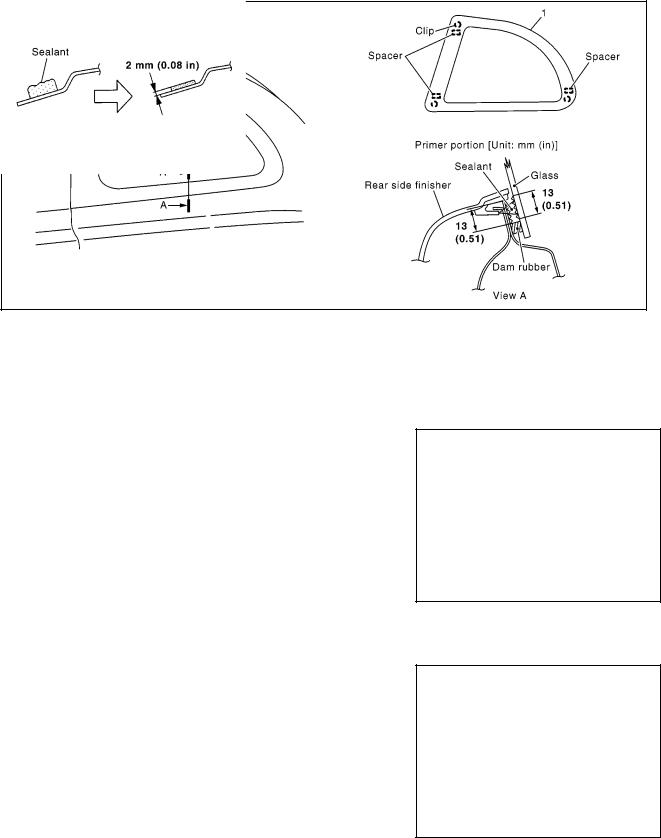
MIIB0177E
1. Windshield molding |
2. Windshield glass |
REMOVAL
1.Remove headlining. Refer to EI-33, "HEADLINER" .
2.Remove cowl top cover. Refer to EI-13, "COWL TOP" .
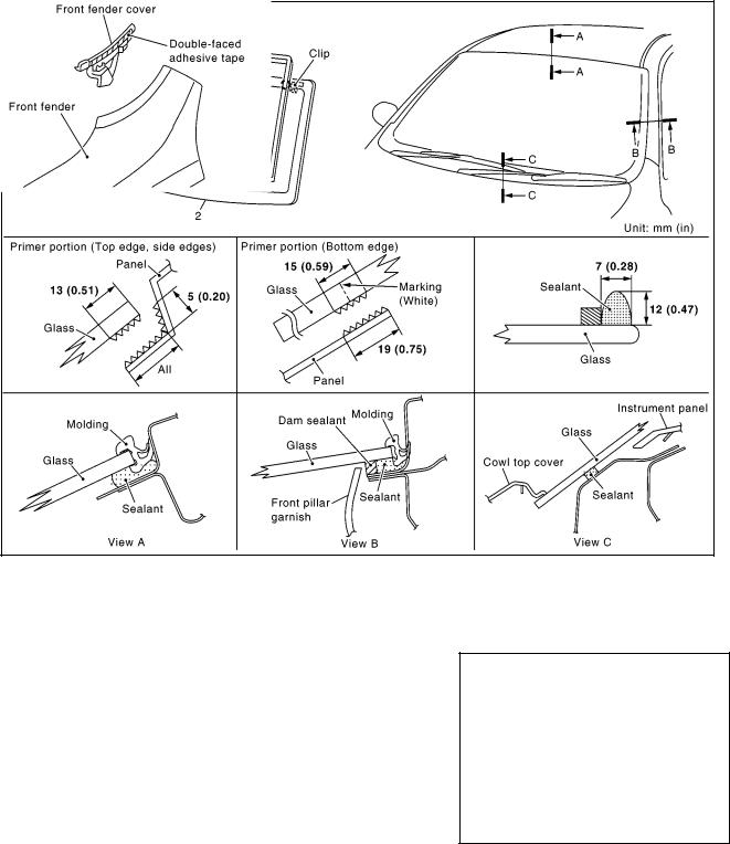
3.Peel off double-sided tape and remove front fender covers (LH/ RH) from front fenders (LH/RH).
MIIB0063E
4.Apply protective tape around windshield glass to protect the painted surface from damage.
5.Guiding a cutter knife along glass, cut the surface of moldings.
6.With pliers, draw out all the remaining molding left in flanged area of body to remove it completely from adhering surface on glass.
GW-6
WINDSHIELD GLASS
[HATCHBACK]
●When re-using the windshield glass, put match marks on body and glass.
MIIB0178E
7.Cut adhesive.
● Depending on the tool in use, follow the procedures below:
CAUTION:
If windshield glass is reused, do not use a windshield knife. (It may scratch glass surface.)
a.With a windshield knife (when replacing glass).
i.To smoothly cut with windshield knife, apply soapy water onto the adhesive on the body side surrounding the windshield.
ii.Insert windshield knife into the bonded area. Cut adhesive by pulling the knife, keeping the tip parallel to glass edge.
b.With a piano wire (when reusing glass).
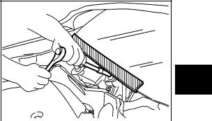
i.Working from inside cabin, drill a through hole in the adhesive with a drill or pick.
ii.From inside the passenger room, pass a piano wire through the hole and tie both ends to screwdrivers or similar tools.
iii.With two persons, one holding one end of the piano wire outside the vehicle while the other holding the other end inside the vehicle, pulling the wire alternately to cut off the adhesive.
CAUTION:
●Do not press piano wire excessively against glass edge.
●Put a copper plate to keep the piano wire clear of plastic parts such as the instrument panel.
8.Use rubber suction cups (SST) to remove glass from the vehicle.
MIIB0179E
MIIB0180E
BEC2267D
A
B
C
D
E
F
G
H
GW
J
K
L
M
GW-7
WINDSHIELD GLASS
[HATCHBACK]
INSTALLATION
1.Using a knife or spatula, trim the adhesive (sealant) remaining on body down to approximately 2 mm thick so that the contour becomes smooth.
CAUTION:
If bonded area on body is scratched, be sure to repair it with a 2-component urethane. Do not use lacquer.
MIIB0181E
2.Put the clip in the panel hole.
3.When installing new glass, mount glass onto the vehicle and paint mating marks on body and glass, then remove glass again.
4.When reusing glass, use a knife or spatula to remove the remaining adhesive (sealant) and smooth out the surface.
5.Clean bonded area on glass with white gasoline.
MIIB0182E
6.Apply primer G along the entire circumference of glass.
CAUTION:
There are 2 types of primer. Never confuse the application methods. Primer M: for painted surfaces
Primer G: for glass
NOTE:
The essential function of primers is to strengthen adhesion between glass and painted surface.
7.Apply primer M on areas where adhesive contacts on the side of vehicle body.
CAUTION:
●If primer M adheres to a painted surface other than bonding area, or if it overflows, quickly remove it with white gasoline.
●Place a copper plate to keep primer M clear of the instrument panel.
8.After applying primers, apply the adhesive along the entire circumference of the glass as shown in the figure, and within the time specified in the instructions for the adhesive.
●Open adhesive by cutting off the nozzle tip and set it in a sealant gun.
9.After setting rubber suction cups (SST) to glass, align mating marks on body and glass. Install glass to the body.
10.Press entire surface of glass lightly to fit it completely.
11.Remove protective tape.
12.Using a spatula, repair any adhesive overflow or shortage to make the surface smooth.
MIIB0183E
13.Position windshield moldings and allow their adhesion. Refer to EI-16, "WINDSHIELD MOLDING" .
CAUTION:
●Be sure to install windshield molding before adhesive hardens.
●After installing glass, keep door windows open and avoid driving vehicle until adhesive has completely cured.
GW-8

WINDSHIELD GLASS
[HATCHBACK]
14.Check for water leaks.
15.Remove double-sided tape from front fender cover and apply primer (Sumitomo 3M K520) to double-sided tape application position shown in the figure. Then apply new double-sided tape and install front fender.
Double-sided adhesive |
: Part equivalent to Sumit- |
tape |
omo 3M-5571 (t: 0.8) |
16.Install cowl top cover. Refer to EI-13, "COWL TOP" .
17.Install headlining. Refer to EI-33, "HEADLINER" .
A
B
C
D
MIIB0067E
E
F
G
H
GW
J
K
L
M
GW-9
|
SIDE WINDOW GLASS |
|
[HATCHBACK] |
|
|
SIDE WINDOW GLASS |
PFP:83300 |
Removal and Installation |
EIS004K8 |
MIIB0904E
1.Side window glass
REMOVAL
1.Remove rear side finisher and lock pillar upper garnish. Refer to EI-26, "Removal and Installation (3- Door)" .
2.Apply protective tape on body panel along the circumference side window glass to protect coated surfaces from damage.
3.For the side window glass vehicle front side, open front door, and from outside of vehicle insert cutter knife between side window glass and lock pillar panel and cut adhesive parallel to glass.
4.For side window glass adhesion areas other than the above, working from inside vehicle, insert cutter knife between side door window glass and body panel. Guide cutter edge along glass to cut off adhesive.
CAUTION: |
|
Cut carefully so that the tip end of cutter knife does not |
|
contact painted surface. |
BEC2418D |
5.Remove glass out of vehicle, unclipping.
INSTALLATION
1.With a knife, scrape off adhesive remaining on the vehicle body to as thin and flat as 2 mm.
CAUTION:
If scratches are made on vehicle-side bonding surface, be sure to repair it. Always use 2-component type urethane paint. Do not use lacquer type paint.
2.Using a knife or spatula to remove the remaining adhesive and smooth out the surface. (When glass is reused)
3.Clean bonded area on glass with white gasoline.
4.Apply primer G along the entire circumference of glass.
MIIB0181E
CAUTION:
As 2 primers will be used, they must be used exactly as specified.
Primer M: for painted surfaces
GW-10
SIDE WINDOW GLASS
[HATCHBACK]
Primer G: for glass
NOTE:
The essential function of primers is to strengthen adhesion between the glass and painted surface primer.
5.Apply primer M on areas where adhesive contacts on the side of vehicle body.
CAUTION:
If primer M adheres to a painted surface other than bonding area, or if it overflows, quickly remove it with white gasoline.
6.After applying primers, apply the adhesive along the entire circumference of the glass as shown in the figure, and within the time specified in the instructions for the adhesive.
●Open adhesive by cutting off the nozzle tip and set it in a sealant gun.
MIIB0185E
7.After setting rubber suction cups (SST) to glass, align mating marks on body and glass. Install glass to the body.
8.Press entire surface of glass lightly to fit it completely.
9.Remove protective tape.
10.Using a spatula, go over areas with excessive or insufficient adhesive and neatly smooth the surface.
CAUTION:
After installing glass, keep door windows open and avoid driving vehicle until adhesive has completely cured.
11. Check for water leaks. |
BEC2420D |
12.Install rear side finisher and lock pillar upper garnish. Refer to EI-26, "Removal and Installation (3-Door)" .
A
B
C
D
E
F
G
H
GW
J
K
L
M
GW-11
BACK DOOR WINDOW GLASS
|
[HATCHBACK] |
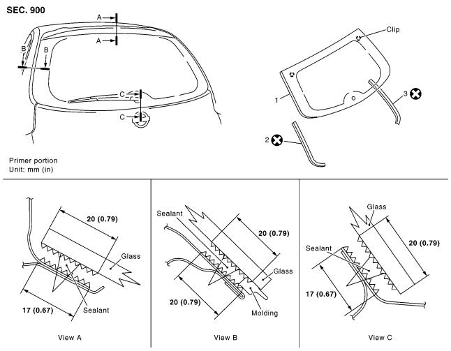
BACK DOOR WINDOW GLASS |
PFP:90300 |
Removal and Installation |
EIS004K9 |
|
MIIB0186E |
1. Back door window glass |
2. Back door window molding (LH side) 3. Back door window molding (RH side) |
REMOVAL
1.Remove back door finisher. Refer to EI-22, "BACK DOOR TRIM" .
2.Remove high mounted stop lamp. Refer to LT-203, "Bulb Replacement" .
3.Remove rear wiper arm and rear wiper motor. Refer to WW-109, "Removal and Installation of Rear Wiper Arm" and WW-109, "Removal and Installation of Rear Wiper Motor"
4.Disconnect rear window defogger connector.
5.Apply protective tape around windshield glass to protect the painted surface from damage.
6.Cut adhesive.
●Depending on the tool in use, follow the procedures below:
CAUTION:
When reusing the glass, do not use the windshield knife. (Because it will damage the glass)
GW-12

BACK DOOR WINDOW GLASS
|
|
[HATCHBACK] |
||
a. |
With a windshield knife (when replacing glass). |
|
|
A |
|
|
|||
i. |
For smooth movement of windshield knife, apply soapy water |
|
|
|
|
around bonded area on glass hatch panel. |
|
|
|
ii. |
Insert windshield knife into the bonded area from passenger |
|
|
|
|
room side. Cut adhesive by pulling the knife, keeping the tip par- |
|
|
B |
|
allel to glass edge. |
|
|
|
|
|
|
|
C |
|
|
MIIB0187E |
|
|
b.With a piano wire (when reusing glass).
i.Working from inside the passenger room, make a hole in the adhesive with the cutter.
ii.From inside the passenger room, pass a piano wire through the hole and tie both ends to screwdrivers or similar tools.
iii.With two persons, one holding one end of the piano wire outside the vehicle while the other holding the other end inside the vehicle, pulling the wire alternately to cut off the adhesive.
CAUTION:
●Do not press piano wire excessively against glass edge.
7.Unclip and remove glass from the vehicle with rubber suction cups (SST).
MIIB0188E
BEC2420D
D
E
F
G
H
GW
J
K
INSTALLATION
1.Using a knife or spatula, trim the bond remaining on body down to approximately 2 mm thick so that the contour becomes smooth.
CAUTION:
If scratches or flaws are made on the body surface in the width of adhesion, be sure to repair them with 2-liquid type urethane paint. Do not use lacquer type paint.
2.When reusing glass, use a knife or spatula to remove the remaining adhesive and smooth out the surface.
3.With white gasoline, clean the glass surface where adhesive is
applied and the surrounding areas. |
MIIB0181E |
|
L
M
GW-13

BACK DOOR WINDOW GLASS
[HATCHBACK]
4.Bond the back door window molding to the perimeter of the glass using double-sided tape. (Bond aligning double-sided tape bonded area to glass edge.)
MIIB0189E
5.Apply primer G along the entire circumference of glass.
CAUTION:
As 2 primers will be used, they must be used exactly as specified. Primer M: for painted surfaces
Primer G: for glass
NOTE:
The essential function of primers is to strengthen adhesion between the glass and painted surface primer.
6.Apply primer M on areas where adhesive contacts on the side of vehicle body.
CAUTION:
If primer M adheres to a painted surface other than bonding area, or if it overflows, quickly remove it with white gasoline.
7.After applying primers, apply the adhesive along the entire circumference of the glass as shown in the figure, and within the time specified in the instructions for the adhesive.
●Open adhesive by cutting off the nozzle tip and set it in a sealant gun.
MIIB0185E
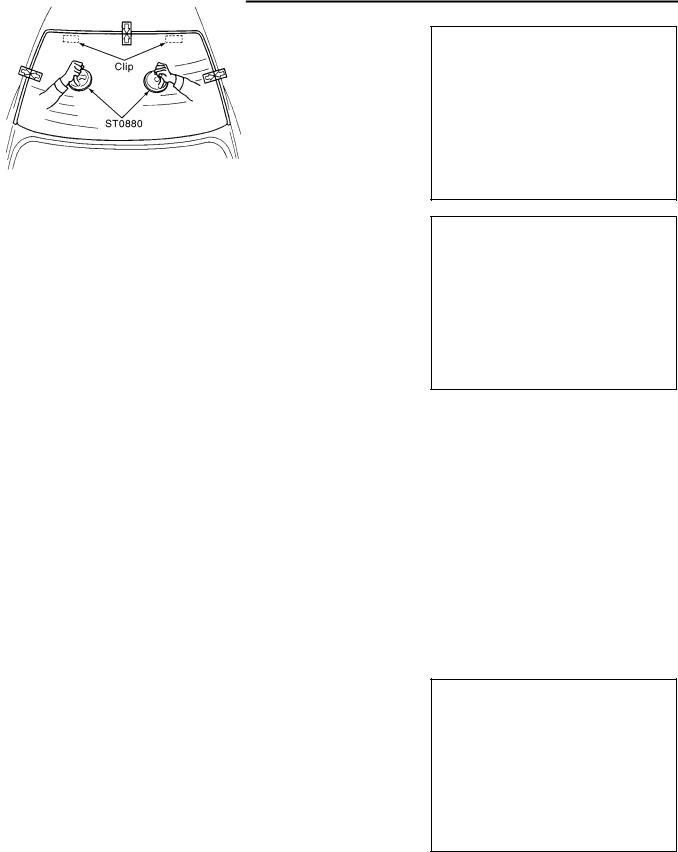
8.After setting rubber suction cups (SST) to glass, align the clips with the holes on the body panel and install.
BEC2420D
9.Press entire surface of glass lightly to fit it completely.
10.Remove protective tape.
11.Using a spatula, repair any adhesive overflow or shortage and make the surface smooth.
CAUTION:
After installing glass, keep door windows open and avoid driving vehicle until adhesive has completely cured.
12.Check for water leaks.
13.Connect rear window defogger connector.
GW-14
BACK DOOR WINDOW GLASS
[HATCHBACK] |
|
|
14. Install rear wiper arm and rear wiper motor. Refer to WW-109, "Removal and Installation of Rear Wiper |
|
|
Arm" and WW-109, "Removal and Installation of Rear Wiper Motor" . |
|
A |
15. Install high-mounted stop lamp. Refer to LT-203, "Bulb Replacement" . |
|
|
16. Install back door finisher. Refer to EI-22, "BACK DOOR TRIM" . |
|
|
|
|
B |
|
|
C |
|
|
D |
|
|
E |
|
|
F |
|
|
G |
|
|
H |
|
|
|
|
|
GW |
|
|
|
|
|
J |
|
|
K |
|
|
L |
|
|
M |
GW-15

REAR WINDOW DEFOGGER
|
[HATCHBACK] |
REAR WINDOW DEFOGGER |
PFP:25350 |
Component Parts and Harness Connector Location |
EIS004KA |
System Description
MIIB0228E
EIS004KB
The rear window defogger system is controlled by BCM (Body Control Module) and IPDM E/R (Intelligent Power Distribution Module Engine Room).
The rear window defogger operates only for approximately 15 minutes. Power is at all times supplied
●through 15A fuse [No. 45, and 46, located in the IPDM E/R]
●to rear window defogger relay
●through 20A fuse [No. 52, located in the fuse block (J/B)]
●to IPDM E/R
●through 40A fusible link [letter J , located in the fuse block (J/B)]
●to BCM terminal 74 and 79.
With the ignition switch turned to ON or START position,
Power is supplied
●through 10A fuse [No. 4, located in the fuse block (J/B)]
●to BCM terminal 24
Ground is supplied
●to BCM terminal 2 and 70
●through body grounds M19, and M20.
●to A/C auto amp terminal 14 (with auto A/C) or
●to heater control panel terminal 10 (without auto A/C)
GW-16

REAR WINDOW DEFOGGER
[HATCHBACK]
●through body grounds M19 and M20.
●to internal CPU of IPDM E/R terminal 3 and 54
●through body grounds E26 and E40. (without CR engine)
●through body grounds E25, E26 and E40. (with CR engine)
When rear window defogger switch is turned to ON,
Ground is supplied
●to BCM terminal 4
●through A/C auto amp terminal 17 (with auto A/C) or
●through heater control panel terminal 9 (without auto A/C)
●through A/C auto amp terminal 14 (with auto A/C) or
●through heater control panel terminal 10 (without auto A/C)
●through body grounds M19 and M20.
Then rear window defogger switch is illuminated.
Then BCM recognizes that rear window defogger switch is turned to ON.
Then it sends rear window defogger switch signals to IPDM E/R via DATA LINE (CAN-H, CAN-L). When IPDM receives rear window defogger switch signals,
Ground is supplied
●to rear window defogger relay terminal
●through internal CPU of IPDM E/R terminal
●through internal CPU of IPDM E/R and IPDM E/R terminal 54
●through body grounds E26 and E40. (without CR engine)
●through body grounds E25, E26 and E40. (with CR engine)
and then rear window defogger relay is energized. When rear window defogger relay is turned ON, Power is supplied,
●through rear window defogger relay terminals
●through IPDM E/R terminal 8
●to rear window defogger terminal 1.
Rear window defogger terminal 2, is grounded through body ground D202.
With power and ground supplied, rear window defogger filaments heat and defog the rear window. When rear window defogger relay is turned to ON,
Power is supplied (with mirror defogger)
●through rear window defogger relay terminal
●through IPDM E/R terminal 8
●through 10A fuse [No. 13, located in the fuse block (J/B)]
●to door mirror defogger (Driver side and passenger side) terminal 6.
Door mirror defogger (Driver side and passenger side) terminal 5 is grounded through body grounds M19 and M20.
With power and ground supplied, door mirror defogger filaments heat and defog the mirror.
A
B
C
D
E
F
G
H
GW
J
K
L
M
GW-17

REAR WINDOW DEFOGGER
[HATCHBACK]
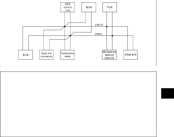
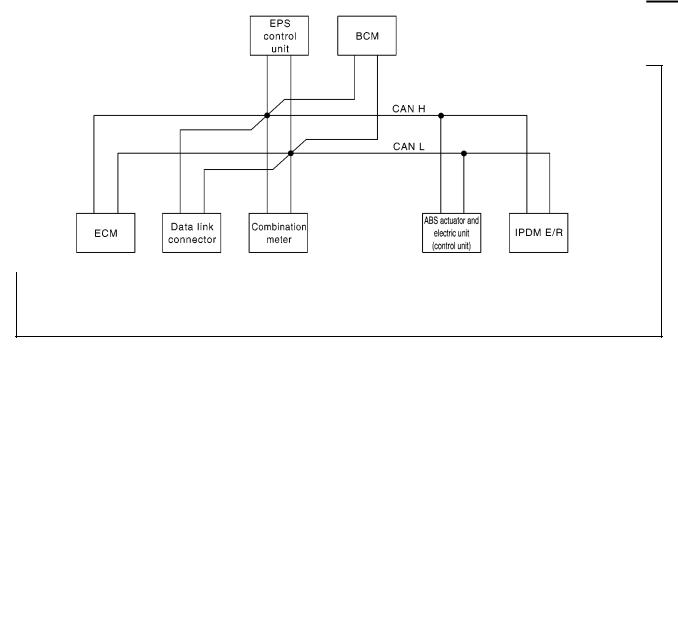
CAN Communication |
EIS00AOW |
SYSTEM DESCRIPTION
CAN (Controller Area Network) is a serial communication line for real time application. It is an on-vehicle multiplex communication line with high data communication speed and excellent error detection ability. Many electronic control units are equipped onto a vehicle, and each control unit shares information and links with other control units during operation (not independent). In CAN communication, control units are connected with 2 communication lines (CAN H line, CAN L line) allowing a high rate of information transmission with less wiring. Each control unit transmits/receives data but selectively reads required data only.
CAN Communication Unit |
|
|
|
|
|
|
|
|
|
|
|
|
|
|
|
|
|
EIS00E76 |
|||||
|
|
|
|
|
|
|
|
|
|
|
|
|
|
|
|
|
|
|
|||||
Body type |
3door/5door |
|
3door/5door/C+C |
|
3door/5door |
|
3door/5door/C+C |
|
3door/5door |
||||||||||||||
|
|
|
|
|
|
|
|
|
|
|
|
|
|
|
|
|
|
|
|
|
|
|
|
Axle |
|
|
|
|
|
|
|
|
|
|
|
2WD |
|
|
|
|
|
|
|
|
|
||
|
|
|
|
|
|
|
|
|
|
|
|
|
|
|
|
||||||||
Engine |
|
CR12DE/CR14DE |
|
HR16DE |
|
CR12DE/CR14DE |
HR16DE |
|
K9K |
||||||||||||||
|
|
|
|
|
|
|
|
|
|
|
|
|
|
|
|
|
|
|
|
|
|
||
Handle |
|
|
|
|
|
|
|
|
|
|
LHD/RHD |
|
|
|
|
|
|
|
|
|
|||
|
|
|
|
|
|
|
|
|
|
|
|
|
|
|
|
|
|
|
|
|
|
||
Brake control |
|
|
|
|
ABS |
|
|
|
|
|
|
|
|
ESP |
|
|
|
|
ABS |
||||
|
|
|
|
|
|
|
|
|
|
|
|
|
|
|
|
|
|
|
|
|
|
||
Transmission |
|
A/T |
|
|
|
M/T |
|
|
A/T |
|
|
|
M/T |
|
|
|
|
||||||
|
|
|
|
|
|
|
|
|
|
|
|
|
|
|
|
|
|
|
|
|
|
|
|
Intelligent Key system |
× |
|
|
× |
|
|
|
× |
|
|
× |
|
|
× |
|
|
× |
|
|
× |
|
|
|
|
|
|
|
|
|
|
|
|
|
|
|
|
|
|
|
|
|
|
|
|
|||
|
|
|
|
|
|
|
CAN communication unit |
|
|
|
|
|
|
|
|
|
|||||||
|
|
|
|
|
|
|
|
|
|
|
|
|
|
|
|
|
|
|
|
|
|
|
|
ECM |
× |
|
× |
× |
|
× |
|
× |
|
× |
× |
|
× |
× |
|
× |
× |
|
× |
× |
|
× |
|
|
|
|
|
|
|
|
|
|
|
|
|
|
|
|
|
|
|
|
|
|
|
|
|
Data link connector |
× |
|
× |
× |
|
× |
|
× |
|
× |
× |
|
× |
× |
|
× |
× |
|
× |
× |
|
× |
|
|
|
|
|
|
|
|
|
|
|
|
|
|
|
|
|
|
|
|
|
|
|
|
|
Combination meter |
× |
|
× |
× |
|
× |
|
× |
|
× |
× |
|
× |
× |
|
× |
× |
|
× |
× |
|
× |
|
|
|
|
|
|
|
|
|
|
|
|
|
|
|
|
|
|
|
|
|
|
|
|
|
Intelligent Key unit |
× |
|
|
× |
|
|
|
× |
|
|
× |
|
|
× |
|
|
× |
|
|
× |
|
|
|
|
|
|
|
|
|
|
|
|
|
|
|
|
|
|
|
|
|
|
|
|
|
|
|
EPS control unit |
× |
|
× |
× |
|
× |
|
× |
|
× |
× |
|
× |
× |
|
× |
× |
|
× |
× |
|
× |
|
|
|
|
|
|
|
|
|
|
|
|
|
|
|
|
|
|
|
|
|
|
|
|
|
BCM |
× |
|
× |
× |
|
× |
|
× |
|
× |
× |
|
× |
× |
|
× |
× |
|
× |
× |
|
× |
|
|
|
|
|
|
|
|
|
|
|
|
|
|
|
|
|
|
|
|
|
|
|
|
|
ABS actuator and |
|
|
|
|
|
|
|
|
|
|
|
|
|
|
|
|
|
|
|
|
|
|
|
electric unit (control |
× |
|
× |
× |
|
× |
|
× |
|
× |
× |
|
× |
× |
|
× |
× |
|
× |
× |
|
× |
|
unit) |
|
|
|
|
|
|
|
|
|
|
|
|
|
|
|
|
|
|
|
|
|
|
|
|
|
|
|
|
|
|
|
|
|
|
|
|
|
|
|
|
|
|
|
|
|
|
|
TCM |
× |
|
× |
|
|
|
|
|
|
|
× |
|
× |
|
|
|
|
|
|
|
|
|
|
|
|
|
|
|
|
|
|
|
|
|
|
|
|
|
|
|
|
|
|
|
|
|
|
IPDM E/R |
× |
|
× |
× |
|
× |
|
× |
|
× |
× |
|
× |
× |
|
× |
× |
|
× |
× |
|
× |
|
|
|
|
|
|
|
|
|
|
|
|
|
|
|
|
|
|
|
|
|
||||
CAN communication |
GW-19, |
GW-22, "TYPE 3/TYPE 4/ |
GW-24, |
GW-27, "TYPE 9/TYPE 10/ |
GW-29, |
||||||||||||||||||
"TYPE 1/ |
"TYPE 7/ |
"TYPE 13/ |
|||||||||||||||||||||
type |
|
TYPE 5/TYPE 6" |
|
|
TYPE 11/TYPE 12" |
|
|||||||||||||||||
TYPE 2" |
|
|
TYPE 8" |
|
|
TYPE 14" |
|||||||||||||||||
|
|
|
|
|
|
|
|
|
|
|
|
|
|
||||||||||
|
|
|
|
|
|
|
|
|
|
|
|
|
|
|
|
|
|
|
|
|
|
|
|
×: Applicable
GW-18
|
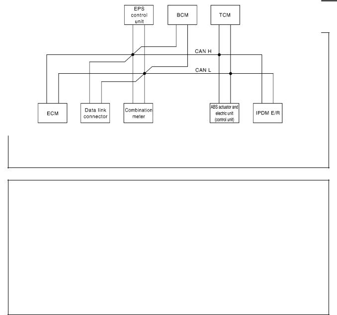
REAR WINDOW DEFOGGER |
|
|
[HATCHBACK] |
|
|
|
|
TYPE 1/TYPE 2 |
|
|
System diagram |
|
A |
●Type 1
B
C
D
E
F
|
|
MKIB1735E |
|
● Type 2 |
|
G |
|
H
GW
J
K
L
MKIB1736E
Input/output signal chart
T: Transmit R: Receive M
|
|
|
|
|
|
ABS |
|
|
|
|
|
|
|
|
|
actua- |
|
|
|
|
|
Combi- |
Intelli- |
EPS |
|
tor and |
|
IPDM |
|
Signals |
ECM |
nation |
gent |
control |
BCM |
electric |
TCM |
||
E/R |
|||||||||
|
|
meter. |
Key unit |
unit |
|
unit |
|
||
|
|
|
|
|
|||||
|
|
|
|
|
|
(control |
|
|
|
|
|
|
|
|
|
unit) |
|
|
|
|
|
|
|
|
|
|
|
|
|
Engine speed signal |
T |
R |
|
|
|
|
|
|
|
|
|
|
|
|
|
|
|
|
|
Engine coolant temperature signal |
T |
R |
|
|
|
|
|
|
|
|
|
|
|
|
|
|
|
|
|
A/T self-diagnosis signal |
R |
|
|
|
|
|
T |
|
|
|
|
|
|
|
|
|
|
|
|
Output shaft revolution signal |
R |
|
|
|
|
|
T |
|
|
|
|
|
|
|
|
|
|
|
|
Accelerator pedal position signal |
T |
|
|
|
|
|
R |
|
|
|
|
|
|
|
|
|
|
|
|
Closed throttle position signal |
T |
|
|
|
|
|
R |
|
|
|
|
|
|
|
|
|
|
|
|
Wide open throttle position signal |
T |
|
|
|
|
|
R |
|
|
|
|
|
|
|
|
|
|
|
|
Overdrive control switch signal |
|
T |
|
|
|
|
R |
|
|
|
|
|
|
|
|
|
|
|
GW-19

REAR WINDOW DEFOGGER
[HATCHBACK]
|
|
|
|
|
|
ABS |
|
|
|
|
|
|
|
|
|
actua- |
|
|
|
|
|
Combi- |
Intelli- |
EPS |
|
tor and |
|
IPDM |
|
Signals |
ECM |
nation |
gent |
control |
BCM |
electric |
TCM |
||
E/R |
|||||||||
|
|
meter. |
Key unit |
unit |
|
unit |
|
||
|
|
|
|
|
|||||
|
|
|
|
|
|
(control |
|
|
|
|
|
|
|
|
|
unit) |
|
|
|
|
|
|
|
|
|
|
|
|
|
A/T position indicator signal |
|
R |
|
|
|
|
T |
|
|
|
|
|
|
|
|
|
|
|
|
Stop lamp switch signal |
|
T |
|
|
|
|
R |
|
|
|
|
|
|
|
|
|
|
|
|
O/D OFF indicator signal |
|
R |
|
|
|
|
T |
|
|
|
|
|
|
|
|
|
|
|
|
Engine and A/T integrated control signal |
T |
|
|
|
|
|
R |
|
|
|
|
|
|
|
|
|
|
||
R |
|
|
|
|
|
T |
|
||
|
|
|
|
|
|
|
|||
|
|
|
|
|
|
|
|
|
|
Fuel consumption monitor signal |
T |
R |
|
|
|
|
|
|
|
|
|
|
|
|
|
|
|
|
|
Oil pressure switch signal |
|
R |
|
|
|
|
|
T |
|
|
|
|
|
|
|
|
|
|
|
A/C compressor request signal |
T |
|
|
|
|
|
|
R |
|
|
|
|
|
|
|
|
|
|
|
Heater fan switch signal |
R |
|
|
|
T |
|
|
|
|
|
|
|
|
|
|
|
|
|
|
Cooling fan speed request signal |
T |
|
|
|
|
|
|
R |
|
|
|
|
|
|
|
|
|
|
|
Position lights request signal |
|
R |
|
|
T |
|
|
R |
|
|
|
|
|
|
|
|
|
|
|
Low beam request signal |
|
|
|
|
T |
|
|
R |
|
|
|
|
|
|
|
|
|
|
|
Low beam status signal |
R |
|
|
|
|
|
|
T |
|
|
|
|
|
|
|
|
|
|
|
High beam request signal |
|
R |
|
|
T |
|
|
R |
|
|
|
|
|
|
|
|
|
|
|
High beam status signal |
R |
|
|
|
|
|
|
T |
|
|
|
|
|
|
|
|
|
|
|
Day time light request signal |
|
|
|
|
T |
|
|
R |
|
|
|
|
|
|
|
|
|
|
|
Vehicle speed signal |
R |
R |
|
R |
|
T |
|
|
|
|
|
|
|
|
|
|
|
||
R |
T |
R |
R |
R |
|
|
|
||
|
|
|
|
||||||
|
|
|
|
|
|
|
|
|
|
Sleep/wake up signal |
|
R |
R |
|
T |
|
|
R |
|
|
|
|
|
|
|
|
|
|
|
Door switch signal |
|
R |
R |
|
T |
|
|
R |
|
|
|
|
|
|
|
|
|
|
|
Turn indicator signal |
|
R |
|
|
T |
|
|
|
|
|
|
|
|
|
|
|
|
|
|
Buzzer output signal |
|
R |
|
|
T |
|
|
|
|
|
|
|
|
|
|
|
|
||
|
R |
T |
|
|
|
|
|
||
|
|
|
|
|
|
|
|||
|
|
|
|
|
|
|
|
|
|
MI signal |
T |
R |
|
|
|
|
|
|
|
|
|
|
|
|
|
|
|
|
|
Front wiper request signal |
|
|
|
|
T |
|
|
R |
|
|
|
|
|
|
|
|
|
|
|
Front wiper stop position signal |
|
|
|
|
R |
|
|
T |
|
|
|
|
|
|
|
|
|
|
|
Rear window defogger switch signal |
|
|
|
|
T |
|
|
R |
|
|
|
|
|
|
|
|
|
|
|
Rear window defogger control signal |
R |
|
|
|
|
|
|
T |
|
|
|
|
|
|
|
|
|
|
|
EPS warning lamp signal |
|
R |
|
T |
|
|
|
|
|
|
|
|
|
|
|
|
|
|
|
ABS warning lamp signal |
|
R |
|
|
|
T |
|
|
|
|
|
|
|
|
|
|
|
|
|
Brake warning lamp signal |
|
R |
|
|
|
T |
|
|
|
|
|
|
|
|
|
|
|
|
|
Back-up lamp signal |
|
|
|
R |
T |
|
|
|
|
|
|
|
|
|
|
|
|
|
|
Front fog lamp request signal |
|
R |
|
|
T |
|
|
R |
|
|
|
|
|
|
|
|
|
|
|
Rear fog lamp status signal |
|
R |
|
|
T |
|
|
|
|
|
|
|
|
|
|
|
|
|
|
Headlamp washer request signal |
|
|
|
|
T |
|
|
R |
|
|
|
|
|
|
|
|
|
|
|
Door lock/unlock request signal |
|
|
T |
|
R |
|
|
|
|
|
|
|
|
|
|
|
|
|
|
Door lock/unlock status signal |
|
|
R |
|
T |
|
|
|
|
|
|
|
|
|
|
|
|
|
|
KEY indicator signal |
|
R |
T |
|
|
|
|
|
|
|
|
|
|
|
|
|
|
|
|
LOCK indicator signal |
|
R |
T |
|
|
|
|
|
|
|
|
|
|
|
|
|
|
|
|
Engine status signal |
T |
|
|
R |
|
|
|
|
|
|
|
|
|
|
|
|
|
|
GW-20
REAR WINDOW DEFOGGER
|
|
|
|
|
|
|
[HATCHBACK] |
||
|
|
|
|
|
|
|
|
|
|
|
|
|
|
|
|
|
ABS |
|
|
|
|
|
|
|
|
|
actua- |
|
|
|
|
|
Combi- |
Intelli- |
EPS |
|
tor and |
|
IPDM |
|
Signals |
ECM |
nation |
gent |
control |
BCM |
electric |
TCM |
|
|
E/R |
||||||||
|
|
|
meter. |
Key unit |
unit |
|
unit |
|
|
|
|
|
|
|
|
||||
|
|
|
|
|
|
|
(control |
|
|
|
|
|
|
|
|
|
unit) |
|
|
|
|
|
|
|
|
|
|
|
|
|
A/C switch signal |
R |
|
|
|
T |
|
|
|
|
|
|
|
|
|
|
|
|
|
|
Brake system malfunction signal |
|
T |
|
R |
|
|
|
|
|
|
|
|
|
|
|
|
|
|
|
Parking brake switch signal |
|
T |
|
R |
|
|
|
|
|
|
|
|
|
|
|
|
|
|
|
R range signal |
|
|
|
|
R |
|
|
T |
|
|
|
|
|
|
|
|
|
|
A
B
C
D
E
F
G
H
GW
J
K
L
M
GW-21
REAR WINDOW DEFOGGER
[HATCHBACK]
TYPE 3/TYPE 4/TYPE 5/TYPE 6
System diagram
●Type 3/Type 5
MKIB1737E
●Type 4/Type 6
|
|
|
|
|
|
|
|
|
MKIB1738E |
|
Input/output signal chart |
|
|
|
|
|
|
|
|
|
|
|
|
|
|
|
|
|
T: Transmit |
R: Receive |
||
|
|
|
|
|
|
|
|
|
|
|
|
|
|
|
|
|
|
ABS actu- |
|
|
|
|
|
|
Combina- |
Intelligent |
EPS con- |
|
ator and |
|
|
|
|
Signals |
ECM |
BCM |
electric |
|
IPDM E/R |
||||
|
tion meter. |
Key unit |
trol unit |
|
||||||
|
|
|
|
unit (con- |
|
|
|
|||
|
|
|
|
|
|
|
|
|
|
|
|
|
|
|
|
|
|
trol unit) |
|
|
|
|
|
|
|
|
|
|
|
|
|
|
Engine speed signal |
T |
R |
|
|
|
|
|
|
|
|
|
|
|
|
|
|
|
|
|
|
|
Engine coolant temperature signal |
T |
R |
|
|
|
|
|
|
|
|
|
|
|
|
|
|
|
|
|
|
|
Fuel consumption monitor signal |
T |
R |
|
|
|
|
|
|
|
|
|
|
|
|
|
|
|
|
|
||
Oil pressure switch signal |
|
R |
|
|
|
|
|
T |
||
|
|
|
|
|
|
|
|
|
||
A/C compressor request signal |
T |
|
|
|
|
|
|
R |
||
|
|
|
|
|
|
|
|
|
|
|
Heater fan switch signal |
R |
|
|
|
T |
|
|
|
|
|
|
|
|
|
|
|
|
|
|
||
Cooling fan speed request signal |
T |
|
|
|
|
|
|
R |
||
|
|
|
|
|
|
|
|
|
||
Position lights request signal |
|
R |
|
|
T |
|
|
R |
||
|
|
|
|
|
|
|
|
|
||
Low beam request signal |
|
|
|
|
T |
|
|
R |
||
|
|
|
|
|
|
|
|
|
|
|
GW-22

REAR WINDOW DEFOGGER
[HATCHBACK]
|
|
|
|
|
|
ABS actu- |
|
|
|
|
Combina- |
Intelligent |
EPS con- |
|
ator and |
|
|
Signals |
ECM |
BCM |
electric |
IPDM E/R |
||||
tion meter. |
Key unit |
trol unit |
||||||
|
|
|
unit (con- |
|
||||
|
|
|
|
|
|
|
||
|
|
|
|
|
|
trol unit) |
|
|
|
|
|
|
|
|
|
|
|
Low beam status signal |
R |
|
|
|
|
|
T |
|
|
|
|
|
|
|
|
|
|
High beam request signal |
|
R |
|
|
T |
|
R |
|
|
|
|
|
|
|
|
|
|
High beam status signal |
R |
|
|
|
|
|
T |
|
|
|
|
|
|
|
|
|
|
Day time light request signal |
|
|
|
|
T |
|
R |
|
|
|
|
|
|
|
|
|
|
Vehicle speed signal |
R |
R |
|
R |
|
T |
|
|
|
|
|
|
|
|
|
||
R |
T |
R |
R |
R |
|
|
||
|
|
|
||||||
|
|
|
|
|
|
|
|
|
Sleep/wake up signal |
|
R |
R |
|
T |
|
R |
|
|
|
|
|
|
|
|
|
|
Door switch signal |
|
R |
R |
|
T |
|
R |
|
|
|
|
|
|
|
|
|
|
Turn indicator signal |
|
R |
|
|
T |
|
|
|
|
|
|
|
|
|
|
|
|
Buzzer output signal |
|
R |
|
|
T |
|
|
|
|
|
|
|
|
|
|
||
|
R |
T |
|
|
|
|
||
|
|
|
|
|
|
|||
|
|
|
|
|
|
|
|
|
MI signal |
T |
R |
|
|
|
|
|
|
|
|
|
|
|
|
|
|
|
Front wiper request signal |
|
|
|
|
T |
|
R |
|
|
|
|
|
|
|
|
|
|
Front wiper stop position signal |
|
|
|
|
R |
|
T |
|
|
|
|
|
|
|
|
|
|
Rear window defogger switch signal |
|
|
|
|
T |
|
R |
|
|
|
|
|
|
|
|
|
|
Rear window defogger control signal |
R |
|
|
|
|
|
T |
|
|
|
|
|
|
|
|
|
|
EPS warning indicator signal |
|
R |
|
T |
|
|
|
|
|
|
|
|
|
|
|
|
|
ABS warning lamp signal |
|
R |
|
|
|
T |
|
|
|
|
|
|
|
|
|
|
|
Brake warning lamp signal |
|
R |
|
|
|
T |
|
|
|
|
|
|
|
|
|
|
|
Back-up lamp signal |
|
|
|
R |
T |
|
|
|
|
|
|
|
|
|
|
|
|
Front fog lamp request signal |
|
R |
|
|
T |
|
R |
|
|
|
|
|
|
|
|
|
|
Rear fog lamp status signal |
|
R |
|
|
T |
|
|
|
|
|
|
|
|
|
|
|
|
Headlamp washer request signal |
|
|
|
|
T |
|
R |
|
|
|
|
|
|
|
|
|
|
Door lock/unlock request signal |
|
|
T |
|
R |
|
|
|
|
|
|
|
|
|
|
|
|
Door lock/unlock status signal |
|
|
R |
|
T |
|
|
|
|
|
|
|
|
|
|
|
|
KEY indicator signal |
|
R |
T |
|
|
|
|
|
|
|
|
|
|
|
|
|
|
LOCK indicator signal |
|
R |
T |
|
|
|
|
|
|
|
|
|
|
|
|
|
|
Engine status signal |
T |
|
|
R |
|
|
|
|
|
|
|
|
|
|
|
|
|
A/C switch signal |
R |
|
|
|
T |
|
|
|
|
|
|
|
|
|
|
|
|
Brake system malfunction signal |
|
T |
|
R |
|
|
|
|
|
|
|
|
|
|
|
|
|
Parking brake switch signal |
|
T |
|
R |
|
|
|
|
|
|
|
|
|
|
|
|
|
R range signal |
|
|
|
|
R |
|
T |
|
|
|
|
|
|
|
|
|
|
Retractable hard top |
|
R |
|
|
T |
|
|
|
warning lamp signal* |
|
|
|
|
|
|||
|
|
|
|
|
|
|
||
|
|
|
|
|
|
|
|
|
*: C+C only |
|
|
|
|
|
|
|
A
B
C
D
E
F
G
H
GW
J
K
L
M
GW-23
REAR WINDOW DEFOGGER
[HATCHBACK]
TYPE 7/TYPE 8
System diagram
●Type 7
MKIB1735E
●Type 8
MKIB1736E
Input/output signal chart
|
|
|
|
|
|
|
T: Transmit R: Receive |
||
|
|
|
|
|
|
|
|
|
|
|
|
|
|
|
|
ABS |
|
|
|
|
|
Combina- |
Intelli- |
|
|
actuator |
|
|
|
|
|
EPS con- |
|
and elec- |
|
IPDM E/ |
|||
Signals |
ECM |
tion |
gent Key |
BCM |
TCM |
||||
trol unit |
tric unit |
R |
|||||||
|
|
meter. |
unit |
|
|
||||
|
|
|
|
(control |
|
|
|||
|
|
|
|
|
|
|
|
||
|
|
|
|
|
|
unit) |
|
|
|
|
|
|
|
|
|
|
|
|
|
Engine speed signal |
T |
R |
|
|
|
R |
|
|
|
|
|
|
|
|
|
|
|
|
|
Engine coolant temperature signal |
T |
R |
|
|
|
|
|
|
|
|
|
|
|
|
|
|
|
|
|
A/T self-diagnosis signal |
R |
|
|
|
|
|
T |
|
|
|
|
|
|
|
|
|
|
|
|
Output shaft revolution signal |
R |
|
|
|
|
|
T |
|
|
|
|
|
|
|
|
|
|
|
|
Accelerator pedal position signal |
T |
|
|
|
|
R |
R |
|
|
|
|
|
|
|
|
|
|
|
|
Closed throttle position signal |
T |
|
|
|
|
|
R |
|
|
|
|
|
|
|
|
|
|
|
|
Wide open throttle position signal |
T |
|
|
|
|
|
R |
|
|
|
|
|
|
|
|
|
|
|
|
Overdrive control switch signal |
|
T |
|
|
|
|
R |
|
|
|
|
|
|
|
|
|
|
|
|
A/T position indicator signal |
|
R |
|
|
|
|
T |
|
|
|
|
|
|
|
|
|
|
|
|
GW-24

REAR WINDOW DEFOGGER
|
|
|
|
|
|
|
|
[HATCHBACK] |
||
|
|
|
|
|
|
|
|
|
|
|
|
|
|
|
|
|
|
ABS |
|
|
|
|
|
|
Combina- |
Intelli- |
|
|
actuator |
|
|
|
|
|
|
EPS con- |
|
and elec- |
|
IPDM E/ |
|||
|
Signals |
ECM |
tion |
gent Key |
BCM |
TCM |
||||
|
trol unit |
tric unit |
R |
|||||||
|
|
|
meter. |
unit |
|
|
||||
|
|
|
|
|
(control |
|
|
|
||
|
|
|
|
|
|
|
|
|
|
|
|
|
|
|
|
|
|
unit) |
|
|
|
|
|
|
|
|
|
|
|
|
|
|
|
A/T shift schedule change demand |
|
|
|
|
|
T |
R |
|
|
|
signal |
|
|
|
|
|
|
|
||
|
|
|
|
|
|
|
|
|
|
|
|
|
|
|
|
|
|
|
|
|
|
|
Stop lamp switch signal |
|
T |
|
|
|
|
R |
|
|
|
|
|
|
|
|
|
|
|
|
|
|
O/D OFF indicator lamp signal |
|
R |
|
|
|
|
T |
|
|
|
|
|
|
|
|
|
|
|
|
|
|
Engine and A/T integrated control |
T |
|
|
|
|
|
R |
|
|
|
|
|
|
|
|
|
|
|
|
|
|
signal |
|
|
|
|
|
|
|
|
|
|
R |
|
|
|
|
|
T |
|
|
|
|
|
|
|
|
|
|
|
|
||
|
|
|
|
|
|
|
|
|
|
|
|
Fuel consumption monitor signal |
T |
R |
|
|
|
|
|
|
|
|
|
|
|
|
|
|
|
|
|
|
|
Oil pressure switch signal |
|
R |
|
|
|
|
|
T |
|
|
|
|
|
|
|
|
|
|
|
|
|
A/C compressor request signal |
T |
|
|
|
|
|
|
R |
|
|
|
|
|
|
|
|
|
|
|
|
|
Heater fan switch signal |
R |
|
|
|
T |
|
|
|
|
|
|
|
|
|
|
|
|
|
|
|
|
Cooling fan speed request signal |
T |
|
|
|
|
|
|
R |
|
|
|
|
|
|
|
|
|
|
|
|
|
Position lights request signal |
|
R |
|
|
T |
|
|
R |
|
|
|
|
|
|
|
|
|
|
|
|
|
Low beam request signal |
|
|
|
|
T |
|
|
R |
|
|
|
|
|
|
|
|
|
|
|
|
|
Low beam status signal |
R |
|
|
|
|
|
|
T |
|
|
|
|
|
|
|
|
|
|
|
|
|
High beam request signal |
|
R |
|
|
T |
|
|
R |
|
|
|
|
|
|
|
|
|
|
|
|
|
High beam status signal |
R |
|
|
|
|
|
|
T |
|
|
|
|
|
|
|
|
|
|
|
|
|
Day time light request signal |
|
|
|
|
T |
|
|
R |
|
|
|
|
|
|
|
|
|
|
|
|
|
Vehicle speed signal |
R |
R |
|
R |
|
T |
|
|
|
|
|
|
|
|
|
|
|
|
|
|
|
R |
T |
R |
R |
R |
|
|
|
|
|
|
|
|
|
|
|
|||||
|
|
|
|
|
|
|
|
|
|
|
|
Sleep/wake up signal |
|
R |
R |
|
T |
|
|
R |
|
|
|
|
|
|
|
|
|
|
|
|
|
Door switch signal |
|
R |
R |
|
T |
|
|
R |
|
|
|
|
|
|
|
|
|
|
|
|
|
Turn indicator signal |
|
R |
|
|
T |
|
|
|
|
|
|
|
|
|
|
|
|
|
|
|
|
Buzzer output signal |
|
R |
|
|
T |
|
|
|
|
|
|
|
|
|
|
|
|
|
|
|
|
|
R |
T |
|
|
|
|
|
|
|
|
|
|
|
|
|
|
|
|
||
|
|
|
|
|
|
|
|
|
|
|
|
MI signal |
T |
R |
|
|
|
|
|
|
|
|
|
|
|
|
|
|
|
|
|
|
|
Front wiper request signal |
|
|
|
|
T |
|
|
R |
|
|
|
|
|
|
|
|
|
|
|
|
|
Front wiper stop position signal |
|
|
|
|
R |
|
|
T |
|
|
|
|
|
|
|
|
|
|
|
|
|
Rear window defogger switch signal |
|
|
|
|
T |
|
|
R |
|
|
|
|
|
|
|
|
|
|
|
|
|
Rear window defogger control sig- |
R |
|
|
|
|
|
|
T |
|
|
nal |
|
|
|
|
|
|
|||
|
|
|
|
|
|
|
|
|
|
|
|
|
|
|
|
|
|
|
|
|
|
|
EPS warning lamp signal |
|
R |
|
T |
|
|
|
|
|
|
|
|
|
|
|
|
|
|
|
|
|
ABS warning lamp signal |
|
R |
|
|
|
T |
|
|
|
|
|
|
|
|
|
|
|
|
|
|
|
ESP warning lamp signal |
|
R |
|
|
|
T |
|
|
|
|
|
|
|
|
|
|
|
|
|
|
|
ESP OFF indicator signal |
|
R |
|
|
|
T |
|
|
|
|
|
|
|
|
|
|
|
|
|
|
|
SLIP indicator lamp signal |
|
R |
|
|
|
T |
|
|
|
|
|
|
|
|
|
|
|
|
|
|
|
Steering angle signal |
|
|
|
T |
|
R |
|
|
|
|
|
|
|
|
|
|
|
|
|
|
|
Brake warning lamp signal |
|
R |
|
|
|
T |
|
|
|
|
|
|
|
|
|
|
|
|
|
|
|
Back-up lamp signal |
|
|
|
R |
T |
|
|
|
|
|
|
|
|
|
|
|
|
|
|
|
|
Front fog lamp request signal |
|
R |
|
|
T |
|
|
R |
|
|
|
|
|
|
|
|
|
|
|
|
|
Rear fog lamp status signal |
|
R |
|
|
T |
|
|
|
|
|
|
|
|
|
|
|
|
|
|
|
|
Headlamp washer request signal |
|
|
|
|
T |
|
|
R |
|
|
|
|
|
|
|
|
|
|
|
|
|
Door lock/unlock request signal |
|
|
T |
|
R |
|
|
|
|
|
|
|
|
|
|
|
|
|
|
|
A
B
C
D
E
F
G
H
GW
J
K
L
M
GW-25
REAR WINDOW DEFOGGER
|
|
|
|
|
|
|
|
[HATCHBACK] |
||
|
|
|
|
|
|
|
|
|
|
|
|
|
|
|
|
|
|
ABS |
|
|
|
|
|
|
Combina- |
Intelli- |
|
|
actuator |
|
|
|
|
|
|
EPS con- |
|
and elec- |
|
IPDM E/ |
|||
|
Signals |
ECM |
tion |
gent Key |
BCM |
TCM |
||||
|
trol unit |
tric unit |
R |
|||||||
|
|
|
meter. |
unit |
|
|
||||
|
|
|
|
|
(control |
|
|
|
||
|
|
|
|
|
|
|
|
|
|
|
|
|
|
|
|
|
|
unit) |
|
|
|
|
|
|
|
|
|
|
|
|
|
|
|
Door lock/unlock status signal |
|
|
R |
|
T |
|
|
|
|
|
|
|
|
|
|
|
|
|
|
|
|
KEY indicator signal |
|
R |
T |
|
|
|
|
|
|
|
|
|
|
|
|
|
|
|
|
|
|
LOCK indicator signal |
|
R |
T |
|
|
|
|
|
|
|
|
|
|
|
|
|
|
|
|
|
|
Engine status signal |
T |
|
|
R |
|
|
|
|
|
|
|
|
|
|
|
|
|
|
|
|
|
A/C switch signal |
R |
|
|
|
T |
|
|
|
|
|
|
|
|
|
|
|
|
|
|
|
|
A/T torque signal |
|
|
|
|
|
R |
T |
|
|
|
|
|
|
|
|
|
|
|
|
|
|
Brake system malfunction signal |
|
T |
|
R |
|
|
|
|
|
|
|
|
|
|
|
|
|
|
|
|
|
Parking brake switch signal |
|
T |
|
R |
|
|
|
|
|
|
|
|
|
|
|
|
|
|
|
|
|
R range signal |
|
|
|
|
R |
|
|
T |
|
|
|
|
|
|
|
|
|
|
|
|
GW-26

REAR WINDOW DEFOGGER |
[HATCHBACK] |
|
|
||
|
|
|
TYPE 9/TYPE 10/TYPE 11/TYPE 12 |
|
|
System diagram |
|
A |
●Type 9/Type 11
|
|
|
|
|
|
|
|
|
|
|
|
B |
|
|
|
|
|
|
|
|
|
|
|
|
C |
|
|
|
|
|
|
|
|
|
|
|
|
D |
|
|
|
|
|
|
|
|
|
|
|
|
E |
|
|
|
|
|
|
|
|
|
|
|
|
F |
|
|
|
|
|
|
|
|
|
MKIB1737E |
|
|
|
● Type 10/Type 12 |
|
|
|
|
|
|
|
|
|
|
G |
|
|
|
|
|
|
|
|
|
|
|
|
|
H |
|
|
|
|
|
|
|
|
|
|
|
|
|
|
|
|
|
|
|
|
|
|
|
|
|
|
|
|
|
|
|
|
|
|
|
|
|
|
GW |
|
|
|
|
|
|
|
|
|
|
|
|
|
|
|
|
|
|
|
|
|
|
|
|
|
J |
|
|
|
|
|
|
|
|
|
|
|
|
K |
|
|
|
|
|
|
|
|
|
|
|
|
L |
|
|
|
|
|
|
|
|
|
MKIB1738E |
|
|
|
Input/output signal chart |
|
|
|
|
|
|
|
|
|
|
|
|
|
|
|
|
|
|
|
T: Transmit |
R: Receive M |
||||
|
|
|
|
|
|
|
ABS actu- |
|
|
|
|
|
|
|
|
Combina- |
Intelligent |
EPS con- |
|
ator and |
|
|
|
|
|
|
Signals |
ECM |
BCM |
electric |
|
IPDM E/R |
||||||
|
tion meter. |
Key unit |
trol unit |
|
||||||||
|
|
|
|
unit (con- |
|
|
|
|
|
|||
|
|
|
|
|
|
|
|
|
|
|
|
|
|
|
|
|
|
|
|
trol unit) |
|
|
|
|
|
|
|
|
|
|
|
|
|
|
|
|
|
|
Engine speed signal |
T |
R |
|
|
|
R |
|
|
|
|
|
|
|
|
|
|
|
|
|
|
|
|
|
|
|
Engine coolant temperature signal |
T |
R |
|
|
|
|
|
|
|
|
|
|
|
|
|
|
|
|
|
|
|
|
|
|
|
Fuel consumption monitor signal |
T |
R |
|
|
|
|
|
|
|
|
|
|
|
|
|
|
|
|
|
|
|
|
|
|
|
Accelerator pedal position signal |
T |
|
|
|
|
R |
|
|
|
|
|
|
|
|
|
|
|
|
|
|
|
|
|||
Oil pressure switch signal |
|
R |
|
|
|
|
|
T |
||||
|
|
|
|
|
|
|
|
|
|
|||
A/C compressor request signal |
T |
|
|
|
|
|
|
R |
||||
|
|
|
|
|
|
|
|
|
|
|
|
|
Heater fan switch signal |
R |
|
|
|
T |
|
|
|
|
|
|
|
|
|
|
|
|
|
|
|
|
|
|||
Cooling fan speed request signal |
T |
|
|
|
|
|
|
R |
||||
|
|
|
|
|
|
|
|
|
|
|||
Position lights request signal |
|
R |
|
|
T |
|
|
R |
||||
|
|
|
|
|
|
|
|
|
|
|
|
|
GW-27

REAR WINDOW DEFOGGER
[HATCHBACK]
|
|
|
|
|
|
ABS actu- |
|
|
|
|
Combina- |
Intelligent |
EPS con- |
|
ator and |
|
|
Signals |
ECM |
BCM |
electric |
IPDM E/R |
||||
tion meter. |
Key unit |
trol unit |
||||||
|
|
|
unit (con- |
|
||||
|
|
|
|
|
|
|
||
|
|
|
|
|
|
trol unit) |
|
|
|
|
|
|
|
|
|
|
|
Low beam request signal |
|
|
|
|
T |
|
R |
|
|
|
|
|
|
|
|
|
|
Low beam status signal |
R |
|
|
|
|
|
T |
|
|
|
|
|
|
|
|
|
|
High beam request signal |
|
R |
|
|
T |
|
R |
|
|
|
|
|
|
|
|
|
|
High beam status signal |
R |
|
|
|
|
|
T |
|
|
|
|
|
|
|
|
|
|
Day time light request signal |
|
|
|
|
T |
|
R |
|
|
|
|
|
|
|
|
|
|
Vehicle speed signal |
R |
R |
|
R |
|
T |
|
|
|
|
|
|
|
|
|
||
R |
T |
R |
R |
R |
|
|
||
|
|
|
||||||
|
|
|
|
|
|
|
|
|
Sleep/wake up signal |
|
R |
R |
|
T |
|
R |
|
|
|
|
|
|
|
|
|
|
Door switch signal |
|
R |
R |
|
T |
|
R |
|
|
|
|
|
|
|
|
|
|
Turn indicator signal |
|
R |
|
|
T |
|
|
|
|
|
|
|
|
|
|
|
|
Buzzer output signal |
|
R |
|
|
T |
|
|
|
|
|
|
|
|
|
|
||
|
R |
T |
|
|
|
|
||
|
|
|
|
|
|
|||
|
|
|
|
|
|
|
|
|
MI signal |
T |
R |
|
|
|
|
|
|
|
|
|
|
|
|
|
|
|
Front wiper request signal |
|
|
|
|
T |
|
R |
|
|
|
|
|
|
|
|
|
|
Front wiper stop position signal |
|
|
|
|
R |
|
T |
|
|
|
|
|
|
|
|
|
|
Rear window defogger switch signal |
|
|
|
|
T |
|
R |
|
|
|
|
|
|
|
|
|
|
Rear window defogger control signal |
R |
|
|
|
|
|
T |
|
|
|
|
|
|
|
|
|
|
EPS warning indicator signal |
|
R |
|
T |
|
|
|
|
|
|
|
|
|
|
|
|
|
ABS warning lamp signal |
|
R |
|
|
|
T |
|
|
|
|
|
|
|
|
|
|
|
ESP warning lamp signal |
|
R |
|
|
|
T |
|
|
|
|
|
|
|
|
|
|
|
ESP OFF indicator signal |
|
R |
|
|
|
T |
|
|
|
|
|
|
|
|
|
|
|
SLIP indicator lamp signal |
|
R |
|
|
|
T |
|
|
|
|
|
|
|
|
|
|
|
Steering angle signal |
|
|
|
T |
|
R |
|
|
|
|
|
|
|
|
|
|
|
Brake warning lamp signal |
|
R |
|
|
|
T |
|
|
|
|
|
|
|
|
|
|
|
Back-up lamp signal |
|
|
|
R |
T |
|
|
|
|
|
|
|
|
|
|
|
|
Front fog lamp request signal |
|
R |
|
|
T |
|
R |
|
|
|
|
|
|
|
|
|
|
Rear fog lamp status signal |
|
R |
|
|
T |
|
|
|
|
|
|
|
|
|
|
|
|
Headlamp washer request signal |
|
|
|
|
T |
|
R |
|
|
|
|
|
|
|
|
|
|
Door lock/unlock request signal |
|
|
T |
|
R |
|
|
|
|
|
|
|
|
|
|
|
|
Door lock/unlock status signal |
|
|
R |
|
T |
|
|
|
|
|
|
|
|
|
|
|
|
KEY indicator signal |
|
R |
T |
|
|
|
|
|
|
|
|
|
|
|
|
|
|
LOCK indicator signal |
|
R |
T |
|
|
|
|
|
|
|
|
|
|
|
|
|
|
Engine status signal |
T |
|
|
R |
|
|
|
|
|
|
|
|
|
|
|
|
|
A/C switch signal |
R |
|
|
|
T |
|
|
|
|
|
|
|
|
|
|
|
|
Brake system malfunction signal |
|
T |
|
R |
|
|
|
|
|
|
|
|
|
|
|
|
|
Parking brake switch signal |
|
T |
|
R |
|
|
|
|
|
|
|
|
|
|
|
|
|
R range signal |
|
|
|
|
R |
|
T |
|
|
|
|
|
|
|
|
|
|
Retractable hard top |
|
R |
|
|
T |
|
|
|
warning lamp signal* |
|
|
|
|
|
|||
|
|
|
|
|
|
|
||
|
|
|
|
|
|
|
|
|
*: C+C only |
|
|
|
|
|
|
|
GW-28

|
REAR WINDOW DEFOGGER |
|
|
[HATCHBACK] |
|
|
|
|
TYPE 13/TYPE 14 |
|
|
System diagram |
|
A |
●Type 13
B
C
D
E
F
|
|
MKIB1737E |
|
● Type 14 |
|
G |
|
H
GW
J
K
L
MKIB1738E
M
GW-29

REAR WINDOW DEFOGGER
[HATCHBACK]
Input/output signal chart
|
|
|
|
|
|
T: Transmit |
R: Receive |
|
|
|
|
|
|
|
|
|
|
|
|
|
|
|
|
ABS actu- |
|
|
|
|
Combina- |
Intelligent |
EPS con- |
|
ator and |
|
|
Signals |
ECM |
BCM |
electric |
|
IPDM E/R |
|||
tion meter. |
Key unit |
trol unit |
|
|||||
|
|
|
unit (con- |
|
|
|||
|
|
|
|
|
|
|
|
|
|
|
|
|
|
|
trol unit) |
|
|
|
|
|
|
|
|
|
|
|
Engine speed signal |
T |
R |
|
|
|
|
|
|
|
|
|
|
|
|
|
|
|
Engine coolant temperature signal |
T |
R |
|
|
R |
|
|
|
|
|
|
|
|
|
|
|
|
Fuel consumption monitor signal |
T |
R |
|
|
|
|
|
|
|
|
|
|
|
|
|
|
|
Oil pressure switch signal |
|
R |
|
|
|
|
|
T |
|
|
|
|
|
|
|
|
|
A/C compressor request signal |
T |
|
|
|
|
|
|
R |
|
|
|
|
|
|
|
|
|
Heater fan switch signal |
R |
|
|
|
T |
|
|
|
|
|
|
|
|
|
|
|
|
Cooling fan speed request signal |
T |
|
|
|
|
|
|
R |
|
|
|
|
|
|
|
|
|
Position lights request signal |
|
R |
|
|
T |
|
|
R |
|
|
|
|
|
|
|
|
|
Low beam request signal |
|
|
|
|
T |
|
|
R |
|
|
|
|
|
|
|
|
|
High beam request signal |
|
R |
|
|
T |
|
|
R |
|
|
|
|
|
|
|
|
|
Day time light request signal |
|
|
|
|
T |
|
|
R |
|
|
|
|
|
|
|
|
|
Vehicle speed signal |
R |
R |
|
R |
R |
T |
|
|
|
|
|
|
|
|
|
|
|
R |
T |
R |
R |
|
|
|
|
|
|
|
|
|
|
||||
|
|
|
|
|
|
|
|
|
Sleep/wake up signal |
|
R |
R |
|
T |
|
|
R |
|
|
|
|
|
|
|
|
|
Door switch signal |
|
R |
R |
|
T |
|
|
R |
|
|
|
|
|
|
|
|
|
Turn indicator signal |
|
R |
|
|
T |
|
|
|
|
|
|
|
|
|
|
|
|
Buzzer output signal |
|
R |
|
|
T |
|
|
|
|
|
|
|
|
|
|
|
|
|
R |
T |
|
|
|
|
|
|
|
|
|
|
|
|
|
||
|
|
|
|
|
|
|
|
|
MI signal |
T |
R |
|
|
|
|
|
|
|
|
|
|
|
|
|
|
|
Front wiper request signal |
|
|
|
|
T |
|
|
R |
|
|
|
|
|
|
|
|
|
Front wiper stop position signal |
|
|
|
|
R |
|
|
T |
|
|
|
|
|
|
|
|
|
Rear window defogger switch signal |
|
|
|
|
T |
|
|
R |
|
|
|
|
|
|
|
|
|
EPS warning indicator signal |
|
R |
|
T |
|
|
|
|
|
|
|
|
|
|
|
|
|
ABS warning lamp signal |
|
R |
|
|
|
T |
|
|
|
|
|
|
|
|
|
|
|
Brake warning lamp signal |
|
R |
|
|
|
T |
|
|
|
|
|
|
|
|
|
|
|
Back-up lamp signal |
|
|
|
R |
T |
|
|
|
|
|
|
|
|
|
|
|
|
Front fog lamp request signal |
|
R |
|
|
T |
|
|
R |
|
|
|
|
|
|
|
|
|
Rear fog lamp status signal |
|
R |
|
|
T |
|
|
|
|
|
|
|
|
|
|
|
|
Headlamp washer request signal |
|
|
|
|
T |
|
|
R |
|
|
|
|
|
|
|
|
|
Door lock/unlock request signal |
|
|
T |
|
R |
|
|
|
|
|
|
|
|
|
|
|
|
Door lock/unlock status signal |
|
|
R |
|
T |
|
|
|
|
|
|
|
|
|
|
|
|
KEY indicator signal |
|
R |
T |
|
|
|
|
|
|
|
|
|
|
|
|
|
|
LOCK indicator signal |
|
R |
T |
|
|
|
|
|
|
|
|
|
|
|
|
|
|
Engine status signal |
T |
|
|
R |
|
|
|
|
|
|
|
|
|
|
|
|
|
Brake system malfunction signal |
|
T |
|
R |
|
|
|
|
|
|
|
|
|
|
|
|
|
Parking brake switch signal |
|
T |
|
R |
|
|
|
|
|
|
|
|
|
|
|
|
|
Glow indicator signal |
T |
R |
|
|
|
|
|
|
|
|
|
|
|
|
|
|
|
R range signal |
|
|
|
|
R |
|
|
T |
|
|
|
|
|
|
|
|
|
GW-30
Loading...