


 Loading...
I BODY
SECTION RF
ROOF
A
B
C
D
CONTENTS
E
Sunroof |
|
|
PRECAUTIONS ......................................................... |
|
6 |
Precautions for Supplemental Restraint System |
|
|
(SRS) “AIR BAG” and “SEAT BELT PRE-TEN- |
|
|
SIONER” ................................................................. |
|
6 |
Precautions ............................................................. |
|
6 |
SUNROOF ................................................................. |
|
7 |
System Description ................................................. |
|
7 |
RESUMING OPERATION .................................... |
|
7 |
Component Parts Location ...................................... |
|
7 |
Wiring Diagram — SROOF — ............................ |
..... 8 |
|
Terminal and Reference Value for Sunroof Switch..... |
9 |
|
Sunroof Lid Weatherstrip Inspection ....................... |
|
9 |
Link and Wire Assembly Inspection ........................ |
|
9 |
Fitting Adjustment ................................................... |
|
9 |
LONGITUDINAL/LATERAL CLEARANCE |
|
|
ADJUSTMENT ..................................................... |
|
9 |
SURFACE MISMATCH ADJUSTMENT ............. |
|
10 |
Removal and Installation ........................................ |
|
11 |
SUNROOF UNIT ................................................ |
|
12 |
GLASS LID ......................................................... |
|
13 |
SUNROOF MOTOR ........................................... |
|
13 |
Retractable Hard Top (C-View) |
|
|
PRECAUTIONS ....................................................... |
|
15 |
Precautions for Supplemental Restraint System |
|
|
(SRS) “AIR BAG” and “SEAT BELT PRE-TEN- |
|
|
SIONER” ............................................................... |
|
15 |
Precautions for Hydraulic System ......................... |
|
15 |
Precautions ........................................................... |
|
15 |
PREPARATION ........................................................ |
|
17 |
Special Service Tools ............................................ |
|
17 |
Commercial Service Tools ..................................... |
|
17 |
SQUEAK AND RATTLE TROUBLE DIAGNOSES... |
18 |
|
Work Flow ............................................................. |
|
18 |
CUSTOMER INTERVIEW .................................. |
|
18 |
DUPLICATE THE NOISE AND TEST DRIVE .... |
|
19 |
CHECK RELATED SERVICE BULLETINS ........ |
|
19 |
LOCATE THE NOISE AND IDENTIFY THE |
|
|
ROOT CAUSE .................................................... |
19 |
REPAIR THE CAUSE ......................................... |
19 |
CONFIRM THE REPAIR .................................... |
20 |
Generic Squeak and Rattle Troubleshooting ......... |
20 |
INSTRUMENT PANEL ....................................... |
20 |
CENTER CONSOLE .......................................... |
20 |
DOORS .............................................................. |
20 |
TRUNK ............................................................... |
21 |
SUNROOF/HEADLINING .................................. |
21 |
SEATS ................................................................ |
21 |
UNDERHOOD .................................................... |
21 |
RETRACTABLE HARD TOP .............................. |
21 |
Diagnostic Worksheet ............................................ |
23 |
CLIP AND FASTENER ............................................ |
25 |
Clip and Fastener .................................................. |
25 |
TROUBLE DIAGNOSIS ........................................... |
28 |
ComponentPartsandHarnessConnectorLocation... 28 |
|
System Description ................................................ |
30 |
SYSTEM DIAGRAM ........................................... |
30 |
OPERATION DESCRIPTION ............................. |
32 |
INDICATOR LAMP AND BUZZER FUNCTION... |
40 |
System Description of Hydraulic System ............... |
42 |
SYSTEM DISCRIPTION OF HYDRAULIC SYS- |
|
TEM .................................................................... |
42 |
PROTECTIVE FUNCTIONS OF HYDRAULIC |
|
SYSTEM ............................................................. |
43 |
HALL SENSOR FUNCTION ............................... |
43 |
OPERATION DISCRIPTION/OPEN ................... |
44 |
OPERATION DISCRIPTION/CLOSE ................. |
45 |
CAN Communication .............................................. |
47 |
TYPE 3/TYPE 4/TYPE 5/TYPE 6 ....................... |
48 |
TYPE 9/TYPE 10/TYPE 11/TYPE 12 ................. |
50 |
Schematic .............................................................. |
52 |
Wiring Diagram — F/ROOF— ............................. |
... 53 |
TerminalsandReferenceValueofRetractableHard |
|
Top (C-view) Control Unit ...................................... |
61 |
Terminals and Reference Value for BCM .............. |
64 |
Terminals and Reference Value for Combination |
|
Meter ..................................................................... |
65 |
CONSULT-II Function (BCM) ................................ |
66 |
F
G
H
RF
J
K
L
M
RF-1

CONSULT-II INSPECTION PROCEDURE ......... |
66 |
SELF DIAGNOSTIC RESULTS .......................... |
67 |
DATE MONITOR ................................................ |
68 |
ACTIVE TEST .................................................... |
70 |
Trouble Diagnosis Procedure ................................ |
71 |
WORK FLOW ..................................................... |
71 |
DTC B1601 HYD MOTOR LEFT ........................... |
73 |
DIAGNOSIS DESCRIPTION .............................. |
73 |
TERMINALS AND REFERENCE VALUE FOR |
|
RETRACTABLE HARD TOP (C-VIEW) CON- |
|
TROL UNIT ......................................................... |
73 |
SELF-DIAGNOSTIC LOGIC ............................... |
73 |
DIAGNOSTIC PROCEDURE ............................. |
73 |
DTC B1602 HYD MOTOR RIGHT ......................... |
73 |
DIAGNOSIS DESCRIPTION .............................. |
73 |
TERMINALS AND REFERENCE VALUE FOR |
|
RETRACTABLE HARD TOP (C-VIEW) CON- |
|
TROL UNIT ......................................................... |
73 |
SELF-DIAGNOSTIC LOGIC ............................... |
73 |
DIAGNOSTIC PROCEDURE ............................. |
73 |
DTC B1603 DR FR WINDOW MOTOR ................. |
74 |
DIAGNOSIS DESCRIPTION .............................. |
74 |
TERMINALS AND REFERENCE VALUE FOR |
|
RETRACTABLE HARD TOP (C-VIEW) CON- |
|
TROL UNIT ......................................................... |
74 |
SELF-DIAGNOSTIC LOGIC ............................... |
74 |
DIAGNOSTIC PROCEDURE ............................. |
74 |
DTC B1604 DR RR WINDOW MOTOR ................ |
74 |
DIAGNOSIS DESCRIPTION .............................. |
74 |
TERMINALS AND REFERENCE VALUE FOR |
|
RETRACTABLE HARD TOP (C-VIEW) CON- |
|
TROL UNIT ......................................................... |
74 |
SELF-DIAGNOSTIC LOGIC ............................... |
75 |
DIAGNOSTIC PROCEDURE ............................. |
75 |
DTC B1605 AS FR WINDOW MOTOR ................. |
75 |
DIAGNOSIS DESCRIPTION .............................. |
75 |
TERMINALS AND REFERENCE VALUE FOR |
|
RETRACTABLE HARD TOP (C-VIEW) CON- |
|
TROL UNIT ......................................................... |
75 |
SELF-DIAGNOSTIC LOGIC ............................... |
75 |
DIAGNOSTIC PROCEDURE ............................. |
75 |
DTC B1606 AS RR WINDOW MOTOR ................. |
76 |
DIAGNOSIS DESCRIPTION .............................. |
76 |
TERMINALS AND REFERENCE VALUE FOR |
|
RETRACTABLE HARD TOP (C-VIEW) CON- |
|
TROL UNIT ......................................................... |
76 |
SELF-DIAGNOSTIC LOGIC ............................... |
76 |
DIAGNOSTIC PROCEDURE ............................. |
76 |
DTC B1607 VALVE ................................................ |
77 |
DIAGNOSIS DESCRIPTION .............................. |
77 |
TERMINALS AND REFERENCE VALUE FOR |
|
RETRACTABLE HARD TOP (C-VIEW) CON- |
|
TROL UNIT ......................................................... |
77 |
SELF-DIAGNOSTIC LOGIC ............................... |
77 |
DIAGNOSTIC PROCEDURE ............................. |
77 |
DTC B1608 TRUNK LOCK LEFT .......................... |
78 |
DIAGNOSIS DESCRIPTION .............................. |
78 |
TERMINALS AND REFERENCE VALUE FOR |
|
RETRACTABLE HARD TOP (C-VIEW) CON- |
|
TROL UNIT ......................................................... |
78 |
SELF-DIAGNOSTIC LOGIC ............................... |
78 |
DIAGNOSTIC PROCEDURE .............................. |
78 |
DTC B1609 TRUNK LOCK RIGHT ........................ |
78 |
DIAGNOSIS DESCRIPTION .............................. |
78 |
TERMINALS AND REFERENCE VALUE FOR |
|
RETRACTABLE HARD TOP (C-VIEW) CON- |
|
TROL UNIT ......................................................... |
78 |
SELF-DIAGNOSTIC LOGIC ............................... |
78 |
DIAGNOSTIC PROCEDURE .............................. |
78 |
DTC B160A P SHELF MTR CLOSE ...................... |
79 |
DIAGNOSIS DESCRIPTION .............................. |
79 |
TERMINALS AND REFERENCE VALUE FOR |
|
RETRACTABLE HARD TOP (C-VIEW) CON- |
|
TROL UNIT ......................................................... |
79 |
SELF-DIAGNOSTIC LOGIC ............................... |
79 |
DIAGNOSTIC PROCEDURE .............................. |
79 |
DTC B160B P SHELF MTR OPEN ........................ |
79 |
DIAGNOSIS DESCRIPTION .............................. |
79 |
TERMINALS AND REFERENCE VALUE FOR |
|
RETRACTABLE HARD TOP (C-VIEW) CON- |
|
TROL UNIT ......................................................... |
79 |
SELF-DIAGNOSTIC LOGIC ............................... |
79 |
DIAGNOSTIC PROCEDURE .............................. |
79 |
DTC B160C TRUNK SW ....................................... |
80 |
DIAGNOSIS DESCRIPTION .............................. |
80 |
TERMINALS AND REFERENCE VALUE FOR |
|
RETRACTABLE HARD TOP (C-VIEW) CON- |
|
TROL UNIT ......................................................... |
80 |
SELF-DIAGNOSTIC LOGIC ............................... |
81 |
DIAGNOSTIC PROCEDURE .............................. |
81 |
DTC B160D ROOF SW OPEN .............................. |
82 |
DIAGNOSIS DESCRIPTION .............................. |
82 |
TERMINALS AND REFERENCE VALUE FOR |
|
RETRACTABLE HARD TOP (C-VIEW) CON- |
|
TROL UNIT ......................................................... |
82 |
SELF-DIAGNOSTIC LOGIC ............................... |
82 |
DIAGNOSTIC PROCEDURE .............................. |
82 |
DTC B160E ROOF SW CLOSE ............................ |
83 |
DIAGNOSIS DESCRIPTION .............................. |
83 |
TERMINALS AND REFERENCE VALUE FOR |
|
RETRACTABLE HARD TOP (C-VIEW) CON- |
|
TROL UNIT ......................................................... |
83 |
SELF-DIAGNOSTIC LOGIC ............................... |
83 |
DIAGNOSTIC PROCEDURE .............................. |
83 |
DTC B160F ROOF SW LOCK ............................... |
84 |
DIAGNOSIS DESCRIPTION .............................. |
84 |
TERMINALS AND REFERENCE VALUE FOR |
|
RETRACTABLE HARD TOP (C-VIEW) CON- |
|
TROL UNIT ......................................................... |
84 |
SELF-DIAGNOSTIC LOGIC ............................... |
84 |
DIAGNOSTIC PROCEDURE .............................. |
84 |
DTC B1610 TRUNK SW LH .................................. |
85 |
DIAGNOSIS DESCRIPTION .............................. |
85 |
TERMINALS AND REFERENCE VALUE FOR |
|
RETRACTABLE HARD TOP (C-VIEW) CON- |
|
TROL UNIT ......................................................... |
85 |
SELF-DIAGNOSTIC LOGIC ............................... |
85 |
DIAGNOSTIC PROCEDURE .............................. |
85 |
RF-2

DTC B1611 TRUNK SW RH ................................. |
86 |
DIAGNOSIS DESCRIPTION .............................. |
86 |
TERMINALS AND REFERENCE VALUE FOR |
|
RETRACTABLE HARD TOP (C-VIEW) CON- |
|
TROL UNIT ........................................................ |
86 |
SELF-DIAGNOSTIC LOGIC .............................. |
86 |
DIAGNOSTIC PROCEDURE ............................. |
86 |
DTC B1612 P SHELF SW OPEN ......................... |
86 |
DIAGNOSIS DESCRIPTION .............................. |
86 |
TERMINALS AND REFERENCE VALUE FOR |
|
RETRACTABLE HARD TOP (C-VIEW) CON- |
|
TROL UNIT ........................................................ |
86 |
SELF-DIAGNOSTIC LOGIC .............................. |
87 |
DIAGNOSTIC PROCEDURE ............................. |
87 |
DTC B1613 P SHELF SW CLOSE ....................... |
87 |
DIAGNOSIS DESCRIPTION .............................. |
87 |
TERMINALS AND REFERENCE VALUE FOR |
|
RETRACTABLE HARD TOP (C-VIEW) CON- |
|
TROL UNIT ........................................................ |
87 |
SELF-DIAGNOSTIC LOGIC .............................. |
87 |
DIAGNOSTIC PROCEDURE ............................. |
88 |
DTC B1614 ROOF STATE .................................... |
88 |
DIAGNOSIS DESCRIPTION .............................. |
88 |
TERMINALS AND REFERENCE VALUE FOR |
|
RETRACTABLE HARD TOP (C-VIEW) CON- |
|
TROL UNIT ........................................................ |
88 |
SELF-DIAGNOSTIC LOGIC .............................. |
89 |
DIAGNOSTIC PROCEDURE ............................. |
89 |
DTC B1615 ROOF OPEN SW .............................. |
89 |
DIAGNOSIS DESCRIPTION .............................. |
89 |
TERMINALS AND REFERENCE VALUE FOR |
|
RETRACTABLE HARD TOP (C-VIEW) CON- |
|
TROL UNIT ........................................................ |
89 |
SELF-DIAGNOSTIC LOGIC .............................. |
90 |
DIAGNOSTIC PROCEDURE ............................. |
90 |
DTC B1616 ROOF CLOSE SW ............................ |
90 |
DIAGNOSIS DESCRIPTION .............................. |
90 |
TERMINALS AND REFERENCE VALUE FOR |
|
RETRACTABLE HARD TOP (C-VIEW) CON- |
|
TROL UNIT ........................................................ |
90 |
SELF-DIAGNOSTIC LOGIC .............................. |
90 |
DIAGNOSTIC PROCEDURE ............................. |
90 |
DTC B1617 DR WIND SW DOWN ....................... |
91 |
DIAGNOSIS DESCRIPTION .............................. |
91 |
TERMINALS AND REFERENCE VALUE FOR |
|
RETRACTABLE HARD TOP (C-VIEW) CON- |
|
TROL UNIT ........................................................ |
91 |
SELF-DIAGNOSTIC LOGIC .............................. |
91 |
DIAGNOSTIC PROCEDURE ............................. |
91 |
DTC B1618 DR WIND SW UP .............................. |
92 |
DIAGNOSIS DESCRIPTION .............................. |
92 |
TERMINALS AND REFERENCE VALUE FOR |
|
RETRACTABLE HARD TOP (C-VIEW) CON- |
|
TROL UNIT ........................................................ |
92 |
SELF-DIAGNOSTIC LOGIC .............................. |
92 |
DIAGNOSTIC PROCEDURE ............................. |
92 |
DTC B1619 AS WIND SW DOWN ........................ |
93 |
DIAGNOSIS DESCRIPTION .............................. |
93 |
TERMINALS AND REFERENCE VALUE FOR |
|
RETRACTABLE HARD TOP (C-VIEW) CON- |
|
|
|
TROL UNIT ........................................................ |
93 |
A |
|
SELF-DIAGNOSTIC LOGIC ............................... |
93 |
|
|
DIAGNOSTIC PROCEDURE ............................. |
93 |
|
|
DTC B161A AS WIND SW UP .............................. |
94 |
B |
|
DIAGNOSIS DESCRIPTION |
94 |
||
|
|||
TERMINALS AND REFERENCE VALUE FOR |
|
|
|
RETRACTABLE HARD TOP (C-VIEW) CON- |
|
C |
|
TROL UNIT |
94 |
||
|
|||
SELF-DIAGNOSTIC LOGIC ............................... |
94 |
|
|
DIAGNOSTIC PROCEDURE ............................. |
94 |
|
|
DTC B161B VOLTAGE LOW ................................. |
95 |
D |
|
DIAGNOSIS DESCRIPTION .............................. |
95 |
|
|
TERMINALS AND REFERENCE VALUE FOR |
|
|
|
RETRACTABLE HARD TOP (C-VIEW) CON- |
|
E |
|
TROL UNIT |
95 |
||
|
|||
SELF-DIAGNOSTIC LOGIC ............................... |
95 |
|
|
DIAGNOSTIC PROCEDURE ............................. |
95 |
F |
|
DTC B161C VOLTAGE HIGH |
95 |
||
|
|||
DIAGNOSIS DESCRIPTION .............................. |
95 |
|
|
TERMINALS AND REFERENCE VALUE FOR |
|
|
|
RETRACTABLE HARD TOP (C-VIEW) CON- |
|
G |
|
TROL UNIT ........................................................ |
95 |
|
|
SELF-DIAGNOSTIC LOGIC ............................... |
95 |
|
|
DIAGNOSTIC PROCEDURE ............................. |
95 |
H |
|
DTC B161D HYD PUMP TEMP ............................ |
96 |
|
|
DIAGNOSIS DESCRIPTION .............................. |
96 |
|
|
|
|||
DTC B161E RHT C/U ............................................ |
96 |
RF |
|
DIAGNOSIS DESCRIPTION |
96 |
||
|
|||
DTC B161F PARCEL SHELF STATE |
96 |
|
|
|
|||
DIAGNOSIS DESCRIPTION .............................. |
96 |
J |
|
TERMINALS AND REFERENCE VALUE FOR |
|
||
RETRACTABLE HARD TOP (C-VIEW) CON- |
|
|
|
TROL UNIT ........................................................ |
96 |
|
|
SELF-DIAGNOSTIC LOGIC ............................... |
96 |
K |
|
DIAGNOSTIC PROCEDURE ............................. |
97 |
|
|
TroubleDiagnosisSymptomChartforRoofPosition... 98 |
|
||
RETRACTABLEHARD TOP(C-VIEW) CYSTEM |
|
L |
|
DOES NOT OPERTE |
98 |
||
|
|||
RETRACTABLEHARD TOP(C-VIEW) CYSTEM |
|
|
|
STOP ON THE WAY [OPEN OPERATION] ....... |
98 |
M |
|
RETRACTABLEHARD TOP(C-VIEW) CYSTEM |
|
||
STOP ON THE WAY [CLOSE OPERATION] ..... |
99 |
|
|
CheckPowerSupplyandGroundCircuitforRetract- |
|
|
|
able Hard Top (C-view) Control Unit .................... |
100 |
|
|
Check Roof Open/Close Switch .......................... |
102 |
|
|
Check Roof Limit Switch (Lock) ........................... |
105 |
|
|
Check Roof Limit Switch (Close) ......................... |
108 |
|
|
Check Roof Limit Switch (Open) .......................... |
111 |
|
|
Check Roof Storage Switch ................................. |
114 |
|
|
Check Trunk Lid Unlock Actuator LH .................. |
116 |
|
|
Check Trunk Lid Unlock Actuator RH .................. |
118 |
|
|
Check Trunk Lid Switch LH ................................. |
120 |
|
|
Check Trunk Lid Switch RH ................................. |
123 |
|
|
Check Hall Sensor ............................................... |
126 |
|
|
Check Parcel Shelf Limit Switch (OPEN) ............ |
128 |
|
|
Check Parcel Shelf Limit Switch (CLOSE) .......... |
131 |
|
|
Check Parcel Shelf Motor .................................... |
133 |
|
|
Check Hydraulic Valve ......................................... |
135 |
|
|
RF-3

Check Hydraulic Motor Relay LL Circuit .............. |
136 |
Check Hydraulic Motor Relay RL Circuit ............. |
139 |
Check Hydraulic Motor Circuit ............................. |
143 |
Check Communication Line [Retractable Hard Top |
|
(C-View) Control Unit] .......................................... |
143 |
Check Communication Line (BCM) ..................... |
145 |
Removal and Installation of Retractable Hard Top |
|
(C-view) Control Unit ........................................... |
146 |
REMOVAL ........................................................ |
146 |
INSTALLATION ................................................. |
146 |
INITIALIZATION ............................................... |
146 |
Removal and Installation of Hall Sensor .............. |
147 |
REMOVAL ........................................................ |
147 |
INSTALLATION ................................................. |
147 |
Closing in Manual Mode ...................................... |
148 |
MANUAL OPERATION (FULLY OPEN FULLY |
|
CLOSE) ............................................................ |
148 |
WIND NOISE TROUBLE DIAGNOSES ................. |
151 |
Work Flow ............................................................ |
151 |
CUSTOMER INTERVIEW ................................ |
151 |
DUPLICATE THE NOISE AND TEST DRIVE ... |
151 |
CHECK RELATED SERVICE BULLETINS ...... |
151 |
LOCATE THE NOISE AND IDENTIFY THE |
|
ROOT CAUSE .................................................. |
151 |
REPAIR THE CAUSE ....................................... |
151 |
CONFIRM THE REPAIR ................................... |
151 |
WIND NOISE TEST .......................................... |
152 |
WATER LEAKAGE TROUBLE DIAGNOSES ....... |
153 |
Repairing Method for Water Leakage Around |
|
Retractable Hard Top ........................................... |
153 |
WATER LEAKAGE FROM A ............................ |
153 |
WATER LEAKAGE FROM B ............................ |
153 |
WATER LEAKAGE FROM C ............................ |
155 |
WATER LEAKAGE FROM D ............................ |
156 |
WATER LEAKAGE FROM E ............................ |
157 |
WATER LEAKAGE FROM F ............................ |
157 |
WATER LEAKAGE FROM G ............................ |
157 |
WATER LEAKAGE FROM H ............................ |
158 |
WATER LEAKAGE FROM I .............................. |
158 |
WATER LEAKAGE TEST ................................. |
159 |
HARD TOP ............................................................. |
161 |
Component Parts Drawing ................................... |
161 |
Intermediate Position for Service ......................... |
162 |
Removal and Installation of Retractable Hard Top |
|
Assembly ............................................................. |
163 |
REMOVAL ........................................................ |
163 |
INSTALLATION ................................................. |
166 |
Adjustment of Retractable Hard Top Assembly ... |
167 |
FITTING ADJUSTMENT .................................. |
167 |
WORKFLOW .................................................... |
169 |
Removal and Installation of Headlining ............... |
170 |
FRONT ROOF HEADLINING FRONT ............. |
170 |
FRONT ROOF HEADLINING REAR ................ |
171 |
FRONT ROOF HEADLINING LH AND RH ...... |
171 |
REAR ROOF HEADLINING FRONT ................ |
172 |
REAR ROOF HEADLINING LH AND RH ......... |
172 |
Removal and Installation of Rear Parcel Shelf Fin- |
|
isher ..................................................................... |
173 |
REMOVAL ........................................................ |
173 |
INSTALLATION ................................................ |
173 |
Removal and Installation of Sunshade Assembly.173 |
|
REMOVAL ......................................................... |
173 |
INSTALLATION ................................................. |
173 |
Removal and Installation of Roof Sealing ............ |
174 |
FRONT ROOF WEATHER-STRIP .................... |
174 |
REAR ROOF WEATHER-STRIP TOP .............. |
175 |
REAR ROOF WEATHER-STRIP BOTTOM ...... |
176 |
Removal and Installation of Front Pillars Sealing .177 |
|
REMOVAL ......................................................... |
177 |
INSTALLATION ................................................. |
178 |
Removal and Installation of Front Roof ................ |
179 |
REMOVAL ......................................................... |
179 |
INSTALLATION ................................................. |
180 |
ADJUSTMENT .................................................. |
181 |
Removal and Installation of Rear Roof ................ |
185 |
REMOVAL ......................................................... |
185 |
INSTALLATION ................................................. |
186 |
ADJUSTMENT .................................................. |
186 |
Removal and Installation of Link Assembly ......... |
189 |
REMOVAL ......................................................... |
189 |
INSTALLATION ................................................. |
190 |
Removal and Installation of Unlocking Cable ...... |
191 |
REMOVAL ......................................................... |
191 |
INSTALLATION ................................................. |
191 |
ADJUSTMENT .................................................. |
192 |
Removal and Installation of Lock Assembly ........ |
192 |
REMOVAL ......................................................... |
193 |
INSTALLATION ................................................. |
194 |
ADJUSTMENT .................................................. |
195 |
Removal and Installation of Latch Assembly ....... |
197 |
REMOVAL ......................................................... |
197 |
INSPECTION AFTER REMOVAL ..................... |
198 |
INSTALLATION ................................................. |
198 |
ADJUSTMENT .................................................. |
199 |
HYDRAULIC SYSTEM ........................................... |
200 |
Checking Hydraulic System ................................. |
200 |
CHECKING FLUID LEVEL ............................... |
200 |
CHECKING FLUID LEAKAGE .......................... |
201 |
AIR BLEEDING HYDRAULIC SYSTEM ........... |
202 |
Component Parts Drawing ................................... |
203 |
Removal and Installation of Hydraulic Unit .......... |
203 |
REMOVAL ......................................................... |
203 |
INSTALLATION ................................................. |
204 |
Removal and Installation of Hydraulic Hoses ...... |
205 |
LATCH CYLINDER HYDRAULIC HOSES ........ |
205 |
MAIN DRIVE CYLINDER HYDRAULIC HOSES.207 |
|
TRUNK LID CYLINDER HYDRAULIC HOSES .208 |
|
Removal and Installation of Main Drive Cylinder .209 |
|
REMOVAL ......................................................... |
210 |
INSTALLATION ................................................. |
210 |
Removal and Installation of Trunk Lid Cylinder .... |
211 |
REMOVAL ......................................................... |
211 |
INSTALLATION ................................................. |
212 |
Removal and Installation of Latch Cylinder .......... |
212 |
REMOVAL ......................................................... |
212 |
INSTALLATION ................................................. |
213 |
SERVICE DATA AND SPECIFICATIONS (SDS) ...214 |
|
Fitting Adjustment ................................................ |
214 |
RF-4

Adjusting Shims .................................................. |
215 |
Hydraulic Fluid .................................................... |
215 |
A
B
C
D
E
F
G
H
RF
J
K
L
M
RF-5
|
PRECAUTIONS |
|
[Sunroof] |
|
|
PRECAUTIONS |
PFP:00001 |
Precautions for Supplemental Restraint System (SRS) “AIR BAG” and “SEAT |
|
BELT PRE-TENSIONER” |
EIS00DH1 |
The Supplemental Restraint System such as “AIR BAG” and “SEAT BELT PRE-TENSIONER”, used along with a front seat belt, helps to reduce the risk or severity of injury to the driver and front passenger for certain types of collision. Information necessary to service the system safely is included in the SRS and SB section of this Service Manual.
WARNING:
●To avoid rendering the SRS inoperative, which could increase the risk of personal injury or death in the event of a collision which would result in air bag inflation, all maintenance must be performed by an authorized NISSAN/INFINITI dealer.
●Improper maintenance, including incorrect removal and installation of the SRS, can lead to personal injury caused by unintentional activation of the system. For removal of Spiral Cable and Air Bag Module, see the SRS section.
●Do not use electrical test equipment on any circuit related to the SRS unless instructed to in this Service Manual. SRS wiring harnesses can be identified by yellow and/or orange harnesses or harness connectors.
Precautions |
EIS00DH2 |
●Disconnect both battery cables in advance.
●Disconnect air bag system line in advance.
●Never tamper with or force air bag lid open, as this may adversely affect air bag performance.
●Be careful not to scratch pad and other parts.
●When removing or disassembling any part, be careful not to damage or deform it. Protect parts, which may get in the way with cloth.
●When removing parts with a screwdriver or other tool, protect parts by wrapping them with vinyl or tape.
●Keep removed parts protected with cloth.
●If a clip is deformed or damaged, replace it.
●If an unreusable part is removed, replace it with a new one.
●Tighten bolts and nuts firmly to the specified torque.
●After re-assembly has been completed, make sure each part functions correctly.
●Remove stains in the following way.
Water-soluble stains:
Dip a soft cloth in warm water, and then squeeze it tightly. After wiping the stain, wipe with a soft dry cloth. Oil stain:
Dissolve a synthetic detergent in warm water (density of 2 to 3% or less), dip the cloth, then clean off the stain with the cloth. Next, dip the cloth in fresh water and squeeze it tightly. Then clean off the detergent completely. Then wipe the area with a soft dry cloth.
●Do not use any organic solvent, such as thinner or benzine.
RF-6
|
SUNROOF |
|
[Sunroof] |
|
|
SUNROOF |
PFP:91210 |
System Description |
EIS004NN |
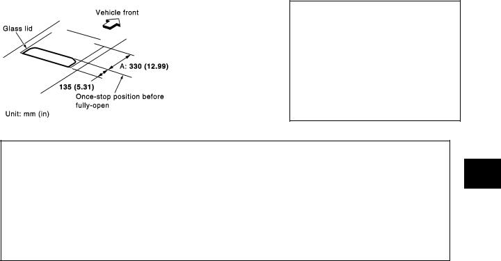
●Operating sunroof switch allows glass lid open/close, and tilt UP and DOWN.
●When sunroof switch is pressed firmly toward the OPEN side, glass lid automatically opens and automatic operation is stopped at a point 135 mm (5.31 in) to the fully closed position.
NOTE:
After the emergency handle is used to rotate the motor drive shaft, sunroof switch operation may not correspond to actual glass lid movement. When this happens, conduct resuming operation to restore normal operation.
A
B
C
RESUMING OPERATION
●If actual glass lid operation does not correspond to expected operation, operate sunroof switch to slide glass lid toward area A in the figure. This should result in resumption of normal operation.
CAUTION:
Before normal operation is resumed, expected sunroof switch operation and actual glass lid movement may not correspond. Make sure that neither head nor hands protrude from sunroof and conduct resuming operation.
D
E
F
G
MIIA0058E
Component Parts Location
EIS004NO
MIIB0916E
H
RF
J
K
L
M
RF-7
SUNROOF
[Sunroof]
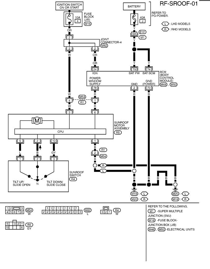
Wiring Diagram — SROOF — |
EIS004NP |
MIWA0423E
RF-8

SUNROOF
|
|
|
|
|
[Sunroof] |
||
Terminal and Reference Value for Sunroof Switch |
EIS004NQ |
||||||
|
|
|
|
|
|
|
|
|
TERMI- |
WIRE |
ITEM |
CONDITION |
VOLTAGE(V) |
||
|
NAL |
COLOR |
(Approx.) |
||||
|
|
|
|||||
|
|
|
|
|
|
|
|
1 |
L |
Sunroof tilt UP or OPEN signal |
Sunroof switch tilt UP or OPEN operation |
0 → Battery voltage |
|||
|
|
|
|
|
|
|
|
2 |
B |
IGN power supply |
— |
Battery voltage |
|||
|
|
|
|
|
|
|
|
3 |
GY |
Sunroof tilt DOWN or CLOSE sig- |
Sunroof switch tilt DOWN or CLOSE |
0 →Battery voltage |
|||
nal |
operation |
||||||
|
|
|
|
|
|||
|
|
|
|
|
|
|
|
Sunroof Lid Weatherstrip Inspection |
|
EIS004NR |
|||||
If there is water leakage around glass lid, close glass lid and flush with water to determine whether it is from damaged parts or a gap.
1.Remove glass lid assembly.
2.Visually check weatherstrip for damage, deterioration, or deformation. If excess wear or damage is detected, replace glass lid assembly.
Link and Wire Assembly Inspection |
EIS004NS |
1.If the link coating peels off to show the base material and an abnormal noise is heard, replace it.
2.Visually confirm the wire and rail groove are properly greased. If necessary, apply body grease.
A
B
C
D
E
F
Fitting Adjustment |
EIS004NT |
MIIA0048E
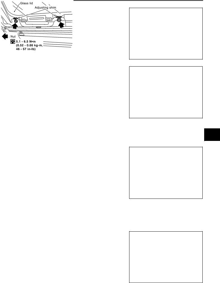
LONGITUDINAL/LATERAL CLEARANCE ADJUSTMENT
1.Tilt up glass lid to remove side trim upper and lower.
2.After loosening glass lid mounting bolts (Torx bolt: T25, 3 each on left/right), tilt down glass lid.
3.Adjust glass lid according to sections A–A, B–B, C–C as shown in the figure.
4.After adjusting glass lid, tighten nuts to the specified torque.
5.Tilt glass lid 4 to 5 times to check that it smoothly goes up and down.
G
H
RF
J
K
L
M
RF-9

SUNROOF
[Sunroof]
SURFACE MISMATCH ADJUSTMENT
1.Adjust surface height of glass lid and roof panel to 0±1.5 mm (0±0.059 in) by altering the number of shims between glass lid and link assembly. (Standard: 2, max: 4)
2.After fitting adjustment, use a hose to flush the entire surface of the roof with water to check for leaks.
MIIB0015E
RF-10
SUNROOF
[Sunroof]
Removal and Installation |
EIS004NU |
A
B
C
D
E
F
G
H
RF
J
K
L
M
MIIB0998E
RF-11
SUNROOF
[Sunroof]
SUNROOF UNIT
Removal
CAUTION:
●Removal and installation of sunroof unit must be performed by 2 persons.
●When taking sunroof unit out, use shop cloths to protect seats and trim from damage.
●After installing sunroof unit and glass lid, be sure to carry out the leak test to confirm there is no more leakage.
1.Remove headlining. Refer to EI-33, "HEADLINER" .
2.Disconnect drain hoses (4).
3.Disconnect interior lamp harness.
4.Remove sunroof map lamp bracket mounting bolt.
5.Remove sunroof motor assembly.
MIIB0999E
6.Remove both unit-side and body-side front sunroof bracket mounting bolts and nuts.
7.Remove both unit-side and body-side rear sunroof bracket mounting bolts.
MIIB0011E
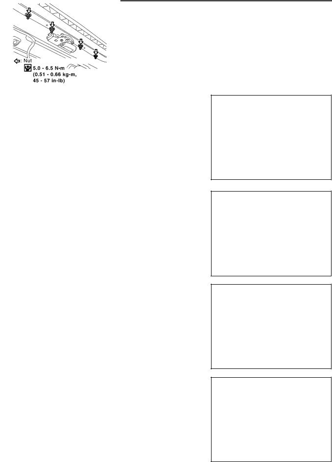
8.Remove mounting nuts on the front end.
MIIB0012E
9.Remove mounting nuts on the side rails, and remove sunroof unit from the roof panel.
10.Remove the sunroof unit out of the passenger compartment while being careful not to damage the seats and trim.
MIIB0013E
RF-12
SUNROOF
Installation
1.After bringing sunroof unit into the passenger compartment, tighten mounting nuts on the side rails (2 each on left/right). Start from the one at the front reference point.
2.Tighten mounting nuts (4) on the front end.
3.Align the front sunroof bracket to lower face of the rail and roof side mounting face, and tighten bolts. Then tighten bolts on the roof side.
4.Align the center and rear sunroof brackets to lower face of the rail and roof side mounting face, and tighten bolts. Then tighten bolts on the roof side.
NOTE:
Install the sunroof bracket evenly so that the roof surface has no distortion.
5.Tighten bolts on motor bracket.
6.Connect the interior lamp harness.
GLASS LID
Removal
1.Tilt up glass lid.
2.Remove side trim.
3.Remove installation from glass lid.
4.Remove glass lid.
Installation
1.Tighten nuts on glass lid diagonally.
2.After installation, adjust the fit. Refer to RF-9, "Fitting Adjustment" .
SUNROOF MOTOR
Removal
1.Remove motor mounting bolts (Torx bolt: T25).
2.Remove the harness connector, and remove the sunroof motor.
NOTE:
●Remove the sunroof motor when the sunroof is in the fullyclosed position.
●Never rotate the removed motor as a single unit.
[Sunroof]
A
B
C
D
SIIA0122E
E
F
G
MIIB0014E
H
RF
J
K
L
MIIB0015E M
MIIB0016E
RF-13

SUNROOF
[Sunroof]
Installation
1.Move motor laterally little by little until the gear is completely engaged onto the wire on sunroof unit and the mounting surface becomes parallel. Then secure motor with screws and nuts.
2.Connect harness connector to motor, and perform initial operation for initialization.
●To initialize, hold Tilt UP switch for approximately 10 seconds with sunroof tilted up. If this is not properly done, Tilt DOWN operation will not be performed normally.
3.After installation, check that sunroof operates normally.
NOTE:
Before installing motor, be sure to place the link and wire assembly in the symmetrical and fully closed position.
RF-14

|
PRECAUTIONS |
|
[Retractable Hard Top (C-View)] |
|
|
PRECAUTIONS |
PFP:00001 |
Precautions for Supplemental Restraint System (SRS) “AIR BAG” and “SEAT |
|
BELT PRE-TENSIONER” |
EIS00E7W |
The Supplemental Restraint System such as “AIR BAG” and “SEAT BELT PRE-TENSIONER”, used along with a front seat belt, helps to reduce the risk or severity of injury to the driver and front passenger for certain types of collision. Information necessary to service the system safely is included in the SRS and SB section of this Service Manual.
WARNING:
●To avoid rendering the SRS inoperative, which could increase the risk of personal injury or death in the event of a collision which would result in air bag inflation, all maintenance must be per-
formed by an authorized NISSAN/INFINITI dealer.
●Improper maintenance, including incorrect removal and installation of the SRS, can lead to per-
sonal injury caused by unintentional activation of the system. For removal of Spiral Cable and Air Bag Module, see the SRS section.
●Do not use electrical test equipment on any circuit related to the SRS unless instructed to in this Service Manual. SRS wiring harnesses can be identified by yellow and/or orange harnesses or
harness connectors.
Precautions for Hydraulic System |
EIS00E7X |
CAUTION:
●Do not bend or twist hydraulic hoses sharply, or strongly pull them.
●Note the identification number, location and routing of each hose before removal.
● After installation, hydraulic hoses must not move towards self-locking bands.
● Bleed the hydraulic circuit and check the hydraulic fluid level after any operation on the hydraulic system.
● While removing tubes, hydraulic fluid may spray out strongly. Protect the vehicle interior and luggage compartment with suitable covers.
● Do not allow a hydraulic tube disconnected. Prepare the new hydraulic component for quick replacement.
● Do not manipulate any hydraulic component or moving parts on the retractable hard top assembly while hydraulic tube are disconnected.
● Do not let any dirt entering in the hydraulic circuit.
●Serviceable parts for hydraulic circuit are not various. Before disassembly refer to RF-203, "Component Parts Drawing" .
WARNING:
●The retractable hard top may fall suddenly. Avoid working on the vehicle with hydraulic circuit under pressure. Always depressurize the system before starting. To depressurize the system, disconnect both battery cables starting by negative terminal.
●Do not allow hydraulic fluid to come in contact with skin, eyes, fabrics, or.
●After touching hydraulic fluid, do not touch or rub your eyes until you have thoroughly washed your hands.
–If hydraulic fluid contacts cloths, change them immediately.
–If hydraulic fluid contacts skin, wash skin with soap and water.
–If hydraulic fluid contacts eyes, immediately flush with water for 15 minutes and seek medical attention.
Precautions |
EIS00E7Y |
Disconnect both battery cables in advance starting with the negative terminal.
●When removing or disassembling any part, be careful not to damage or deform it. Protect parts, which may get in the way with cloth.
●When removing parts with a screwdriver or other tool, protect parts by wrapping them with vinyl or tape.
●Keep removed parts protected with cloth.
●If a clip is deformed or damaged, replace it.
●If an unreusable part is removed, replace it with a new one.
A
B
C
D
E
F
G
H
RF
J
K
L
M
RF-15

PRECAUTIONS
[Retractable Hard Top (C-View)]
●Tighten bolts and nuts firmly to the specified torque.
●After re-assembly has been completed, make sure each part functions correctly.
●Remove stains in the following way.
Water-soluble stains:
Dip a soft cloth in warm water, and then squeeze it tightly. After wiping the stain, wipe with a soft dry cloth. Oil stain:
Dissolve a synthetic detergent in warm water (density of 2 to 3% or less), dip the cloth, then clean off the stain with the cloth. Next, dip the cloth in fresh water and squeeze it tightly. Then clean off the detergent completely. Then wipe the area with a soft dry cloth.
●Do not use any organic solvent, such as thinner or benzine.
RF-16
PREPARATION |
[Retractable Hard Top (C-View)] |
|
|
|
|
|
|
|
|
|
|
PREPARATION |
PFP:00002 |
|
A |
Special Service Tools |
|
|
|
EIS00DZD |
|
|
|
|
|
|
|
Tool name |
Description |
|
B |
|
|
|
|
|
|
|
|
Chassis ear |
Locating the noise |
|
C |
|
|
||
SIIA0993E |
|
|
D |
|
|
|
E |
NISSAN Squeak and Rattle |
|
|
|
Repairing the cause of noise |
|
|
|
Kit |
|
|
|
|
|
|
|
|
|
|
F |
SIIA0994E |
|
|
|
|
|
|
|
Commercial Service Tools |
EIS00DZE |
|
G |
|
|
|
|
Tool name |
Description |
|
|
|
|
|
H |
|
|
|
|
Engine ear |
Locating the noise |
|
|
|
RF |
||
|
|
|
|
SIIA0995E |
|
|
|
|
|
|
|
|
|
|
J |
|
|
|
|
|
|
|
K |
|
|
|
L |
|
|
|
M |
RF-17

SQUEAK AND RATTLE TROUBLE DIAGNOSES
|
[Retractable Hard Top (C-View)] |
SQUEAK AND RATTLE TROUBLE DIAGNOSES |
PFP:00000 |
Work Flow |
EIS00E7J |
SBT842
CUSTOMER INTERVIEW
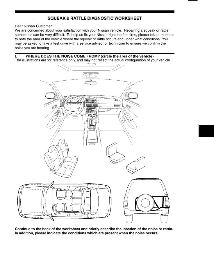
Interview the customer if possible, to determine the conditions that exist when the noise occurs. Use the Diagnostic Worksheet during the interview to document the facts and conditions when the noise occurs and any customer's comments; refer to RF-23, "Diagnostic Worksheet" . This information is necessary to duplicate the conditions that exist when the noise occurs.
●The customer may not be able to provide a detailed description or the location of the noise. Attempt to obtain all the facts and conditions that exist when the noise occurs (or does not occur).
●If there is more than one noise in the vehicle, be sure to diagnose and repair the noise that the customer is concerned about. This can be accomplished by test driving the vehicle with the customer.
●After identifying the type of noise, isolate the noise in terms of its characteristics. The noise characteristics are provided so the customer, service adviser and technician are all speaking the same language when defining the noise.
●Squeak —(Like tennis shoes on a clean floor)
Squeak characteristics include the light contact/fast movement/brought on by road conditions/hard surfaces=higher pitch noise/softer surfaces=lower pitch noises/edge to surface=chirping
●Creak—(Like walking on an old wooden floor)
Creak characteristics include firm contact/slow movement/twisting with a rotational movement/pitch dependent on materials/often brought on by activity.
●Rattle—(Like shaking a baby rattle)
Rattle characteristics include the fast repeated contact/vibration or similar movement/loose parts/missing clip or fastener/incorrect clearance.
●Knock —(Like a knock on a door)
Knock characteristics include hollow sounding/sometimes repeating/often brought on by driver action.
●Tick—(Like a clock second hand)
Tick characteristics include gentle contacting of light materials/loose components/can be caused by driver action or road conditions.
●Thump—(Heavy, muffled knock noise)
Thump characteristics include softer knock/dead sound often brought on by activity.
●Buzz—(Like a bumble bee)
Buzz characteristics include high frequency rattle/firm contact.
●Often the degree of acceptable noise level will vary depending upon the person. A noise that you may judge as acceptable may be very irritating to the customer.
●Weather conditions, especially humidity and temperature, may have a great effect on noise level.
RF-18

SQUEAK AND RATTLE TROUBLE DIAGNOSES
[Retractable Hard Top (C-View)]
DUPLICATE THE NOISE AND TEST DRIVE
If possible, drive the vehicle with the customer until the noise is duplicated. Note any additional information on the Diagnostic Worksheet regarding the conditions or location of the noise. This information can be used to duplicate the same conditions when you confirm the repair.
If the noise can be duplicated easily during the test drive, to help identify the source of the noise, try to duplicate the noise with the vehicle stopped by doing one or all of the following:
1)Close a door.
2)Tap or push/pull around the area where the noise appears to be coming from.
3)Rev the engine.
4)Use a floor jack to recreate vehicle “twist”.
5)At idle, apply engine load (electrical load, half-clutch on M/T model, drive position on A/T model).
6) Raise the vehicle on a hoist and hit a tire with a rubber hammer.
●Drive the vehicle and attempt to duplicate the conditions the customer states exist when the noise occurs.
●If it is difficult to duplicate the noise, drive the vehicle slowly on an undulating or rough road to stress the
vehicle body.
CHECK RELATED SERVICE BULLETINS
After verifying the customer concern or symptom, check ASIST for Technical Service Bulletins (TSBs) related to that concern or symptom.
If a TSB relates to the symptom, follow the procedure to repair the noise.
A
B
C
D
E
F
LOCATE THE NOISE AND IDENTIFY THE ROOT CAUSE
1.Narrow down the noise to a general area. To help pinpoint the source of the noise, use a listening tool (Engine Ear or mechanics stethoscope).
2.Narrow down the noise to a more specific area and identify the cause of the noise by:
●removing the components in the area that you suspect the noise is coming from.
Do not use too much force when removing clips and fasteners, otherwise clips and fastener can be broken or lost during the repair, resulting in the creation of new noise.
●tapping or pushing/pulling the component that you suspect is causing the noise.
Do not tap or push/pull the component with excessive force, otherwise the noise will be eliminated only temporarily.
● feeling for a vibration with your hand by touching the component(s) that you suspect is (are) causing the noise.
● placing a piece of paper between components that you suspect are causing the noise.
● looking for loose components and contact marks.
Refer to RF-20, "Generic Squeak and Rattle Troubleshooting" .
G
H
RF
J
K
REPAIR THE CAUSE
●If the cause is a loose component, tighten the component securely.
●If the cause is insufficient clearance between components:
–separate components by repositioning or loosening and retightening the component, if possible.
–insulate components with a suitable insulator such as urethane pads, foam blocks, felt cloth tape or urethane tape are available through your authorized Nissan Parts Department.
CAUTION:
Do not use excessive force as many components are constructed of plastic and may be damaged.
NOTE:
Always check with the Parts Department for the latest parts information. Each item can be ordered separately as needed.
URETHANE PADS [1.5 mm (0.059 in) thick] Insulates connectors, harness, etc.
76268-9E005: 100 × 135 mm (3.94 × 5.31 in)/76884-71L01: 60 × 85 mm (2.36 × 3.35 in)/76884-71L02: 15 × 25 mm (0.59 × 0.98 in)
INSULATOR (Foam blocks)
Insulates components from contact. Can be used to fill space behind a panel.
73982-9E000: 45 mm (1.77 in) thick, 50 × 50 mm (1.97 × 1.97 in)/73982-50Y00: 10 mm (0.39 in) think, 50 × 50 mm (1.97 × 1.97 in)
INSULATOR (Light foam block)
80845-71L00: 30 mm (1.18 in) thick, 30 × 50 mm (1.18 × 1.97 in)
L
M
RF-19

SQUEAK AND RATTLE TROUBLE DIAGNOSES
[Retractable Hard Top (C-View)]
FELT CLOTHTAPE
Used to insulate where movement does not occur. Ideal for instrument panel applications. 68370-4B000: 15 × 25 mm (0.59 × 0.98 in) pad/68239-13E00: 5 mm (0.20 in) wide tape roll
The following materials, not available through NISSAN Parts Department, can also be used to repair squeaks and rattles.
UHMW(TEFLON) TAPE
Insulates where slight movement is present. Ideal for instrument panel applications. SILICONE GREASE
Used in place of UHMW tape that will be visible or not fit. Note: Will only last a few months.
SILICONE SPRAY
Use when grease cannot be applied. DUCT TAPE
Use to eliminate movement.
CONFIRM THE REPAIR
Confirm that the cause of a noise is repaired by test driving the vehicle. Operate the vehicle under the same conditions as when the noise originally occurred. Refer to the notes on the Diagnostic Worksheet.
Generic Squeak and Rattle Troubleshooting |
EIS00E7K |
Refer to Table of Contents for specific component removal and installation information.
INSTRUMENT PANEL
Most incidents are caused by contact and movement between:
1.Cluster lid A and instrument panel
2.Acrylic lens and combination meter housing
3.Instrument panel to front pillar garnish
4.Instrument panel to windshield
5.Instrument panel mounting pins
6.Wiring harnesses behind the combination meter
7.A/C defroster duct and duct joint
These incidents can usually be located by tapping or moving the components to duplicate the noise or by pressing on the components while driving to stop the noise. Most of these incidents can be repaired by applying felt cloth tape or silicon spray (in hard to reach areas). Urethane pads can be used to insulate wiring harness.
CAUTION:
Do not use silicone spray to isolate a squeak or rattle. If you saturate the area with silicone, you will not be able to recheck the repair.
CENTER CONSOLE
Components to pay attention to include:
1.Shifter assembly cover to finisher
2.A/C control unit and cluster lid C
3.Wiring harnesses behind audio and A/C control unit
The instrument panel repair and isolation procedures also apply to the center console.
DOORS
Pay attention to the:
1.Finisher and inner panel making a slapping noise
2.Inside handle escutcheon to door finisher
3.Wiring harnesses tapping
4.Door striker out of alignment causing a popping noise on starts and stops
Tapping or moving the components or pressing on them while driving to duplicate the conditions can isolate many of these incidents. You can usually insulate the areas with felt cloth tape or insulator foam blocks to repair the noise.
RF-20
SQUEAK AND RATTLE TROUBLE DIAGNOSES
[Retractable Hard Top (C-View)]
TRUNK
Trunk noises are often caused by a loose jack or loose items put into the trunk by the owner. |
A |
In addition look for: |
|
1.Trunk lid dumpers out of adjustment
2. |
Trunk lid striker out of adjustment |
B |
|
||
3. |
Trunk lid torsion bars knocking together |
|
4. |
A loose license plate or bracket |
|
C
Most of these incidents can be repaired by adjusting, securing or insulating the item(s) or component(s) causing the noise.
SUNROOF/HEADLINING
Noises in the sunroof/headlining area can often be traced to one of the following:
1.Sunroof lid, rail, linkage or seals making a rattle or light knocking noise
2.Sunvisor shaft shaking in the holder
3.Front or rear windshield touching headlining and squeaking
Again, pressing on the components to stop the noise while duplicating the conditions can isolate most of these incidents. Repairs usually consist of insulating with felt cloth tape.
SEATS
When isolating seat noise it's important to note the position the seat is in and the load placed on the seat when the noise is present. These conditions should be duplicated when verifying and isolating the cause of the noise.
Cause of seat noise include:
1.Headrest rods and holder
2.A squeak between the seat pad cushion and frame
3.Rear seatback lock and bracket
These noises can be isolated by moving or pressing on the suspected components while duplicating the conditions under which the noise occurs. Most of these incidents can be repaired by repositioning the component or applying urethane tape to the contact area.
UNDERHOOD
Some interior noise may be caused by components under the hood or on the engine wall. The noise is then transmitted into the passenger compartment.
Causes of transmitted underhood noise include:
1.Any component mounted to the engine wall
2.Components that pass through the engine wall
3.Engine wall mounts and connectors
4.Loose radiator mounting pins
5.Hood bumpers out of adjustment
6.Hood striker out of adjustment
These noises can be difficult to isolate since they cannot be reached from the interior of the vehicle. The best method is to secure, move or insulate one component at a time and test drive the vehicle. Also, engine RPM or load can be changed to isolate the noise. Repairs can usually be made by moving, adjusting, securing, or insulating the component causing the noise.
RETRACTABLE HARD TOP
Rattle noises can occure in open or close positions.
In open position rattle noises are often caused by:
1.Bad adjustment of roof stop bumpers
2.Bad adjustment of link stop bampers
3.Absence of rubber bumper on trunk lid
In closed position rattle noises are often caused by:
1.Bad routing of hydraulic lines
2.Incorrect installation of headlining
D
E
F
G
H
RF
J
K
L
M
RF-21

SQUEAK AND RATTLE TROUBLE DIAGNOSES
[Retractable Hard Top (C-View)]
3.Looseness of component in sunshade assembly
RF-22
SQUEAK AND RATTLE TROUBLE DIAGNOSES
[Retractable Hard Top (C-View)]
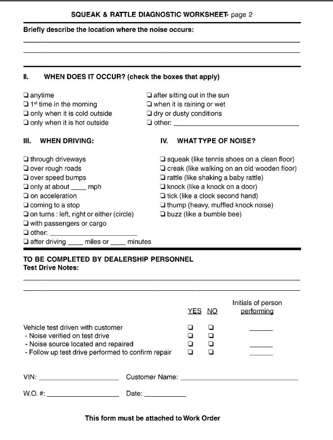
Diagnostic Worksheet |
EIS00E7L |
A
B
C
D
E
F
G
H
RF
J
K
L
M
PIIB0723E
RF-23
SQUEAK AND RATTLE TROUBLE DIAGNOSES
[Retractable Hard Top (C-View)]
SBT844
RF-24
|
CLIP AND FASTENER |
||
|
[Retractable Hard Top (C-View)] |
||
|
|
|
|
CLIP AND FASTENER |
PFP:76906 |
||
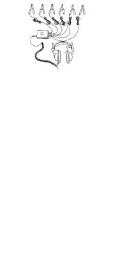
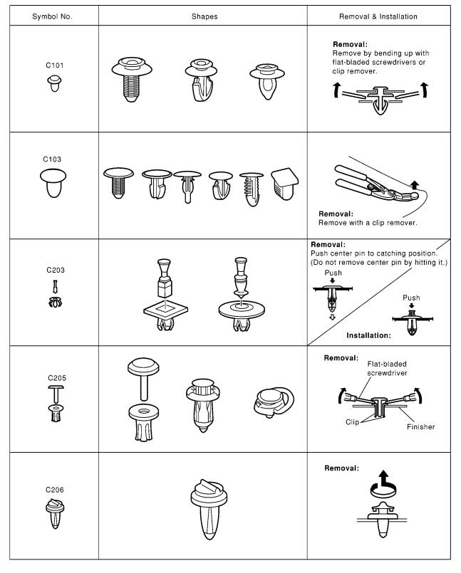
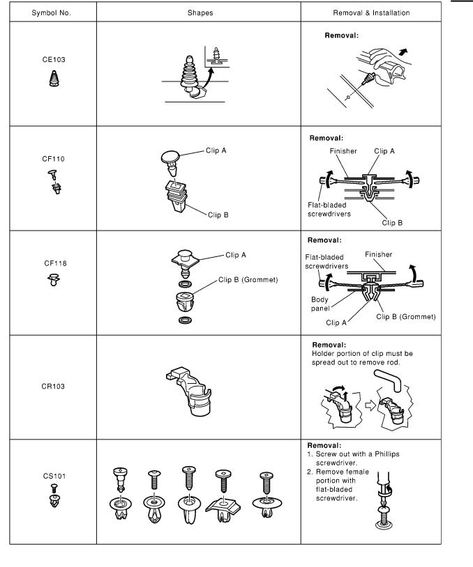
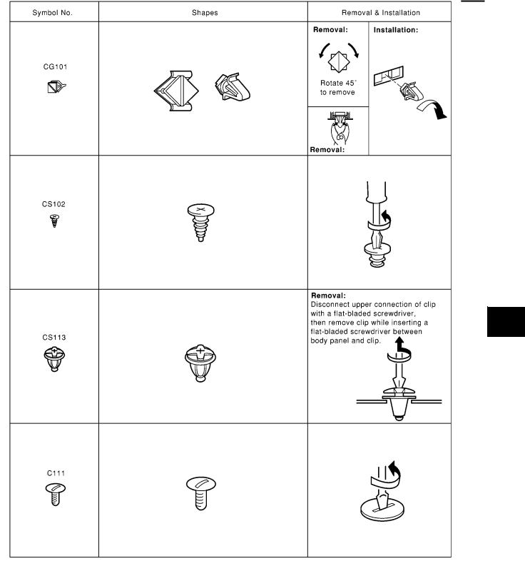
Clip and Fastener |
|
|
A |
EIS00E7S |
|||
|
|
|
B |
|
|
|
C |
|
|
|
D |
|
|
|
E |
|
|
|
F |
|
|
|
G |
|
|
|
H |
|
|
|
|
|
|
|
RF |
|
|
|
|
|
|
|
J |
|
|
|
K |
|
|
|
L |
|
|
|
M |
SIIA0315E
RF-25
CLIP AND FASTENER
[Retractable Hard Top (C-View)]
SIIA0316E
RF-26
CLIP AND FASTENER
[Retractable Hard Top (C-View)]
A
B
C
D
E
F
G
H
RF
J
K
L
M
SIIA0317E
RF-27

TROUBLE DIAGNOSIS
[Retractable Hard Top (C-View)]
TROUBLE DIAGNOSIS
Component Parts and Harness Connector Location
PFP:00004
EIS00DZF
MIIB1166E
RF-28

TROUBLE DIAGNOSIS
[Retractable Hard Top (C-View)]
A
B
C
D
E
F
G
H
RF
J
K
L
M
|
|
MIIB1167E |
1. Fuse block (F/B) fuse layout |
2. Fuse and fusible link box |
3. BCM (View with upper instrument |
|
|
panel) M48, M49, M50 |
4.View with trunk lid finisher LH removed
A.Hydraulic unit B77, B78
B.Retractable hard top control unit B82, B83, B84
5.A. Hydraulic valve B405
B.Hydraulic relay RL B404
C.Hydraulic relay LL B403
6. Retractable hard top warning lamp (Combination meter) M22
7. |
Front power window motor RH |
8. |
Rear power window motor RH B67 |
9. |
Trunk lid side latch RH T5 |
|
LHD: D35 RHD: D5 |
|
|
|
|
10. |
A. Hall sensor B75 |
11. |
Roof limit switch (OPEN) B74 |
12. |
Trunk lid switch (Trunk lid release |
|
B. Trunk lid side latch T6 |
|
|
|
actuator) B55 |
13. |
Roof limit switch (LOCK) R7 |
14. |
Roof limit switch (CLOSE) R10 |
15. |
Roof storage switch B79, B80 |
16. |
Parcel shelf |
17. |
Roof open/close switch B66 |
|
|
A.Parcel shelf limit switch (CLOSE)
B.Parcel shelf limit switch (OPEN)
C.Parcel shelf motor
RF-29

TROUBLE DIAGNOSIS
[Retractable Hard Top (C-View)]
System Description |
EIS00DZG |
SYSTEM DIAGRAM
MIIB1071E
RF-30
Loading...