


Micra 2005
Table of contents
 Loading...
BRAKE SYSTEM
F BRAKES
A
B
SECTION BR
CONTENTS
PRECAUTIONS .......................................................... 3
Precautions for Supplemental Restraint System
(SRS)“AIRBAG”and“SEATBELTPRE-TEN-
SIONER” .................................................................. 3
PrecautionsforProcedureswithoutCowlTopCover..... 3
Precautions for Brake System .................................. 3
PREPARATION ........................................................... 4
Special Service Tools ............................................... 4
NOISE, VIBRATION AND HARSHNESS (NVH)
TROUBLESHOOTING ................................................ 5
NVH Troubleshooting Chart ..................................... 5
BRAKE PEDAL .......................................................... 6
Inspection and Adjustment ....................................... 6
PLAY AND CLEARANCE BETWEEN BRAKE
PEDAL AND FLOOR PANEL WITH PEDAL
DEPRESSED. ....................................................... 6
Removal and Installation .......................................... 7
COMPONENTS .................................................... 7
REMOVAL ............................................................. 7
INSPECTION AFTER REMOVAL ......................... 8
INSTALLATION ..................................................... 8
BRAKE FLUID ............................................................ 9
Level Inspection ....................................................... 9
Checking Brake Line ................................................ 9
Drain and Refill ......................................................... 9
Bleeding Brake System .......................................... 10
BRAKE PIPING AND HOSE .....................................11
Hydraulic Circuit ......................................................11
RemovalandInstallationofFrontBrakePipingand
Brake Hose .............................................................11
REMOVAL ............................................................11
INSTALLATION ................................................... 12
Removaland Installationof RearBrakePipingand
Brake Hose ............................................................ 12
REMOVAL ........................................................... 12
INSTALLATION ................................................... 12
Inspection ............................................................... 13
BRAKE MASTER CYLINDER .................................. 14
BRAKE SYSTEM
Removal and Installation ........................................ 14
REMOVAL ...........................................................14
INSTALLATION ................................................... 14
Disassembly and Assembly .................................... 14
DISASSEMBLY ................................................... 15
INSPECTION AFTER DISASSEMBLY ............... 15
ASSEMBLY ......................................................... 15
BRAKE BOOSTER ...................................................17
On-Vehicle Service .................................................17
OPERATING CHECK ..........................................17
AIRTIGHTNESS INSPECTION ...........................17
Removal and Installation ........................................ 17
COMPONENTS ...................................................17
REMOVAL ...........................................................17
INSTALLATION ................................................... 18
VACUUM LINES ....................................................... 19
Components ...........................................................19
Removal and Installation ........................................ 19
VACUUM HOSE .................................................. 19
VACUUM PUMP .................................................. 19
Inspection ...............................................................20
VISUAL INSPECTION .........................................20
CHECK VALVE INSPECTION ............................. 20
FRONT DISC BRAKE ............................................... 21
On Board Inspection ............................................... 21
PAD WEAR INSPECTION ................................... 21
Components ...........................................................21
Removal and Installation of Brake Pad .................. 22
REMOVAL ...........................................................22
INSTALLATION ................................................... 22
RemovalandInstallationofBrakeCaliperAssembly
...23
REMOVAL ...........................................................23
INSTALLATION ................................................... 23
Disassembly and Assembly of Brake Caliper
Assembly ................................................................ 23
DISASSEMBLY ................................................... 23
BRAKE CALIPER INSPECTION ......................... 24
C
D
E
BR
G
H
I
J
K
L
M
BR-1

ASSEMBLY .........................................................24
Removal and Installation of Disc Rotor ...................25
REMOVAL ...........................................................25
INSTALLATION ....................................................25
DISC ROTOR INSPECTION ...............................25
BRAKE BURNISHING PROCEDURE .................26
REAR DRUM BRAKE ............................................... 27
Components ........................................................... 27
RemovalandInstallation ofDrum BrakeAssembly...28
REMOVAL ...........................................................28
INSPECTION AFTER REMOVAL ........................ 28
INSTALLATION ....................................................29
Removal and Installation of Wheel Cylinder ...........30
REMOVAL ............................................................30
INSTALLATION ....................................................30
Disassembly and Assembly of Wheel Cylinder .......30
DISASSEMBLY ....................................................30
ASSEMBLY ..........................................................30
Wheel Cylinder Inspection ......................................31
SERVICE DATA AND SPECIFICATIONS (SDS) ......32
General Specifications ............................................32
Brake Pedal ............................................................32
Brake Booster .........................................................32
Check Valve ............................................................32
Front Disc Brake .....................................................33
Rear Drum Brake ....................................................33
BR-2

PRECAUTIONS
PRECAUTIONS PFP:00001
Precautions for Supplemental Restraint System (SRS) “AIR BAG” and “SEAT BELT PRE-TENSIONER”
EFS002FV
A
The Supplemental Restraint System such as “AIR BAG” and “SEAT BELT PRE-TENSIONER”, used along
with a front seat belt, helps to reduce the risk or severity of injury to the driver and front passenger for certain
types of collision. This system includes seat belt switch inputs and dual stage front air bag modules. The SRS
system uses the seat belt switches to determine the front air bag deployment, and may only deploy one front
air bag, depending on the severity of a collision and whether the front occupants are belted or unbelted.
Informationnecessary to service the system safely is included in the SRS and SB section of this Service Manual.
WARNING:
● To avoid rendering the SRS inoperative, which could increase the risk of personal injury or death
in the event of a collision which would result in air bag inflation, all maintenance must be performed by an authorized NISSAN/INFINITI dealer.
● Improper maintenance, including incorrect removal and installation of the SRS, can lead to per-
sonal injury caused by unintentional activation of the system. For removal of Spiral Cable and Air
Bag Module, see the SRS section.
● Do not use electrical test equipment on any circuit related to the SRS unless instructed to in this
Service Manual. SRS wiring harnesses can be identified by yellow and/or orange harnesses or
harness connectors.
Precautions for Procedures without Cowl Top Cover
EFS006DI
When performingthe procedure after removingcowl top cover,cover
the lower end of windshield with urethane, etc.
B
C
D
E
BR
G
H
I
PIIB3706J
Precautions for Brake System
● Clean dust on front brake and rear brake with a vacuum dust collector. Do not blow with compressed air.
● Recommended fluid is brake fluid “DOT 3” or “DOT 4”.
● Never reuse drained brake fluid.
● Be careful not to splash brake fluid on painted areas; it may cause paint damage. If brake fluid is splashed
EFS002FW
on painted areas, wash it away with water immediately.
● To clean or wash all parts of master cylinder, disc brake caliper and wheel cylinder, use new brake fluid.
● Never use mineral oils such as gasoline or kerosene. They will ruin rubber parts of the hydraulic system.
● Use a flare nut wrench when removing flare nuts, and use a flare
nut torque wrench when tightening flare nuts.
● Always tighten brake lines to the specified torque when install-
ing.
● Before working, turn ignition switch OFF and disconnect electri-
cal connector of ABS actuator and electric unit (control unit) or
the battery cables.
● Burnish the brake contact surfaces after refinishing or replacing
drums or rotors, after replacing pads or linings, or if a soft pedal
occurs at very low mileage.
Refer to BR-26, "
BRAKE BURNISHING PROCEDURE" .
SBR820BA
J
K
L
M
BR-3
PREPARATION
PREPARATION
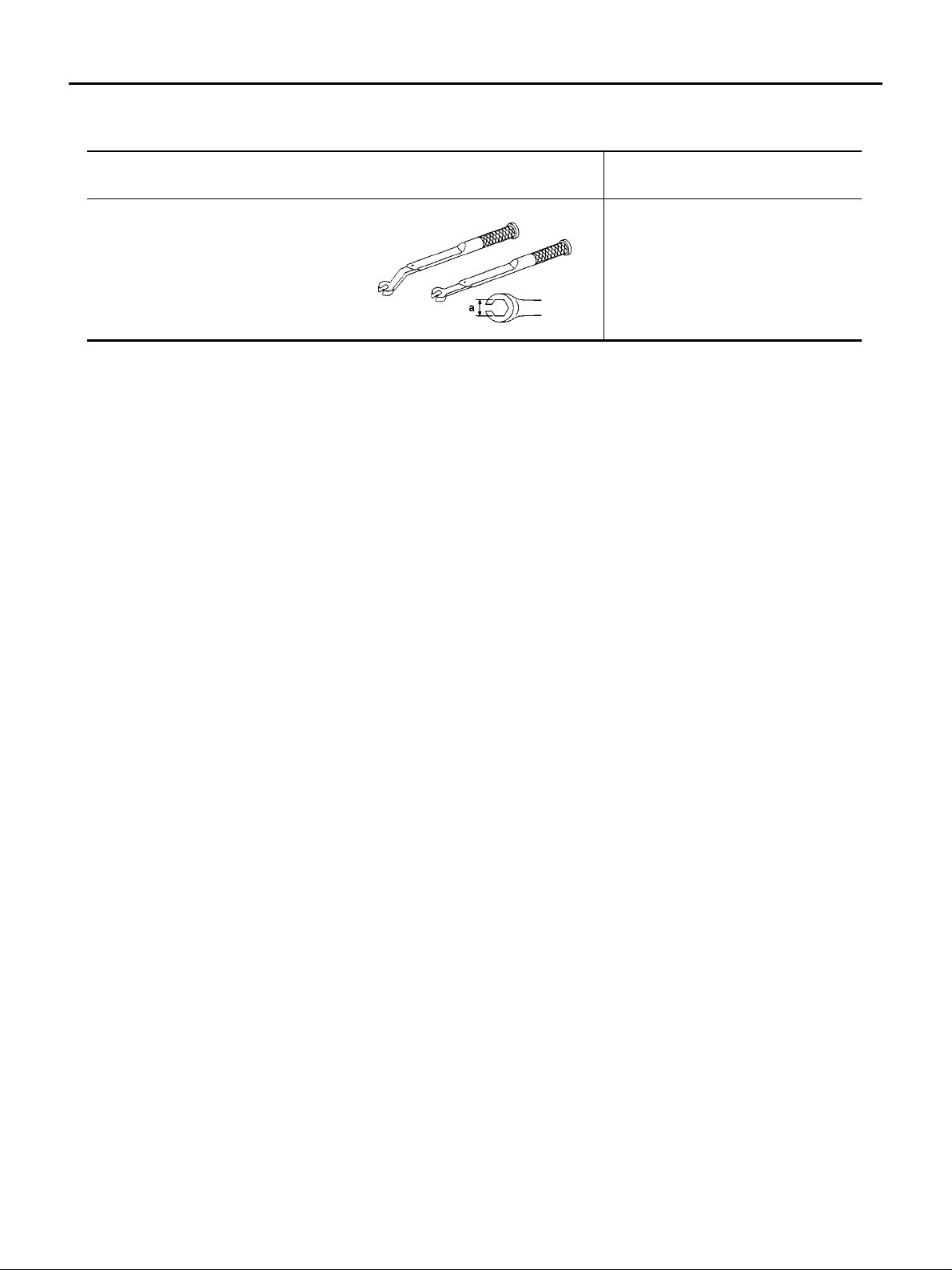
Special Service Tools
Tool number
Tool name
GG94310000
Flare nut torquewrench
a: 10 mm (0.39 in)
PFP:00002
EFS002G1
Description
Removing and installing each brake
piping
NT406
BR-4
NOISE, VIBRATION AND HARSHNESS (NVH) TROUBLESHOOTING
NOISE, VIBRATION AND HARSHNESS (NVH) TROUBLESHOOTING PFP:00003
NVH Troubleshooting Chart
Use the chart below to help you find the cause of the symptom. If necessary, repair or replace these parts.
EFS002IV
A
B
C
Reference page
Possible cause and
SUSPECTED PARTS
Symptom BRAKE
X: Applicable
—
, BR-29
BR-25
—
—
BR-25
—
BR-26
D
—
BR-21, BR-28
BR-21, BR-28
E
NVH in FAX, RAX and FSU, RSU section
NVH in WT section
NVH in WT section
NVH in FAX section
NVH in PS section
BR
G
H
Pads or linings - damaged
Pads or linings - uneven wear
Return spring damaged
Rotorordrumimbalance
Rotorordrumdamage
Rotor runout
Rotorordrumdeformation
Rotorordrumdeflection
Rotorordrumrust
Rotor thickness variation
AXLE AND SUSPENSION
TYRES
ROAD WHEEL
DRIVESHAFT
STEERING
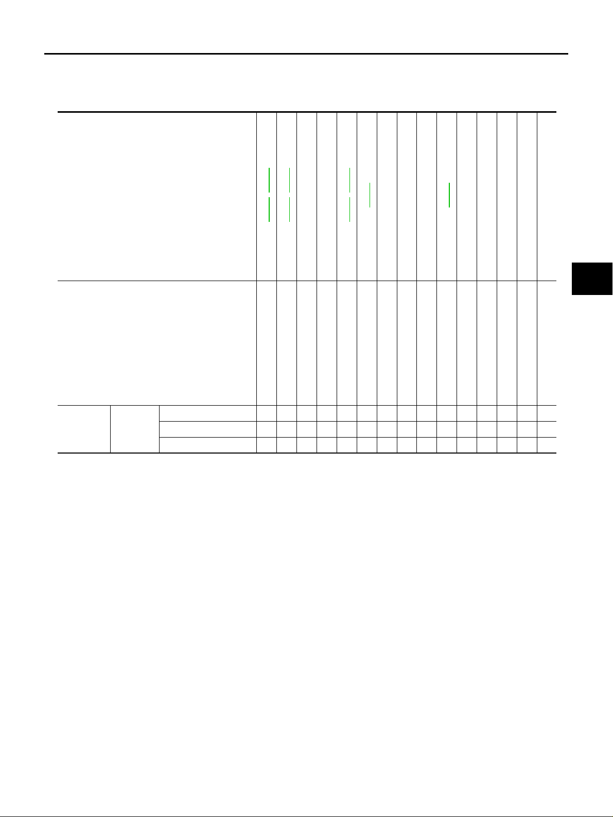
Noise ××× ×××
Shake ××××
Shimmy, Judder ЧЧЧЧЧЧЧЧЧЧ ×
×
×
×
×
I
J
K
BR-5
L
M

BRAKE PEDAL
BRAKE PEDAL
Inspection and Adjustment
PLAY AND CLEARANCE BETWEEN BRAKE PEDAL AND FLOOR PANEL WITH PEDAL DEPRESSED.
● Check the pedal play.
● Check the brake pedal free height from the dash floor panel.
● If value is outside the standard, make an adjustment to the fol-
lowing dimension.
PFP:46501
EFS002G6
SFIA1116E
LHD
H1 Brake pedal height
RHD
Depressed pedal height
H
2
[under a force of 490 N (50 kg, 110 lb) with the engine running]
C Clearance between the stopper rubber and the threaded end of stop lamp switch. 0.74 - 1.96 mm (0.029 - 0.077 in)
A Pedal play 3 - 11 mm (0.12 - 0.43 in)
M/T models 161 - 171 mm (6.34 - 6.73 in)
A/T models 171 - 181 mm (6.73 - 7.13 in)
M/T models 156 - 166 mm (6.14 - 6.54 in)
A/T models 166 - 176 mm (6.54 - 6.93 in)
M/T models 80 mm (3.15 in) or more
A/T models 85 mm (3.35 in) or more
BR-6

BRAKE PEDAL
Removal and Installation
EFS002G7
COMPONENTS
SFIA1114E
1. Snap pin 2. Stop lamp switch 3. Clip
4. Brake pedal assembly 5. Clevis pin
CAUTION:
● Be careful not to deform brake tube.
● Do not strike the brake pedal assembly against anything during removal and installation.
REMOVAL
1. Remove instrument lower driver panel. Refer to IP-4, "INSTRUMENT PANEL ASSEMBLY" .
2. Remove accelerator pedal harness clip and connector.
3. Disconnect stop lamp switch harness connector and remove stop lamp switch from the pedal assembly.
(Remove it by rotating the switch by 45°)
4. Remove snap pin and clevis pin from the brake booster clevis.
5. Remove pedal assembly mounting nut and then remove pedal assembly from the vehicle while moving
the master cylinder and brake booster to the engine room side while being careful not to deform the brake
tube.
6. Remove accelerator pedal from the brake pedal.
A
B
C
D
E
BR
G
H
I
J
K
L
BR-7
M
SFIA1115E

BRAKE PEDAL
INSPECTION AFTER REMOVAL
● Check brake pedal for bend, damage, and cracks on the welded parts. Replace applicable part if any non-
standard condition is detected.
INSTALLATION
● For information regarding the tightening torque, refer to BR-7, "COMPONENTS" . Install in the reverse
order of removal.
● After installing brake pedal assembly to the vehicle, adjust brake pedal.
BR-8

BRAKE FLUID
BRAKE FLUID PFP:KN100
Level Inspection
● Make sure the fluid level in the reservoir tank is within the stan-
dard (between MAX and MIN lines).
● Visually check around the reservoir tank for fluid leaks.
● If fluid level is excessively low, check brake system for leaks.
● If warning lamp remains illuminated after parking lever is
released, check brake system for fluid leakage.
Checking Brake Line
CAUTION:
If leakage occurs around joints, retighten or, if necessary, replace damaged parts.
1. Check brake line (tubes and hoses) for cracks, deterioration or
other damage. Replace any damaged parts.
2. Check for oil leakage by fully depressing brake pedal while
engine is running.
EFS002G8
SFIA0527J
EFS002G9
A
B
C
D
E
BR
G
SBR389C
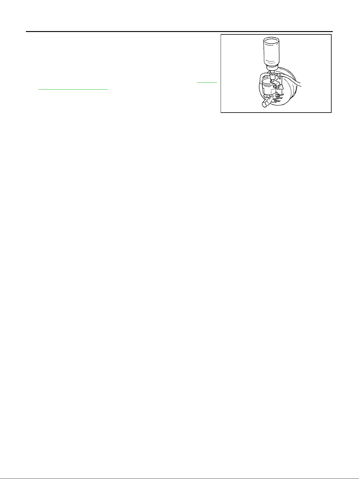
Drain and Refill
EFS002GA
CAUTION:
● Refill with new brake fluid “DOT 3” or “DOT 4”.
● Do not mix different types of brake fluid (DOT 3, DOT 4).
● Never reuse drained brake fluid.
● Be careful not to splash brake fluid on painted areas; it may cause paint damage. If brake fluid is
splashed on painted areas, wash it away with water immediately.
1. Turn ignition switch OFF, and remove ABS actuator connector.
2. Connect a vinyl tube to the air bleeder.
3. Drain brake fluid gradually from the air bleeder of each wheel
while depressing the brake pedal.
H
I
J
K
L
M
BR-9
BRA0007D
BRAKE FLUID
4. Make sure that there is no foreign material in the reservoir tank,
and refill with new brake fluid.
5. Rest foot on brake pedal. Loosen air bleeder. Slowly depress
pedal until it stops. Tighten air bleeder. Release brake pedal.
Repeat this process a few times, then pause to add new brake
fluid to master cylinder. Continue until new brake fluid flows out.
For information regarding air bleeding work, refer to BR-10,
"Bleeding Brake System" .
BRA0006D
Bleeding Brake System
EFS002GB
CAUTION:
● While bleeding, pay attention to master cylinder fluid level.
● Fill reservoir with new brake fluid “DOT 3” or “DOT 4”
● Do not mix different types of brake fluid (DOT 3, DOT 4)
1. Turn ignition switch OFF, and remove A BS actuator connector.
2. Connect a vinyl tube to t he rear left wheel air bleeder.
3. Fully depress brake pedal 4 to 5 times.
4. With brake pedal depressed, loosen air bleeder and bleed air, and then quickly tighten the air bleeder.
5. Repeat steps 3 - 4 until all of the air is out of the brake line.
6. Tighten the air bleeder to the specified torque.
Tightening torque : 10 N·m (1.0 kg-m, 7 ft-lb)
7. Repeat steps 2 to 6. Occasionally refill master cylinder reservoir tank with brake fluid in order to keep it at
least half-full. Bleed air in the following order: front RH wheel, RH rear wheel, and front LH wheel.
BR-10
BRAKE PIPING AND HOSE
BRAKE PIPING AND HOSE PFP:46210
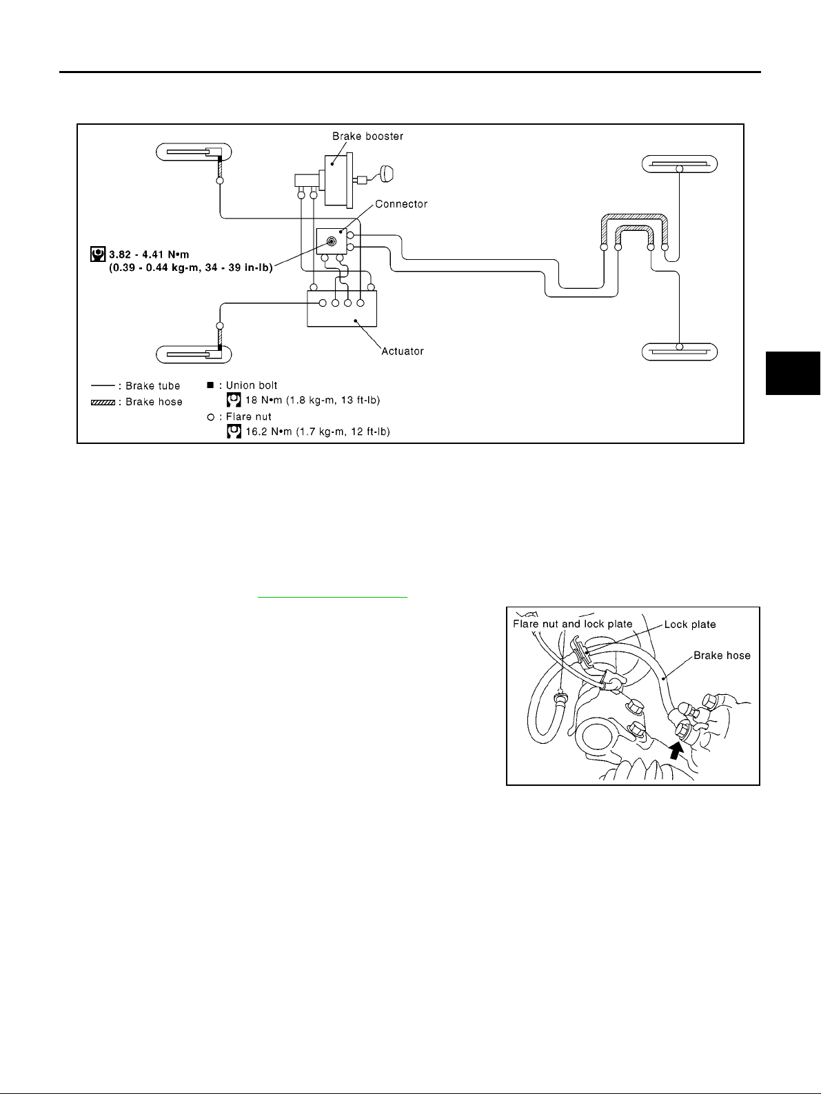
Hydraulic Circuit
EFS002GC
A
B
C
D
E
BR
MFIB9017E
Removal and Installation of Front Brake Piping and Brake Hose
EFS002GD
REMOVAL
CAUTION:
● Be careful not to splash brake fluid on painted areas; it may cause paint damage. If brake fluid is
splashed on painted areas, wash it away with water immediately.
● All hose must be free from excessive bending, twisting and pulling.
● Cover brake fluid line connections to prevent dust and other foreign material from entering.
1. Drain brake fluid. Refer to BR-9, "
2. Using a flare nut wrench, remove the flare nutso f the brake tube
and disconnect the brake tube from the brake hose.
3. Remove brake caliper union bolts and disconnect caliper
assembly from brake hose.
4. First remove the lock plate from the mounting positions of brake
tubes and struts, and then brake hose.
Drain and Refill" .
SFIA1118E
G
H
I
J
K
L
M
BR-11
Loading...