


 Loading...
MANUAL TRANSMISSION
SECTION MT
GI
MA
EM
LC
EC
CONTENTS
FE
FS5W71C |
|
PREPARATION ............................................................... |
3 |
Special Service Tools .................................................. |
3 |
Commercial Service Tools ........................................... |
5 |
NOISE, VIBRATION AND HARSHNESS (NVH) |
|
TROUBLESHOOTING ..................................................... |
6 |
NVH Troubleshooting Chart......................................... |
6 |
MANUAL TRANSMISSION.......................................... |
6 |
DESCRIPTION ................................................................. |
7 |
Cross-sectional View ................................................... |
7 |
ON-VEHICLE SERVICE .................................................. |
8 |
Replacing Rear Oil Seal .............................................. |
8 |
REMOVAL................................................................. |
8 |
INSTALLATION.......................................................... |
8 |
Position Switch Check ................................................. |
8 |
REMOVAL AND INSTALLATION ................................... |
9 |
Removal....................................................................... |
9 |
Installation.................................................................. |
10 |
OVERHAUL ................................................................... |
11 |
Case Components ..................................................... |
11 |
Gear Components ..................................................... |
12 |
Shift Control Components ......................................... |
13 |
DISASSEMBLY.............................................................. |
14 |
Case Components ..................................................... |
14 |
DISASSEMBLY........................................................ |
14 |
Shift Control Components ......................................... |
14 |
DISASSEMBLY........................................................ |
14 |
Gear Components ..................................................... |
15 |
DISASSEMBLY........................................................ |
15 |
INSPECTION.................................................................. |
18 |
Shift Control Components ......................................... |
18 |
INSPECTION........................................................... |
18 |
Gear Components ..................................................... |
18 |
INSPECTION........................................................... |
18 |
ASSEMBLY.................................................................... |
20 |
Gear Components ..................................................... |
20 |
ASSEMBLY ............................................................. |
20 |
Shift Control Components ......................................... |
26 |
ASSEMBLY ............................................................. |
26 |
Case Components ..................................................... |
27 |
ASSEMBLY ............................................................. |
27 |
SERVICE DATA AND SPECIFICATIONS (SDS) ......... |
30 |
General Specifications............................................... |
30 |
Gear End Play ........................................................... |
30 |
Clearance Between Baulk Ring and Gear ................ |
31 |
2ND & 3RD BAULK RING ........................................ |
31 |
Available Snap Rings ................................................ |
31 |
MAIN DRIVE GEAR BEARING.................................. |
31 |
MAINSHAFT FRONT................................................ |
31 |
COUNTER DRIVE GEAR ......................................... |
31 |
OD MAINSHAFT BEARING ...................................... |
32 |
Available Shims ......................................................... |
32 |
COUNTERSHAFT FRONT BEARING ........................ |
32 |
FS5R30A |
|
PREPARATION ............................................................. |
33 |
Special Service Tools ................................................ |
33 |
Commercial Service Tool........................................... |
35 |
NOISE, VIBRATION AND HARSHNESS (NVH) |
|
TROUBLESHOOTING ................................................... |
36 |
NVH Troubleshooting Chart....................................... |
36 |
MANUAL TRANSMISSION........................................ |
36 |
DESCRIPTION ............................................................... |
37 |
Cross-sectional View - 2WD Model........................... |
37 |
Cross-sectional View - 4WD Model........................... |
38 |
ON-VEHICLE SERVICE ................................................ |
39 |
Replacing Rear Oil Seal - 2WD Model ..................... |
39 |
REMOVAL............................................................... |
39 |
INSTALLATION........................................................ |
39 |
Position Switch Check ............................................... |
40 |
REMOVAL AND INSTALLATION ................................. |
41 |
Removal..................................................................... |
41 |
2WD MODEL........................................................... |
41 |
4WD MODEL........................................................... |
42 |
Installation.................................................................. |
43 |
OVERHAUL ................................................................... |
44 |
Case Components ..................................................... |
44 |
Gear Components ..................................................... |
45 |
CL
AT
TF
PD
AX
SU
BR
ST
RS
BT
HA
SC
EL
IDX
CONTENTS (Cont’d)
Shift Control Components (2/4WD models) .............. |
47 |
DISASSEMBLY.............................................................. |
48 |
Case Components ..................................................... |
48 |
DISASSEMBLY........................................................ |
48 |
Shift Control Components ......................................... |
49 |
DISASSEMBLY........................................................ |
49 |
Gear Components ..................................................... |
50 |
DISASSEMBLY........................................................ |
50 |
INSPECTION.................................................................. |
54 |
Shift Control Components ......................................... |
54 |
INSPECTION........................................................... |
54 |
Gear Components ..................................................... |
54 |
INSPECTION........................................................... |
54 |
ASSEMBLY.................................................................... |
56 |
Gear Components ..................................................... |
56 |
ASSEMBLY ............................................................. |
56 |
Shift Control Components ......................................... |
64 |
ASSEMBLY ............................................................. |
64 |
Case Components ..................................................... |
65 |
ASSEMBLY ............................................................. |
65 |
SERVICE DATA AND SPECIFICATIONS (SDS) ......... |
67 |
General Specifications............................................... |
67 |
Gear End Play ........................................................... |
67 |
Clearance Between Single Baulk Ring and Gear ..... |
67 |
DOUBLE BAULK RING ............................................ |
68 |
Distance Between Rear Surface of Reverse |
|
Cone and Reverse Baulk Ring.................................. |
68 |
Available Snap Ring .................................................. |
68 |
MAIN DRIVE GEAR SNAP RING .............................. |
68 |
MAINSHAFT FRONT SNAP RING............................. |
68 |
COUNTER GEAR REAR SNAP RING ....................... |
69 |
Available C-ring ......................................................... |
69 |
MAINSHAFT C-RING ............................................... |
69 |
Available Shim and Washer ...................................... |
69 |
TABLE FOR SELECTING PROPER COUNTER |
|
GEAR FRONT BEARING THRUST WASHER ............ |
69 |
REVERSE IDLER REAR THRUST WASHER ............. |
70 |
MT-2
PREPARATION |
|
FS5W71C |
|
Special Service Tools |
|
|
|
|
Special Service Tools |
|
NEMT0050 |
|
|
|
The actual shapes of Kent-Moore tools may differ from those of special service tools illustrated here.
Tool number (Kent-Moore |
Description |
||
No.) Tool name |
|
|
|
|
|
|
|
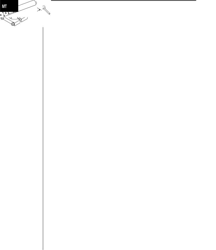
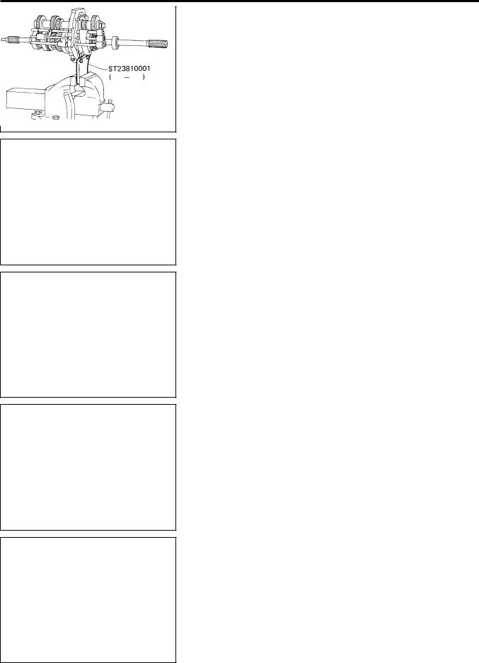
ST23810001 |
|
Fixing adapter plate with gear assembly |
|
( |
— |
) |
a: 166 mm (6.54 in) |
Adapter setting plate |
b: 270 mm (10.63 in) |
||
|
|
|
NT407 |
KV32101330 |
|
Removing overdrive mainshaft bearing |
|
(See J34286) |
|
a: 447 mm (17.60 in) |
|
Puller |
|
|
b: 100 mm (3.94 in) |
|
|
|
NT408 |
KV31100401 |
|
Pressing counter gear and mainshaft |
|
( |
— |
) |
|
Transmission press stand |
|
||
|
|
|
NT068 |
|
|
|
|
ST22520000 |
|
Tightening mainshaft lock nut |
|
(J26348) |
|
a: 100 mm (3.94 in) |
|
Wrench |
|
b: 41 mm (1.61 in) |
|
|
|
|
NT409 |
|
|
|
|
ST23540000 |
|
Removing and installing fork rod retaining pin |
|
(J25689-A) |
|
a: 2.3 mm (0.091 in) dia. |
|
Pin punch |
|
b: 4 mm (0.16 in) dia. |
|
|
|
|
NT442 |
|
|
|
|
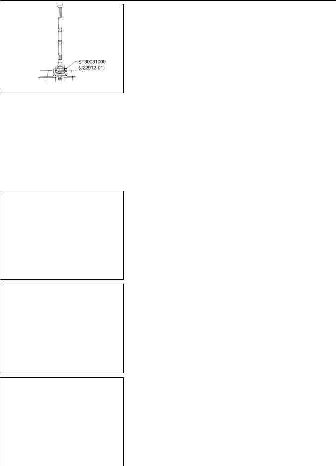
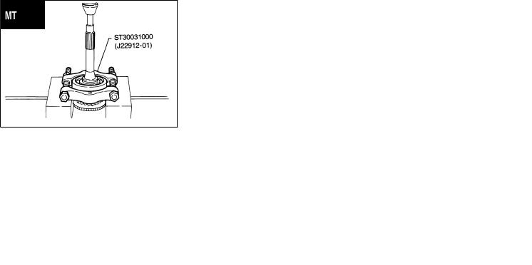
ST30031000 |
|
Removing and installing 1st gear bushing |
|
(J22912-01) |
|
Removing main drive gear bearing |
|
Puller |
|
|
a: 90 mm (3.54 in) dia. |
|
|
|
b: 50 mm (1.97 in) dia. |
|
|
|
NT411 |
|
|
|
|
ST23860000 |
|
Installing counter drive gear |
|
( |
— |
) |
a: 38 mm (1.50 in) dia. |
Drift |
|
|
b: 33 mm (1.30 in) dia. |
|
|
|
NT065 |
|
|
|
|
ST22360002 |
|
Installing counter gear front and rear end bear- |
|
(J25679-01) |
|
ings |
|
Drift |
|
|
a: 29 mm (1.14 in) dia. |
|
|
|
b: 23 mm (0.91 in) dia. |
|
|
|
NT065 |
|
|
|
|
|
|
|
MT-3 |
GI
MA
EM
LC
EC
FE
CL
AT
TF
PD
AX
SU
BR
ST
RS
BT
HA
SC
EL
IDX
|
PREPARATION |
|
FS5W71C |
Special Service Tools (Cont’d) |
|
|
|
|
|
|
|
|
|
|
|
Tool number (Kent-Moore |
Description |
|
|
No.) Tool name |
|
|
|
|
|
|
|
ST22350000 |
|
Installing OD gear bushing |
|
(J25678-01) |
|
a: 34 mm (1.34 in) dia. |
|
Drift |
|
b: 28 mm (1.10 in) dia. |
|
|
NT065 |
|
|
|
|
|
|
ST23800000 |
|
Installing front cover oil seal |
|
(J25691-01) |
|
a: 44 mm (1.73 in) dia. |
|
Drift |
|
b: 31 mm (1.22 in) dia. |
|
|
NT065 |
|
|
|
|
|
|
ST33400001 |
|
Installing rear oil seal |
|
(J26082) |
|
a: 60 mm (2.36 in) dia. |
|
Drift |
|
b: 47 mm (1.85 in) dia. |
|
|
NT086 |
|
|
|
|
|
|
ST33290001 |
|
Removing rear oil seal |
|
(J34286) |
|
a: 250 mm (9.84 in) |
|
Puller |
|
b: 160 mm (6.30 in) |
|
|
NT414 |
|
|
ST30720000 |
|
Installing mainshaft ball bearing |
|
(J25405) |
|
a: 77 mm (3.03 in) dia. |
|
Drift |
|
b: 55.5 mm (2.185 in) dia. |
|
|
NT115 |
|
|
|
|
|
|
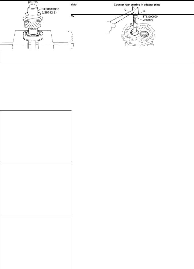
ST30613000 |
|
Installing main drive gear bearing |
|
(J25742-3) |
|
a: 71.5 mm (2.815 in) dia. |
|
Drift |
|
b: 47.5 mm (1.870 in) dia. |
|
|
NT073 |
|
|
|
|
|
|
ST33200000 |
|
Installing counter rear bearing |
|
(J26082) |
|
a: 60 mm (2.36 in) dia. |
|
Drift |
|
b: 44.5 mm (1.752 in) dia. |
|
|
NT091 |
|
|
|
|
|
|
(J-26349–A) |
|
Removing and installing mainshaft bearing |
|
Bearing Remover and |
|
(Use with J-25726–B) |
|
Installer Set |
|
|
|
|
WMT065 |
|
|
|
|
|
|
MT-4
|
PREPARATION |
|
FS5W71C |
|
|
|
|
|
Special Service Tools (Cont’d) |
||||
|
|
|
|
|
|
|
|
|
|
|
|
|
|
Tool number (Kent-Moore |
Description |
|
|
|
|
|
No.) Tool name |
|
|
|
|
|
GI |
|
|
|
|
|
|
|
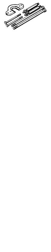
(J-34286) |
|
|
|
|
||
|
Removing races |
|||||
Rear Race Puller |
|
|
|
|
|
MA |
|
|
|
|
|
|
|
|
|
|
|
|
|
EM |
|
WMT066 |
|
|
|
|
LC |
|
|
|
|
|
|
|
|
|
|
|
|
||
(J-39856) |
|
Removing gears and bearings |
||||
Gear and Bearing |
|
|
|
|
|
EC |
Removal Kit |
|
|
|
|
|
|
|
|
|
|
|
|
FE |
|
WMT067 |
|
|
|
|
CL |
|
|
|
|
|
|
|
|
|
|
|
|
|
|
|
Commercial Service Tools |
|||||
|
|
|
NEMT0051 |
|||
Tool name |
Description |
|
|
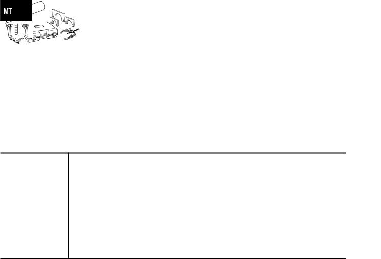
Puller |
Removing counter bearings, counter drive and OD |
|
gears |
|
NT077 |
Drift |
Installing countershaft rear end bearing |
|
a: 40 mm (1.57 in) dia. |
|
b: 30 mm (1.18 in) dia. |
|
NT074 |
MT-5
AT
TF
PD
AX
SU
BR
ST
RS
BT
HA
SC
EL
IDX

NOISE, VIBRATION AND HARSHNESS (NVH) |
NEMT0052 |
TROUBLESHOOTING |
|
FS5W71C |
NVH Troubleshooting Chart
NVH Troubleshooting Chart
NEMT0052S01
Use the chart below to help you find the cause of the symptom. The numbers indicate the order of the inspection. If necessary, repair or replace these parts.
MANUAL TRANSMISSION
|
|
|
|
|
|
|
|
|
|
|
|
NEMT0052S0101 |
|
Reference page |
|
MAtoRefer-38, “CheckingM/T Oil”. |
|
MT-11 |
MT-11 |
MT-13 |
MT-13 |
MT-12 |
MT-12 |
MT-12 |
|
MT-12 |
|
|
|
|
|
|
|
|
|
|
|
|
|
||
|
|
|
|
|
|
|
|
|
|
|
|
|
|
SUSPECTED PARTS |
|
|
|
|
|
CHECK BALL (Worn or damaged) |
|
|
|
|
|
|
|
|
|
|
|
|
AND |
|
|
|
|
|
|
||
(Possible cause) |
|
|
|
|
|
|
|
|
|
|
|
||
|
|
OIL (Oil level is low.) |
OIL (Wrong oil.) |
OIL (Oil level is high.) |
GASKET (Damaged) |
OIL SEAL (Worn or damaged) |
CHECK PLUG RETURN SPRING |
SHIFT FORK (Worn) |
GEAR (Worn or damaged) |
BEARING (Worn or damaged) |
BAULK RING (Worn or damaged) |
|
INSERT SPRING (Damaged) |
|
|
|
|
|
|
|
|
|
|
|
|
|
|
|
Noise |
1 |
2 |
|
|
|
|
|
3 |
3 |
|
|
|
|
|
|
|
|
|
|
|
|
|
|
|
|
|
Symptom |
Oil leakage |
|
3 |
1 |
2 |
2 |
|
|
|
|
|
|
|
|
|
|
|
|
|
|
|
|
|
|
|
|
|
Hard to shift or will not shift |
|
1 |
1 |
|
|
|
|
|
|
2 |
|
2 |
|
|
|
|
|
|
|
|
|
|
|||||
|
|
|
|
|
|
|
|
|
|
|
|
|
|
|
Jumps out of gear |
|
|
|
|
|
1 |
2 |
2 |
|
|
|
|
|
|
|
|
|
|
|
|
|
|
|
|
|
|
MT-6
DESCRIPTION |
|
NEMT0053 |
|
FS5W71C |
|
|
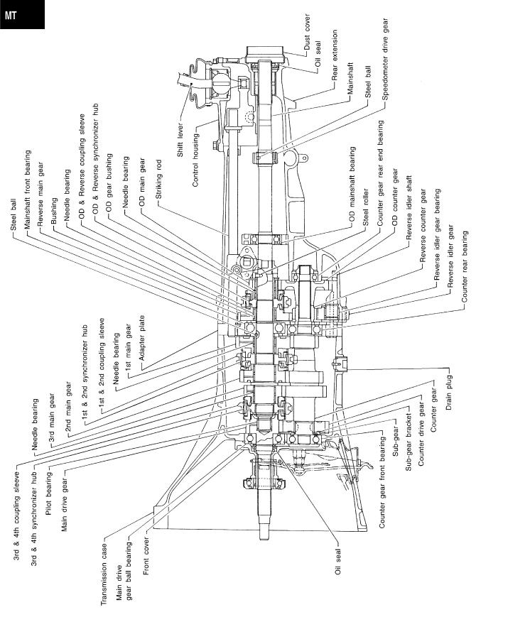
Cross-sectional View |
|
|
|
|
Cross-sectional View |
|
NEMT0053S01 |
|
|
|
SMT153D
GI
MA
EM
LC
EC
FE
CL
AT
TF
PD
AX
SU
BR
ST
RS
BT
HA
SC
EL
IDX
MT-7
ON-VEHICLE SERVICE |
FS5W71C |
Replacing Rear Oil Seal
Replacing Rear Oil Seal
NEMT0054
REMOVAL
NEMT0054S01
1.Remove the propeller shaft. Refer to PD-9, “Removal and Installation”.
2.Remove rear oil seal using Tool.
Always replace with a new seal once it has been removed.
AMT079
INSTALLATION
NEMT0054S02
1.Install new oil seal until it stops.
Apply multi-purpose grease to seal lip of oil seal before installing.
2.Install any part removed.
SMT480CA
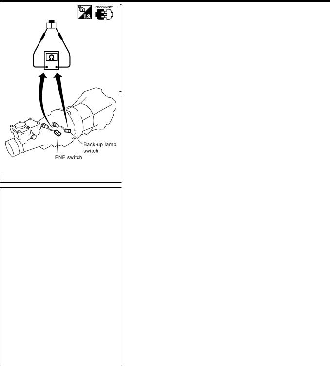
Position Switch Check
Check continuity. |
|
NEMT0055 |
|
|
|
||
|
|
|
|
|
Switch |
Gear position |
Continuity |
|
|
|
|
|
Back-up lamp switch |
Reverse |
Yes |
|
|
|
|
|
Except reverse |
No |
|
|
|
||
|
|
|
|
|
Park/neutral position |
Neutral |
Yes |
|
|
|
|
|
(PNP) switch |
Except neutral |
No |
|
|
||
|
|
|
|
SMT981D
MT-8
REMOVAL AND INSTALLATION |
NEMT0056 |
FS5W71C |
|
|
Removal |
|
|
Removal |
NEMT0056S01 |
|
WMT030
CAUTION:
Before separating the transmission from the engine, remove the crankshaft position sensor (OBD) from the transmission. Be careful not to damage sensor edge or ring gear teeth.
GI
MA
EM
LC
EC
FE
CL
AT
TF
PD
AX
SU
BR
ST
RS
BT
HA
SC
EL
IDX
MT-9
REMOVAL AND INSTALLATION |
FS5W71C |
Removal (Cont’d)
NOTE:
To prevent oil spills, drain transmission oil before removing transmission or insert plug into rear oil seal after removing propeller shaft.
Be careful not to damage spline, sleeve yoke, and rear oil seal when removing propeller shaft.
1.Remove battery negative terminal.
2.Remove the crankshaft position sensor (OBD) from transmission upper side.
3.Remove the clutch operating cylinder from transmission.
4.Disconnect the vehicle speed sensor, back-up switch, and park/neutral position (PNP) switch harness connectors.
5.Remove the starter motor from transmission.
6.Disconnect the exhaust hanger.
7.Remove the propeller shaft. Refer to PD-9, “Removal and Installation”.
8.Remove the shift lever.
9.Support the engine by placing a jack under the oil pan.
Do not place jack under oil pan drain plug.
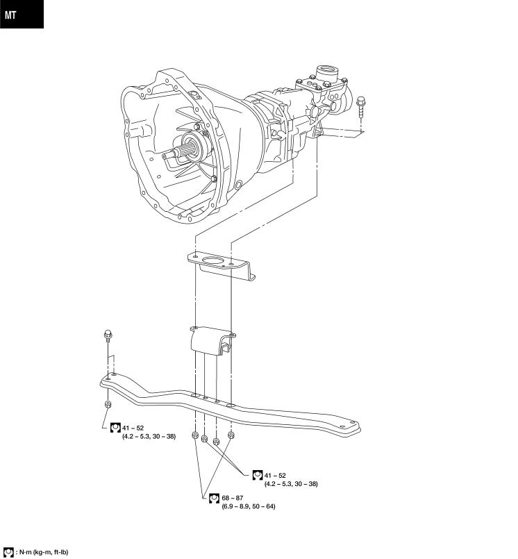
10.Remove the transmission crossmember.
11.Separate the transmission from the engine.
WARNING:
Support manual transmission while removing it.
SMT099A
Installation |
|
NEMT0056S02 |
|||
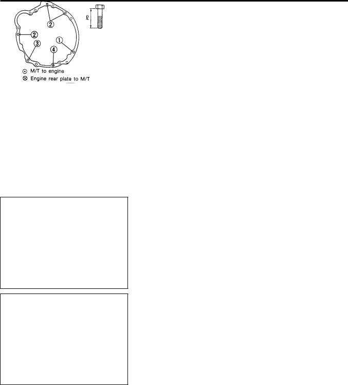
1. Tighten bolts securing transmission. |
|||||
|
|||||
|
|
|
|
|
|
|
Bolt No. |
|
Tightening torque N·m (kg-m, ft-lb) |
mm (in) |
|
|
|
|
|
|
|
1 |
|
40 - 49 (4.0 - 5.0, 29 - 36) |
65 (2.56) |
||
|
|
|
|
|
|
2 |
|
40 - 49 (4.0 - 5.0, 29 - 36) |
58 (2.28) |
||
|
|
|
|
|
|
3* |
|
16 - 21 (1.6 - 2.2, 12 - 15) |
25 (0.98) |
||
|
|
|
|
|
|
4 |
|
16 - 21 (1.6 - 2.2, 12 - 15) |
16 (0.63) |
||
|
|
|
|
|
|
AMT190 |
*: With nut |
2.Installation is in the reverse order of removal.
MT-10
OVERHAUL |
|
NEMT0057 |
|
FS5W71C |
|
|
Case Components |
|
|
|
|
Case Components |
|
NEMT0057S01 |
|
|
|
WMT062
GI
MA
EM
LC
EC
FE
CL
AT
TF
PD
AX
SU
BR
ST
RS
BT
HA
SC
EL
IDX
MT-11

OVERHAUL |
FS5W71C |
Gear Components
Gear Components
NEMT0057S02
WMT063
MT-12
OVERHAUL |
|
FS5W71C |
|
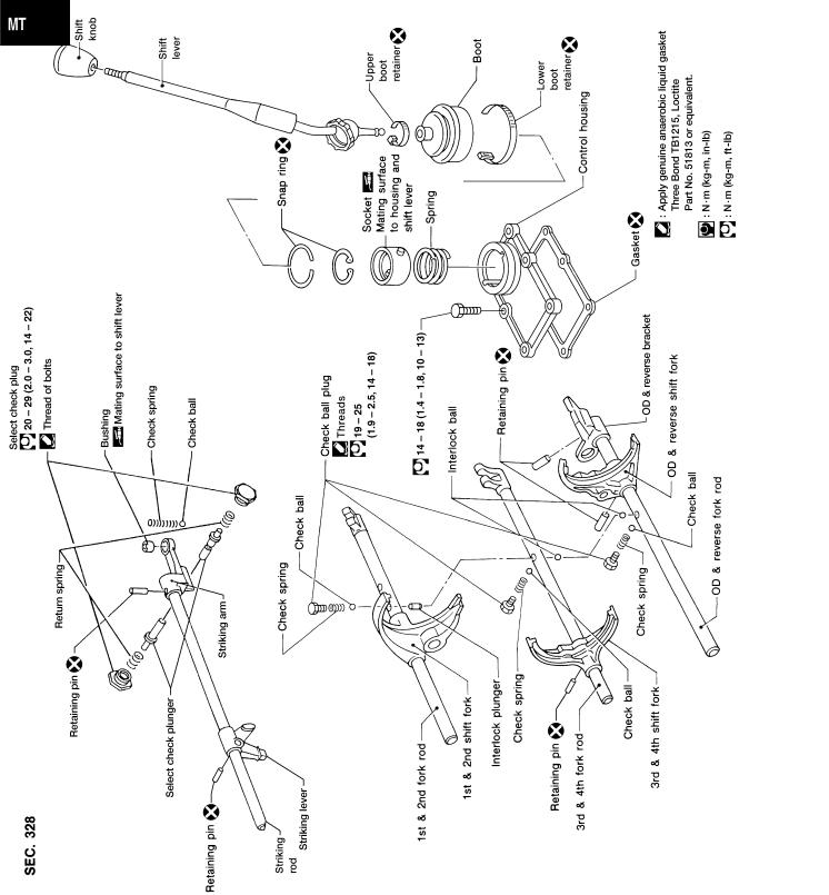
Shift Control Components |
|
|
|
|
Shift Control Components |
|
NEMT0057S03 |
|
|
|
CAUTION:
To avoid damage when replacing shift knob, remove shift lever GI with knob, as assembled.
MA
EM
LC
EC
FE
CL
AT
TF
PD
AX
SU
BR
ST
RS
BT
HA
SC
WMT040
EL
IDX
MT-13
DISASSEMBLY |
FS5W71C |
Case Components
Case Components
DISASSEMBLY
NEMT0058
1.Remove rear extension.
a.Remove control housing, check ball, return spring plugs, select check plungers and return springs. Also remove reverse check plug, check spring and check ball.
Be careful not to lose check balls.
SMT161D
b.Drive out striking lever retaining pin.
c.Remove striking lever from striking rod.
d.Remove rear extension by lightly tapping on it.
AMT132
2.Remove front cover, gasket, counter gear front bearing shim and main drive gear ball bearing snap ring.
3.Separate transmission case from adapter plate by lightly tapping on it.
AMT131
4.Remove oil seal from front cover.
Be careful not to damage mating surface of front cover.
SMT166D
Shift Control Components
DISASSEMBLY
NEMT0059
1.Set up Tool on adapter plate.
2.Remove striking rod from adapter plate.
3.Remove check ball plugs, check springs, and check balls.
SMT545A
MT-14
DISASSEMBLY |
|
FS5W71C |
|
Shift Control Components (Cont’d) |
|
|
|
|
4.Drive out retaining pins. Then drive out fork rods and remove interlock balls.
SMT984
Gear Components
DISASSEMBLY
NEMT0060
1.Before disassembly, measure the end play of each gear.
If end play is not within the specified limit, disassemble and
inspect the parts.
Replace any part which is worn or damaged. Refer to “Gear
End Play”, MT-30.
SMT025
2.Mesh 2nd and reverse gear, then remove counter gear front
bearing using a suitable puller.
3.Remove snap ring, then remove sub-gear bracket, sub-gear spring and sub-gear.
SMT174A
GI
MA
EM
LC
EC
FE
CL
AT
TF
PD
AX
4.Remove counter drive gear together with main drive gear
assembly using a suitable puller.
When removing main drive gear assembly, be careful not
to drop pilot bearing or baulk ring.
5.Remove snap ring, then remove 3rd and 4th synchronizer assembly and 3rd main gear.
SMT162A
SU
BR
ST
RS
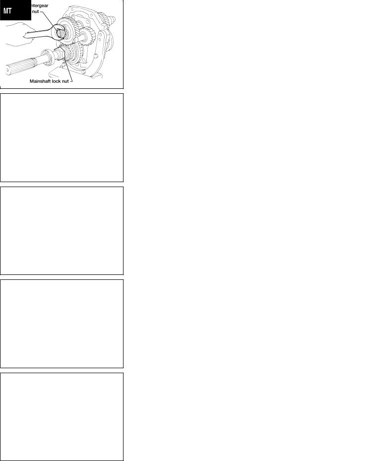
6. Disassemble parts at rear of adapter plate as follows:
a.Release staking on both countergear and mainshaft lock nuts, then loosen both nuts.
Mainshaft lock nut: Left-hand thread
AMT133
BT
HA
SC
EL
IDX
MT-15
DISASSEMBLY |
FS5W71C |
Gear Components (Cont’d)
b.Remove overdrive counter gear together with counter gear rear end bearing using a suitable puller.
c.Remove reverse counter gear and spacer.
d.Remove snap rings from reverse idler shaft, then remove reverse idler gear, thrust washers and reverse idler gear bearing.
e.Remove snap ring and pull out overdrive mainshaft bearing, then remove snap ring. (2WD model)
f.Remove mainshaft lock nut.
g.Remove speedometer drive gear and steel ball. (2WD model)
SMT547A h. Remove thrust washer, steel roller, roller bearing and washer.
i.Remove overdrive main gear, needle bearing and baulk ring (overdrive).
j.Remove counter gear by tapping on rear end of counter gear.
k.Press out overdrive gear bushing and overdrive & reverse synchronizer assembly.
l.Remove reverse main gear and needle bearing.
m.Press out reverse gear bushing.
SMT554A
7.Remove thrust washer, steel ball, 1st main gear and needle bearing.
Be careful not to lose steel ball.
SMT383A
8.Press out 1st gear bushing together with 2nd main gear using Tool.
Remove 2nd gear needle bearing.
TM049A
MT-16
DISASSEMBLY |
|
FS5W71C |
|
Gear Components (Cont’d) |
|
|
|
|
9.Remove main drive gear ball bearing.
a.Remove snap ring.
b.Remove main drive gear ball bearing.
SMT420A
MT-17
GI
MA
EM
LC
EC
FE
CL
AT
TF
PD
AX
SU
BR
ST
RS
BT
HA
SC
EL
IDX
INSPECTION |
FS5W71C |
Shift Control Components
Shift Control Components
INSPECTION
NEMT0061
Check contact and sliding surfaces of fork rods for wear, scratches, projections and other damage.
SMT075C
SMT386A
SMT550A
Gear Components
INSPECTION
NEMT0062
Gears and Shafts
NEMT0062S01
Check shafts for cracks, wear and bending.
Check gears for excessive wear, chips and cracks.
Synchronizers
NEMT0062S02
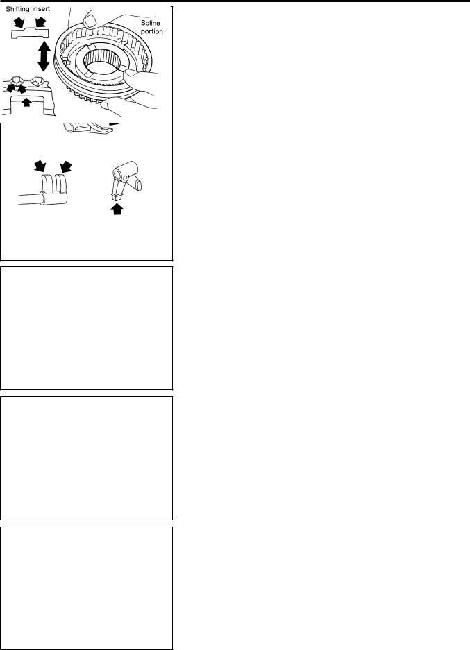
Check spline portion of coupling sleeves, synchronizer hubs, and gears for wear, chips, and cracks.
Check baulk rings for cracks and deformation.Check shifting inserts for wear and deformation.Check insert spread springs for deformation.
SMT427C
MT-18
INSPECTION |
|
FS5W71C |
|
Gear Components (Cont’d) |
|
Measure baulk ring wear.
1)Measure clearance between baulk ring and gear. Refer to
“Clearance Between Baulk Ring and Gear”, MT-31. |
GI |
If the clearance is less than the wear limit, replace baulk ring.
MA
EM
SMT140 |
LC |
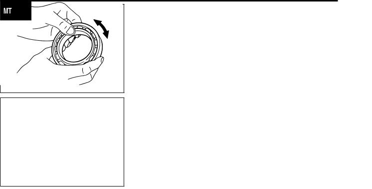
Bearings
NEMT0062S03
Make sure all bearings roll freely and are free from noise, EC cracks, pitting or wear.
FE
CL
SMT418A
AT
TF
PD
AX
SU
BR
ST
RS
BT
HA
SC
EL
IDX
MT-19
ASSEMBLY |
FS5W71C |
Gear Components
Gear Components
ASSEMBLY
NEMT0063
AMT185
1.Install bearings into case components.
2.Assemble adapter plate parts.
Install oil gutter on adapter plate and expand on rear side.
Install bearing retainer.
a.Insert reverse idler shaft, then install bearing retainer.
SMT778C
b.Tighten each screw, then stake each one at two points.
SMT674C
3.Install main drive gear ball bearing.
a.Press main drive gear ball bearing.
SMT425A
MT-20
ASSEMBLY |
|
FS5W71C |
|
Gear Components (Cont’d) |
|
|
|
|
b.Select and install proper main drive gear snap ring to achieve proper clearance of groove. Refer to “MAIN DRIVE GEAR
BEARING”, MT-31.
Allowable clearance of groove: 0 - 0.13 mm (0 - 0.0051 in)
SMT170D
4.Assemble synchronizers.
Assemble the 1st and 2nd synchronizer.
SMT054C
Check coupling sleeve and synchronizer hub orientation.
SMT206C
GI
MA
EM
LC
EC
FE
CL
AT
TF
PD
AX
SU
BR
ST
RS
BT
HA
SC
EL
IDX
MT-21
Loading...