


SCRUBTEC  8
8
SCRUBTEC 866
SCRUBTEC 871
SCRUBTEC 871C
SCRUBTEC 886
Operator’s Manual
and Parts List
Models: 05370F, 05370G, 05390F, 05400F, 05400G, 05410F, 05420F, 56380673
EN English (2-27) |
READ THIS MANUAL |
Parts List (29-64)
Form No. 71492A 10/08, Rev. 9/10

ENGLISH EN
READ THIS BOOK
CAUTION: Read the Operator’s Manual before using the appliance.
This book has important information for the use and safe operation of this machine. Failure to read this book prior to operating or attempting any service or maintenance procedure to your Nilfisk ALTO machine could result in injury to you or to other personnel; damage to the machine or to other property could occur as well. You must have training in the operation of this machine before using it. If operator(s) cannot read this manual, have it explained fully before attempting to operate this machine.
All directions given in this book are as seen from the operator’s position at the rear of the machine.
|
Table of Contents |
|
Table of Contents |
Operator Safety Instructions.................................................................................................................................................................... |
3 |
Introduction ............................................................................................................................................................................................. |
4 |
Machine Specifications............................................................................................................................................................................ |
5 |
Procedures For Transporting................................................................................................................................................................... |
6 |
Symbols Used On SCRUBTEC............................................................................................................................................................... |
7 |
Machine Control Panel ............................................................................................................................................................................ |
8 |
Machine Controls and Features .............................................................................................................................................................. |
10 |
How To Prepare The Machine For Operation.......................................................................................................................................... |
10 |
How To Operate The Machine................................................................................................................................................................. |
17 |
Maintenance............................................................................................................................................................................................ |
21 |
How To Correct Problems In The Machine.............................................................................................................................................. |
25 |
Section II Parts and Service Manual |
|
Solution Tank Assembly........................................................................................................................................................................... |
30-31 |
Recovery Tank Assembly ........................................................................................................................................................................ |
32-33 |
Handle Assembly (Disc and BOOST Models) ......................................................................................................................................... |
34-35 |
Handle Assembly (Cylindrical Model) ...................................................................................................................................................... |
36-37 |
Electrical Box Assembly .......................................................................................................................................................................... |
38-39 |
Squeegee Holder Assembly .................................................................................................................................................................... |
40-41 |
Squeegee Assembly (32.5”) .................................................................................................................................................................... |
42-43 |
Squeegee Assembly (35”) ....................................................................................................................................................................... |
44-45 |
Squeegee Assembly (41”) ....................................................................................................................................................................... |
46-47 |
Frame Assembly...................................................................................................................................................................................... |
48-49 |
Brush Head Assembly (866).................................................................................................................................................................... |
50-51 |
Brush Head Assembly (871).................................................................................................................................................................... |
52-53 |
Brush Head Assembly (886).................................................................................................................................................................... |
54-55 |
Brush Head Assembly (BOOST 8) .......................................................................................................................................................... |
56-57 |
Brush Head Assembly (871C) ................................................................................................................................................................. |
58-59 |
Chemical Mixing Kit................................................................................................................................................................................. |
60-61 |
Electrical Schematic ................................................................................................................................................................................ |
62-63 |
Connection Diagram................................................................................................................................................................................ |
64 |
Accessories ............................................................................................................................................................................................. |
65 |
-2- FORM NO. 71492A |
revised 9/10 |
Nilfisk ALTO Operator’s Manual (EN) - SCRUBTEC 866, 871, 866, Boost 8 and 871C |

ENGLISH EN
OPERATOR SAFETY INSTRUCTIONS
|
DANGER: |
Failure to read and observe all DANGER statements could result in severe bodily injury |
|
|
|
||
|
|
or death. Read and observe all DANGER statements found in your Owner’s Manual and |
|
|
|
on your machine. |
|
|
WARNING: |
Failure to read and observe all WARNING statements could result in injury to you or to |
|
|
|
other personnel; property damage could occur as well. Read and observe all WARNING |
|
|
|
statements found in your Owner’s Manual and on your machine. |
|
|
CAUTION: |
Failure to read and observe all CAUTION statements could result in damage to the |
|
|
|
machine or to other property. Read and observe all CAUTION statements found in your |
|
|
|
Owner’s Manual and on your machine. |
|
|
|
|
|
|
|
|
|
DANGER: Failure to read the Owner’s Manual prior to operating or attempting any service or maintenance procedure to your Nilfisk ALTO machine could result in injury to you or to other personnel; damage to the machine or to other property could occur as well. You must have training in the operation of this machine before using it. If your operator(s) cannot read English, have this manual explained fully before attempting to operate this
machine.
DANGER: Operating a machine that is not completely or fully assembled could result in injury or property damage. Do not operate this machine until it is completely assembled. Inspect the machine carefully before operation.
DANGER: Machines can cause an explosion when operated near flammable materials and vapors. Do not use this machine with or near fuels, grain dust, solvents, thinners, or other flammable materials. This machine is not suitable for picking up hazardous dust.
DANGER: Lead acid batteries generate gases which can cause an explosion. Keep sparks and flames away from batteries. Do not smoke around the machine. Charge the batteries only in an area with good ventilation. Make sure that you unplug the AC charger from the wall outlet before operating the machine.
DANGER: Working with batteries can be dangerous! Always wear eye protection and protective clothing when working near batteries. Remove all jewelry. Do not put tools or other metal objects across the battery terminals, or the
tops of the batteries.
DANGER: Using a charger with a damaged power cord could result in an electrocution. Do not use the charger if the power cord is damaged.
WARNING: Operating this machine from anywhere other than the back of the machine could result in injury or damage. Operate this machine only from the rear.
WARNING: This machine is heavy. Get assistance before attempting to transport or move it. Use two able persons to move the machine on a ramp or incline. Always move slowly. Do not turn the machine on a ramp. If operating machine on a gradient over 2%, do not stop, turn or park. Read the “Procedures For Transporting” in this manual before transporting.
WARNING: Machines can topple over if guided over the edges of stairs or loading docks and cause injury or damage. Stop and leave this machine only on a level surface. When you stop the machine, turn the key “OFF”.
WARNING: Maintenance and repairs performed by unauthorized personnel could result in damage or injury. Maintenance and repairs must be performed by authorized Nilfisk ALTO personnel only.
WARNING: Any alterations or modifications of this machine could result in damage to the machine or injury to the operator or other bystanders. Alterations or modifications not authorized by the manufacturer voids any and all warranties and liabilities.
Nilfisk ALTO Operator’s Manual (EN) - SCRUBTEC 866, 871, 866, Boost 8 and 871C |
FORM NO. 71492A - 3 - |

ENGLISH EN
WARNING: Electrical components of this machine can “short-out” if exposed to water or moisture. Keep the electrical components of the machine dry. Wipe the machine down after each use. For storage, keep the machine in a dry building.
WARNING: To reduce the risk of fire, when replacing fuse, replace only with same type and rating of fuse that comes with machine.
WARNING: Operating a machine without observing all labels and instructional information could result in injury or damage. Read all machine labels before attempting to operate. Make sure all of the labels and instructional information are attached or fastened to the machine. Get replacement labels and plates from your Nilfisk ALTO distributor.
WARNING: Wet floor surfaces can be slippery. Water solutions or cleaning materials used with this type of machine can leave wet areas on the floor surface. These areas can cause a dangerous condition for the operator or other persons. Always put “Caution” signs around/near the area you are cleaning.
WARNING: Improper discharge of waste water may damage the environment and be illegal. The United States Environmental Protection Agency has established certain regulations regarding discharge of waste water. Also, city and state regulations regarding this discharge may be in your area. Understand and follow the regulations in your area. Be aware of the environmental hazards of chemicals that you dispose.
CAUTION: Use of this machine to move other objects or to climb on could result in injury or damage. Do not use this machine as a step or furniture. Do not ride on this machine.
CAUTION: Your machine warranty will be voided if anything other than genuine Nilfisk ALTO parts are used on your machine. Always use Nilfisk ALTO parts for replacement.
Introduction :
Scrubtec 866, 871, 886, BOOST 8 and 871C automatic scrubbers are efficient and superior floor cleaning machines. The Scrubtec 886 uses two brushes or pads to scrub a path 86 cm wide. The Scrubtec 871 uses two brushes or pads to scrub a path 71 cm wide. The Scrubtec 866 uses two brushes or pads to scrub a path 66 cm wide. The Scrubtec BOOST 8 uses one pad or brush to scrub a path 71 cm wide. The Scrubtec 871C uses two brushes to scrub a path 71 cm wide. A squeegee wipes the floor while the vacuum motor removes the dirty solution from the floor in one pass.
Scrubtec 866, 871, 886, BOOST 8 and 871C automatic scrubbers come complete with three battery connector cables, one battery cable, one battery charger and one operator’s manual.
-4- FORM NO. 71492A |
Nilfisk ALTO Operator’s Manual (EN) - SCRUBTEC 866, 871, 866, Boost 8 and 871C |

|
|
|
|
|
|
|
ENGLISH |
EN |
|||
|
|
|
|
|
|
|
|
|
|
|
|
|
|
|
|
|
|
|
|
|
|
|
|
Machine Specifications |
|
|
|
|
|
|
|
|
|
||
|
|
|
|
|
|
|
|
|
|
|
|
|
|
Model |
Scrubtec 866 |
|
Scrubtec 871 |
Scrubtec 886 |
|
|
|
|
|
|
|
Pad / Brush Size |
(2) 13” (33 cm) |
|
(2) 14” (36 cm) |
(2) 17” (43 cm) |
|
|
|
|
|
|
|
Brush Motor (s) |
(2) 3/4 hp (.56 kw) |
|
(2) 3/4 hp (.56 kw) |
(2) 3/4 hp (.56 kw) |
|
|
|
|
|
|
|
|
200 RPM |
|
200 RPM |
200 RPM |
|
|
|
|
|
|
|
Cleaning Width |
26” (66 cm) |
|
28” (71 cm) |
34” (86.4 cm) |
|
|
|
|
|
|
|
Brush Pressure |
1st - 80 lbs. (36 kg) |
|
1st - 80 lbs. (36 kg) |
1st - 80 lbs. (36 kg) |
|
|
|
|
|
|
|
|
2nd - 150 lbs. (68 kg) |
|
2nd - 150 lbs. (68 kg) |
2nd - 150 lbs. (68 kg) |
|
|
|
|
|
|
|
Brush Retention |
Gimbal |
|
Gimbal |
Gimbal |
|
|
|
|
|
|
|
Brush Head |
Steel Deck w/ Bristle Skirt |
|
Steel Deck w/ Bristle Skirt |
Steel Deck w/Bristle Skirt |
|
|
|
|
|
|
|
Water Retention |
|
|
|
|
|
|
|
|
|
|
|
Squeegee Width |
32.5” (81 cm) |
|
35” (89 cm) |
41” (107 cm) |
|
|
|
|
|
|
|
Width of Machine |
28” (71 cm) Head |
|
30” (76 cm) Head |
35.7” (91 cm) Head |
|
|
|
|
|
|
|
|
23.5” (60 cm) Body |
|
23.5” (60 cm) Body |
23.5” (60 cm) Body |
|
|
|
|
|
|
|
Length of Machine |
61” (155 cm) |
|
62” (157 cm) |
64” (162 cm) |
|
|
|
|
|
|
|
Height of Machine |
|
|
|
44” (112 cm) |
|
|
|
|
|
|
|
Weight w/250 Ah batteries |
796 lbs. (361.1 kg) |
|
800 lbs. (362.9 kg) |
791 lbs. (358.8 kg) |
|
|
|
|
|
|
|
and full solution tank |
|
|
|
|
|
|
|
|
|
|
|
Power Supply |
|
|
24 volt, (4 - 6 volt batteries) |
|
|
|
|
|
|
|
|
Vacuum Motor |
|
.75 hp (550W), 3 stage, tangential discharge |
|
|
|
|
|
||
|
|
Vacuum Motor Protection |
|
|
Electronic Float Shut-Off |
|
|
|
|
|
|
|
|
Solution Tank |
|
|
23 gallons (87 liters) |
|
|
|
|
|
|
|
|
Solution Fill |
|
|
Rear Fill with Bucket or Hose |
|
|
|
|
|
|
|
|
Solution Flow |
|
|
0 - 1 gal/min (0 - 3.8 liters/min) |
|
|
|
|
|
|
|
|
Recovery Tank |
|
|
23 gallons (87 liters) |
|
|
|
|
|
|
|
|
Motor Traction |
|
|
|
.44 hp (.33 kw) |
|
|
|
|
|
|
|
Speed Forward |
|
|
0 - 260 ft/min (0 - 4.8 km/h) |
|
|
|
|
|
|
|
|
Speed Reverse |
|
|
0 - 174 ft/min (0 - 3.2 km/h) |
|
|
|
|
|
|
|
|
Drive Wheel |
|
(2) 10.24” (260 mm) x 3.35” (85 mm) Light Gray, Non-Marking, Foam Filled |
|
|
|
|
|||
|
|
Caster |
|
|
(2) 3.94” (10 cm) Polyurethane |
|
|
|
|
|
|
|
|
Squeegee Material |
|
Urethane Front Blade and Rear Blade |
|
|
|
|
|
||
|
|
Cleaning Grade |
|
|
2 % |
|
|
|
|
|
|
|
|
Charger |
|
|
On Board, 24 volt, 25 amp |
|
|
|
|
|
|
|
|
Vibration @ handle |
|
|
|
<2.5m/s2 |
|
|
|
|
|
|
|
Sound test @ operator’s ear |
65 dBA |
|
65 dBA |
67 dBA |
|
|
|
|
|
|
|
|
|
|
|
|
|
|
|
|
|
|
|
Model |
Scrubtec 871 C |
|
Scrubtec BOOST 8 |
|
|
|
|
|
|
|
|
Pad / Brush Size |
(2) 5.75” x 28” (14.6 x 69cm) |
|
14” x 28” (35.6 x 71cm) |
|
|
|
|
|
|
|
|
Brush Motor (s) |
(2) .81 hp (.6 kw) |
|
3/4 hp (.56 kw) |
|
|
|
|
|
|
|
|
|
613 RPM |
|
2250 RPM |
|
|
|
|
|
|
|
|
Cleaning Width |
28” (71 cm) |
|
28” (71 cm) |
|
|
|
|
|
|
|
|
Brush Pressure |
80 lbs. (36 kg) |
|
1st - 65 lbs. (29.5 kg) |
|
|
|
|
|
|
|
|
|
|
|
|
2nd - 125 lbs. (56.7 kg) |
|
|
|
|
|
|
|
Brush Retention |
N/A |
|
Hook & Loop |
|
|
|
|
|
|
|
|
Brush Head |
Side Skirts |
|
N/A |
|
|
|
|
|
|
|
|
Water Retention |
|
|
|
|
|
|
|
|
|
|
|
Squeegee Width |
35” (89 cm) |
|
35” (89 cm) |
|
|
|
|
|
|
|
|
Width of Machine |
30.69” (78 cm) Head |
|
28.75” (73 cm) Head |
|
|
|
|
|
|
|
|
|
23.5” (60 cm) Body |
|
23.5” (60 cm) Body |
|
|
|
|
|
|
|
|
Length of Machine |
59.5” (151 cm) |
|
60.5” (154 cm) |
|
|
|
|
|
|
|
|
Height of Machine |
|
|
|
44” (112 cm) |
|
|
|
|
|
|
|
Weight w/250 Ah batteries |
792 lbs. (359.3 kg) |
|
794 lbs. (360.2 kg) |
|
|
|
|
|
|
|
|
and full Solution Tank |
|
|
|
|
|
|
|
|
|
|
|
Power Supply |
|
24 volt, (4 - 6 volt batteries) |
|
|
|
|
|
||
|
|
Vacuum Motor |
|
.75 hp (550W), 3 stage, tangential discharge |
|
|
|
|
|
||
|
|
Vacuum Motor Protection |
|
|
Electronic Float Shut-Off |
|
|
|
|
|
|
|
|
Solution Tank |
|
|
23 gallons (87 liters) |
|
|
|
|
|
|
|
|
Solution Fill |
|
|
Rear Fill with Bucket or Hose |
|
|
|
|
|
|
|
|
Solution Flow |
0 - 1 gal/min (0 - 3.8 liters/min) |
|
Normal BOOST Scrubbing .12 gal/min (.45 liters/min), |
|
|
|
|
||
|
|
|
|
|
|
Full range .0 - .65 gal/min (0 -2.5 liters/min) |
|
|
|
|
|
|
|
Recovery Tank |
|
|
23 |
gallons (87 liters) |
|
|
|
|
|
|
|
Motor Traction |
|
|
|
.44 hp (.33 kw) |
|
|
|
|
|
|
|
Speed Forward |
|
|
0 - 260 ft/min (0 - 4.8 km/h) |
|
|
|
|
|
|
|
|
Speed Reverse |
|
|
0 - 174 ft/min (0 - 3.2 km/h) |
|
|
|
|
|
|
|
|
Drive Wheel |
|
(2) 10.24” (260 mm) x 3.35” (85 mm) Light Gray, Non-Marking, Foam Filled |
|
|
|
|
|||
|
|
Caster |
|
|
(2) 3.94” (10 cm) Polyurethane |
|
|
|
|
|
|
|
|
Squeegee Material |
|
Urethane Front Blade and Rear Blade |
|
|
|
|
|
||
|
|
Cleaning Grade |
|
|
2 % |
|
|
|
|
|
|
|
|
Charger |
|
|
On Board , 24 volt, 25 amp |
|
|
|
|
|
|
|
|
Vibration @ handle |
|
|
|
<2.5m/s2 |
|
|
|
|
|
|
|
Sound test @ operator’s ear |
71 dBA |
|
63 dBA |
|
|
|
|
|
|
|
|
|
|
|
|
|
|
|
|
|
|
Nilfisk ALTO Operator’s Manual (EN) - SCRUBTEC 866, 871, 866, Boost 8 and 871C |
FORM NO. 71492A - 5 - |
||||||||||

ENGLISH EN
PROCEDURES FOR TRANSPORTING
How To Put The Machine In A Van Or Truck
WARNING: |
The machine is heavy. Make sure you use two able persons to assist |
|
the machine in climbing the ramp. |
1.Make sure the loading ramp is at least eight (8) feet long, and strong enough to support the machine.
2.Make sure the ramp is clean and dry.
3.Put the ramp in position.
4.Remove squeegee assembly.
5.Remove brush housing, pad drivers or brushes if transporting disc machine.
6.Turn key switch “ON”.
7.Align the machine on a level surface, ten (10) feet in front of the ramp.
8.Put the traverse speed switch in the “HI” position.
9.Press one or both forward switches.
10.Push the machine to the top of the ramp.
11.Turn the key switch “OFF”.
12.Fasten the machine to the vehicle.
How To Remove The Machine From A Van Or Truck
1.Make sure there are no obstructions in the area.
2.Make sure the unloading ramp is at least eight (8) feet long and strong enough to support the machine.
3.Make sure the ramp is clean and dry.
4.Put the ramp in position.
5.Unfasten the machine.
WARNING: |
The machine is heavy. Make sure you use two able persons to assist in |
|
moving the machine down the ramp. |
6.Turn the key switch “ON”.
7.Carefully and slowly, drive the machine to the top of the ramp by pressing and holding either of the forward switches and the reverse switch.
8.Put the traverse speed switch in the mid range speed setting. As the machine begins to travel down the ramp, maintain a slow downward speed by pressing either of the forward switches.
9.Replace squeegee assembly and other removed components, after the machine is unloaded and ready to use.
-6- FORM NO. 71492A |
Nilfisk ALTO Operator’s Manual (EN) - SCRUBTEC 866, 871, 866, Boost 8 and 871C |

ENGLISH EN
SYMBOLS USED ON SCRUBTEC
Key Switch
Traverse Speed Control
Touch” Control
Additional Brush Pressure
Available on Cylindrical)
Vacuum On/Off
Solution Control
Nilfisk ALTO Operator’s Manual (EN) - SCRUBTEC 866, 871, 866, Boost 8 and 871C |
FORM NO. 71492A - 7 - |

ENGLISH EN
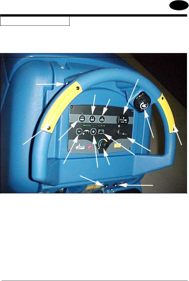
MACHINE CONTROL PANEL
Key Switch (See Figure 1, Item “A”)
The key switch turns “ON” the power to the control panel. “O” is “OFF” and “I” is “ON”.
Traverse Speed Switch (See Figure #1, Item “B”)
The speed control varies from low to high speed. To increase the speed, turn the knob to the right. To decrease the speed, turn the knob to the left.
One Touch Control Button (See Figure 1, Item “C”)
The one touch control button raises and lowers the brush head assembly, starts and stops the vacuum motor automatically. Press the one touch control button once and the brush head assembly lowers to the floor and the vacuum motor turns “ON” (brush head and vacuum LEDs illuminate green). The brush motors start when the brushes are down and the forward palm button is depressed. Press the one touch control button again and the brush head assembly raises, the vacuum motor will remain on for 10 seconds and then shut “OFF”.
Increase Brush Pressure Button (See Figure 1, Item D)
This button is used to increase the brush pressure. Increased brush pressure may be required when stripping or cleaning heavily soiled floors. To increase brush pressure, first lower the brushes by pressing the one touch control button (Item “C”). This will lower the brushes to the normal scrub position. To increase brush pressure, press the button (Item “D”). The LED above the button will illuminate yellow. Press the button (Item “D”) again and the brushes will return to normal scrub (yellow LED will turn “OFF”). NOTE: Increase brush pressure is not available on cylindrical machine.
Vacuum Motor Button (See Figure 1, Item “E”)
The vacuum motor button turns the vacuum motor “ON” or “OFF”, regardless of brush head assembly position. The green LED will illuminate when the vacuum motor is “ON”.
Solution Control Buttons (See Figure 1, Item “F & G”)
The solution control buttons regulate the flow of cleaning solution to the floor. The normal scrub solution setting is indicated by two green bars on the meter. On cylindrical machines, with most floor conditions, the solution setting should be set one step higher. To increase the flow, press the solution flow button “G” (+) until the desired flow is reached. To decrease the flow, press the solution flow button “F” (-) until the desired flow is reached. To shut off the solution, press the solution flow button “F” (-) until no indicators are visible on the display. NOTE: No solution will flow when the machine does not traverse.
Forward Palm Buttons (See Figure 1, Item “H”)
The forward palm buttons turn the traverse motor “ON” and if the brush motors are in the down position, it also activates the brush motors and solution control module. Either the right or the left palm button can be used.
Reverse Push Button (See Figure 1, Item “I”)
The reverse push button, when used in conjunction with one of the forward palm buttons, causes the machine to reverse direction. The reverse speed is 67% of the forward speed.
Charge / Battery Meter (See Figure 1, Item “J”)
The charge / battery meter indicates the battery is being charged when the charger is plugged into an AC outlet. It also indicates the amount of charge that is left in the batteries while the machine is in use. When the charge gets too low the brush/pad motors will shut off.
Circuit Breakers (See Figure 1, Item “K & L”)
The circuit breakers for the brush motors are located on the control panel. If a circuit breaker trips, determine which motor is not operating and turn the key switch “OFF”. Wait five minutes and push the reset button back in. Turn the key switch “ON”, and try again. An authorized service person should be contacted if the breaker trips again.
Hour Meter (Optional) (See Figure 1, Item “M”)
The hour meter indicates the number of hours the machine has operated. It runs only when the machine is moving forward or reverse.
Chemical Mixing Control (Optional) (See Figure 1, Item “N”)
The chemical mixing control regulates the amount of concentration of cleaning chemical mixed with the clear water from the solution tank. Turning the chemical mixing knob clockwise increases the concentration of chemical.
-8- FORM NO. 71492A |
Nilfisk ALTO Operator’s Manual (EN) - SCRUBTEC 866, 871, 866, Boost 8 and 871C |
ENGLISH EN
MACHINE CONTROL PANEL
M
I
D
E
H C B
J
A H
F K G N
L
Figure 1
Nilfisk ALTO Operator’s Manual (EN) - SCRUBTEC 866, 871, 866, Boost 8 and 871C |
FORM NO. 71492A - 9 - |

ENGLISH EN
MACHINE CONTROLS AND FEATURES
Squeegee Lift Handle (Manual Squeegee Lift) (See figure 2)
The squeegee lift handle is located below the control handles in the center. It is used to raise or lower the squeegee.
Float Shut Off (See Figure 3).
The shut-off switch for the vac motor is located in the recovery tank. It automatically turns off the vac motor when the recovery tank is full.
HOW TO PREPARE THE MACHINE
FOR OPERATION
How To Install The Batteries
This machine uses four - 6 volt batteries. The batteries are located in the battery compartment under the recovery tank.
To install the batteries, follow this procedure:
1.Turn machine off. Set brake (if equipped).
2.Make sure recovery tank is empty.
3.Tip up the recovery tank to it’s full open position. See figure 4.
CAUTION: |
Before raising the tank, be sure tank is |
|
empty. |
WARNING: |
Do not operate the machine while the |
|
recovery tank is in the open position. The |
|
tank can be accidentally bumped and it may |
|
slam shut. |
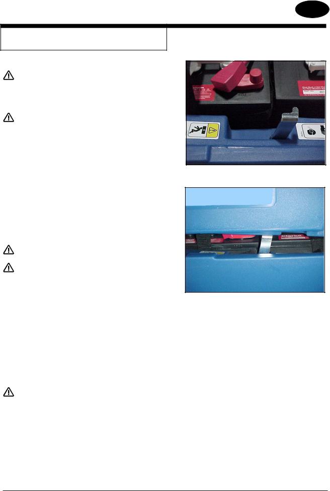
4.Place the batteries in the tray as shown in Figure 5.
WARNING: |
The batteries are heavy. Lifting batteries |
|
without help could result in an injury. Get |
|
help to lift the batteries. |
WARNING: |
Working with batteries can be dangerous. |
|
Always wear eye protection and protective |
|
clothing when working near batteries. NO |
|
SMOKING! |
5.Connect the cables between batteries and install battery cable assembly as indicated. See figure 5.
6.Join the connector from the battery pack to the connector on the control panel.
7.Close recovery tank by slowly lowering the tank.
WARNING: |
Never charge any battery with an unsuitable |
|
battery charger. Carefully follow the instruc- |
|
tions by the manufacturer of the batteries |
|
and battery charger. |
Figure 2
Figure 3
Figure 4
FRONT
Figure 5
-10- FORM NO. 71492A |
revised 9/10 |
Nilfisk ALTO Operator’s Manual (EN) - SCRUBTEC 866, 871, 866, Boost 8 and 871C |
ENGLISH EN
HOW TO PREPARE THE MACHINE
FOR OPERATION
How to program battery charger (WET or AGM batteries):
According to the type of batteries (WET or AGM), set the machine and electronic board of the battery charger as follows:
Charger Setting
1.Turn the key switch “ON” (see figure 5A, item A) and in the very first seconds of machine operation pay attention to the following:
•If the green warning light (item B) is flashing, the charger is set to AGM.
•If the yellow warning light (item C) is flashing, the charger is set to GEL EXIDE.
•If the red warning light (item D) is flashing, the charger is set to WET.
2.If the setting is to be changed, perform the following procedure: a. Turn the key switch “OFF”.
b. Press and hold the buttons (items E and F) at the same time, then turn the key switch (item A) “ON”.
c. Continue to hold the buttons (items E and F) until the battery meter LED light turns “ON” and “OFF” and then release both buttons.
d. Within 3 seconds, toggle the button (item F) to advance the green bar (item G) to the desired charger setting (see green bar position for charger settings below):
Green bar setting (item G)
•1st green bar - WET @ 25 amps, 250 & 330 ah batteries (4 RED blinks).
•2nd green bar - GEL/AGM @ 25 amps, 260 & 312 AGM (4 GREEN blinks).
•3rd green bar - GEL EXIDE @ 25 amps (4 YELLOW blinks).
•4th green bar - WET @ 15 amps (2 RED blinks).
•5th green bar - GEL/AGM @ 15 amps (2 GREEN blinks).
•6th green bar - GEL EXIDE @ 15 amps (2 YELLOW blinks).
e.Once proper battery charger profile is selected, wait until battery LED light quits flashing and stays on before turning key switch “OFF”.
f.Repeat step 1 to verify that proper charger profile was programmed for battery type (WET or GEL).
NOTE: Charge the batteries before using the machine.
E F
G
D C B A
Figure 5A
Nilfisk ALTO Operator’s Manual (EN) - SCRUBTEC 866, 871, 866, Boost 8 and 871C |
FORM NO. 71492A - 11 - |

ENGLISH EN
HOW TO PREPARE THE MACHINE
FOR OPERATION
Battery Maintenance
The electrical power to operate the machine comes from the storage batteries. Storage batteries need preventative maintenance.
WARNING: |
Working with batteries can be dangerous. |
|
Always wear eye protection and protective |
|
clothing when working near batteries. NO |
|
SMOKING! |
To maintain the batteries in good condition, follow these instructions:
1.Keep the electrolyte at the correct level. The correct level is between 1/4” (1/2 cm) below the bottom of the tube in each cell and above the tops of the plates. Check the level of the electrolyte each time you charge the batteries. See figure 6.
NOTE: Check the level of electrolyte prior to charging the batteries. Be sure the plates in each cell are covered with electrolyte before charging. Do not top off the cells prior to charging the battery. Electrolyte expands during charging. As a result, the electrolyte could overflow from the cells. Always top off the cells with distilled water after charging.
CAUTION: |
Irreversible damage will occur to the batteries if |
|
electrolyte does not cover the plates. Keep the |
|
electrolyte at the correct level. |
CAUTION: |
Machine damage and discharge across the tops of |
|
the batteries can occur if the batteries are over filled. |
|
Do not fill the batteries up to the bottom of the tube |
|
in each cell. Wipe any acid from the machine or the |
|
tops of the batteries. Never add acid to a battery after |
|
installation. |
CAUTION: |
Batteries must be refilled with distilled water only. Do |
|
not use tap water as it may contain contaminants that |
|
will damage batteries. |
2.Keep the tops of the batteries clean and dry. Keep the terminals and connectors clean. To clean the top of the batteries, use a damp cloth with
aweak solution of ammonia or bicarbonate of soda solution. To clean the terminals and connectors, use a terminal and connector cleaning tool. Do not allow ammonia or bicarbonate of soda to get into batteries.
3.Keep the batteries charged.
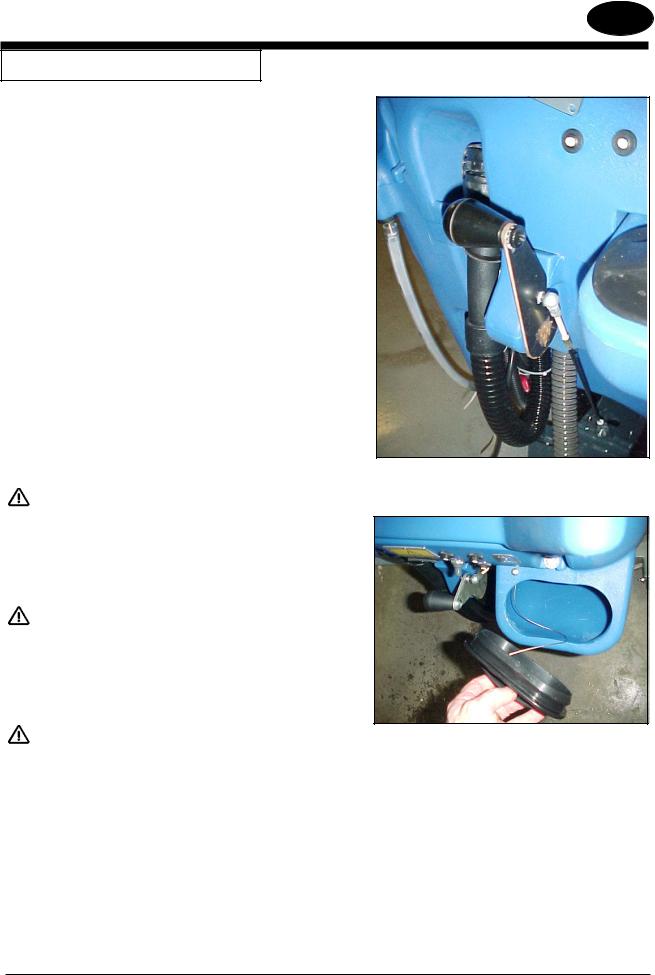
4.To drain battery compartment: (See figure 7)
a.Always wear protective eye protection and protective clothing.
b.Add a weak solution of ammonia or bicarbonate of soda solution to battery compartment to neutralize any spilled acid.
c.Locate drain hose behind the transaxle.
d.Place hand behind flange and open valve.
e.When empty, close valve.
f.Neutralize any acid spills with ammonia or bicarbonate of soda.
Correct Level
Figure 6
Figure 7
-12- FORM NO. 71492A |
Nilfisk ALTO Operator’s Manual (EN) - SCRUBTEC 866, 871, 866, Boost 8 and 871C |
ENGLISH EN
HOW TO PREPARE THE MACHINE
FOR OPERATION
How To Charge The Batteries
WARNING: Charging the batteries in an area without adequate ventilation could result in an explosion. To prevent an explosion, charge the batteries only in an area with good ventilation.
WARNING: Lead acid batteries generate gases which could explode. Keep sparks and flames away from batteries. NO SMOKING!
To charge the batteries, follow this procedure:
1.Make sure the key switch is in the “OFF” position.
2.Before charging the batteries, the battery compartment needs to be vented. To vent compartment, tip up the recovery tank and rotate the tank support bracket, located in the solution tank (see figure 8). Slowly lower the recovery tank and let it rest on the support bracket (see figure 9). To close the tank, lift up on the recovery tank, rotate the support bracket down, then slowly lower the tank to the closed position.
CAUTION: Before raising tank, be sure tank is empty.
WARNING: Do not operate the machine while the recovery tank is in the open position. The tank can be accidentally bumped and it may slam shut.
3.Connect the battery charger AC cord located at the rear of the machine to an appropriate wall receptacle.
4.Observe indicator lights on the charger/battery meter to ensure the charging process has started. Red, yellow and green lights indicate state of charge. Steady on green light indicates the batteries are fully charged.
NOTE: Make sure you plug into a circuit that is not loaded by other equipment. Wall breakers may be tripped and no charge will occur.
WARNING: Never charge any battery with an unsuitable battery charger. Carefully follow the instructions given by the manufacturer of the batteries and battery charger.
NOTE: To prevent permanent damage to the batteries, avoid their complete discharge. Never leave the batteries completely discharged, even if the machine is not being used. When recharging the batteries, keep the recovery tank open. Check the level of the electrolyte and if necessary top off with distilled water.
Figure 8
Figure 9
Nilfisk ALTO Operator’s Manual (EN) - SCRUBTEC 866, 871, 866, Boost 8 and 871C |
revised 9/10 FORM NO. 71492A - 13 - |
ENGLISH EN
HOW TO PREPARE THE MACHINE
FOR OPERATION
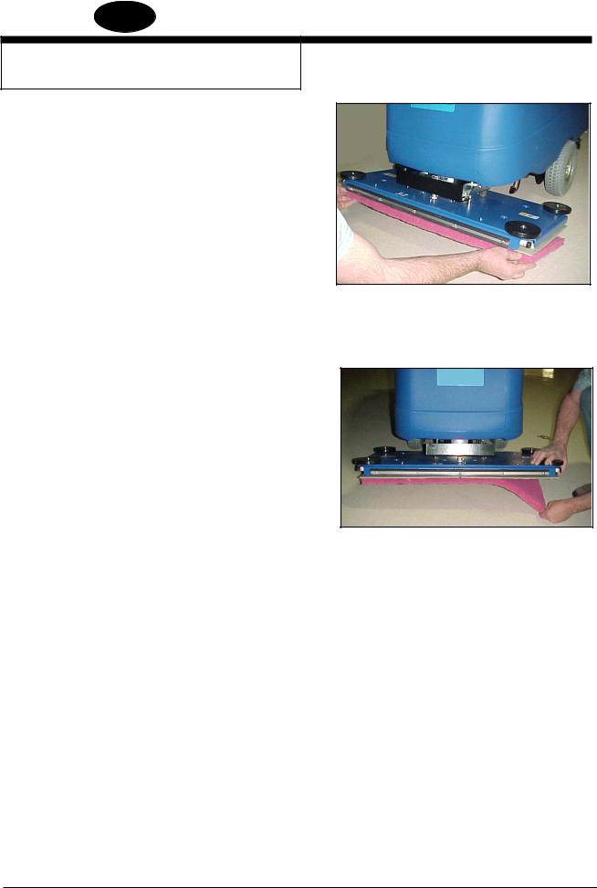
How To Install The Brush Or Pad (BOOST Machine)
To install the brush or pad on the machine, follow this procedure:
1.Turn the key switch “ON”.
2.Put the brush head assembly in the “Up” position.
3.Turn the key switch “OFF”.
4.Go to the front of the machine.
5.Press on a brush or pad, under the flex plates. See figure 10.
NOTE: When using a black pad, position pad on head. Lower head and operate momentarily to affix pad to pad driver (if you have difficulty, position pad on floor and lower head then operate.)
How To Remove The Brush Or Pad (BOOST Machine)
To remove the brush or pad from the machine, follow this procedure:
1.Turn the key switch “ON”.
2.Put the brush head assembly in the “Up” position.
3.Turn the key switch “OFF”.
4.Go to the front of the machine and pull downward on the brush or pad until it releases from the flex plates. See figure 11.
Figure 10
Figure 11
-14- FORM NO. 71492A |
Nilfisk ALTO Operator’s Manual (EN) - SCRUBTEC 866, 871, 866, Boost 8 and 871C |
ENGLISH EN
HOW TO PREPARE THE MACHINE
FOR OPERATION
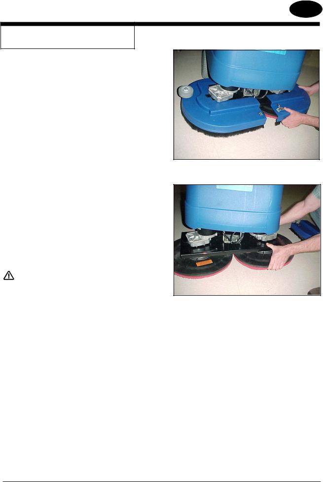
How To Install The Brushes Or Pad Drivers
On The Disc Machine
To install the brushes or pad drivers on the machine, follow this procedure:
1.Turn the key switch “ON”.
2.Put the brush head assembly in the “UP” position.
3.Turn the key switch “OFF”.
4.Unlatch right and left brush housings and remove them. See figure 12.
5.Put a brush or pad driver under the brush motor plate. See figure 13.
6.Align the lugs on the motor gimbal with the slots in the brush gimbal.
7.Pull the brush up until the gimbal locks.
8.Repeat steps 5, 6 and 7 to install the second brush or pad driver.
9.Reinstall right and left brush housings and latch front cover.
DANGER: Operating a machine that is not completely or fully assembled could result in injury or property damage. Do not operate this machine unless it is completely assembled. Inspect the machine carefully before operation.
How To Remove The Brushes Or Pad Drivers
On the Disc Machine
To remove the brushes or pad drivers from the machine, follow this procedure:
1.Turn the key switch “ON”.
2.Put the brush head assembly in the “UP” position.
3.Turn the key switch “OFF”.
4.Unlatch right and left brush housings and remove them. See figure 12.
5.Push down on two sides of the brush or pad driver until the gimbals release.
Figure 12
Figure 13
Nilfisk ALTO Operator’s Manual (EN) - SCRUBTEC 866, 871, 866, Boost 8 and 871C |
FORM NO. 71492A - 15 - |

ENGLISH EN
HOW TO PREPARE THE MACHINE
FOR OPERATION
How To Change Or Reverse Bristle Direction
On Cylindrical Machine
To install or reverse bristle direction on the machine, follow this procedure:
1.Turn the key switch “ON”.
2.Put the brush head assembly in the “UP” position.
3.Turn the key switch “OFF”.
4.Go to the front of the machine and loosen thumb screw on brush door. See figure 14.
5.Lower door approximately 1/2 inch and remove brush door.
6.Remove brush. See figure 15.
7.Inspect brush condition. If damaged or worn, replace it. Otherwise, turn brush end for end periodically to reverse bristle direction for better life.
8.Slide brush onto driver or opposite side and rotate slowly until drive lugs are lined up with brush slots. Push brush all the way in.
9.Install brush door assembly into brush.
10.Raise door and tighten thumb screw.
11 Repeat for the other brush.
DANGER: Operating a machine that is not completely or fully assembled could result in injury or property damage. Do not operate this machine unless it is completely assembled. Inspect the machine carefully before operation.
Figure 14
Figure 15
-16- FORM NO. 71492A |
Nilfisk ALTO Operator’s Manual (EN) - SCRUBTEC 866, 871, 866, Boost 8 and 871C |
ENGLISH EN
HOW TO OPERATE THE MACHINE
How To Operate the Squeegee
The squeegee wipes the floor while the vacuum motor removes the dirty solution from the floor. Use your hand to lower or raise the squeegee handle. To operate the squeegee, follow this procedure:
1.To lower the squeegee rotate the squeegee lever down. See figure 16.
2.To raise the squeegee, rotate the squeegee lever up. See
figure 16.
How to Fill The Solution Tank
1.Remove the solution tank lid. See figure 17.
2.If the machine does not have the Chemical Mixing System, add a cleaning chemical to the solution tank. For the correct amount of chemical, follow the directions shown on the container.
3.Fill the solution tank with water.
4.Replace solution tank lid.
WARNING: |
Water solutions or cleaning materials used |
|
with this type of machine can leave wet ar- |
|
eas on the floor surface. These areas can |
|
cause a dangerous condition for the opera- |
|
tor or other persons. Always put CAUTION |
|
signs near the area you are cleaning. |
WARNING: |
Machines can ignite flammable materi- |
|
als and vapors. Do not use with or near |
|
flammables such as gasoline, grain dust, |
|
solvents, and thinners. Only use a clean- |
|
ing concentration recommended by the |
|
chemical manufacturer. |
WARNING: |
Nilfisk ALTO recommends a maximum |
|
water temperature of 120°F(49°C) |
Figure 16
Figure 17
Nilfisk ALTO Operator’s Manual (EN) - SCRUBTEC 866, 871, 866, Boost 8 and 871C |
FORM NO. 71492A - 17 - |

ENGLISH EN
HOW TO OPERATE THE MACHINE
How To Operate The Chemical Mixing System (Optional)
The chemical mixing system is designed to automatically mix the cleaning chemical directly from the manufacturer’s chemical container into the clear water coming from the solution tank. The chemical control knob on the control panel is used to select the desired ratio according to the recommendation of the chemical manufacturer and the application requirements. The ratio settings are shown in figure 19.
 CAUTION: Do not operate the chemical pump dry. If the chemical container is empty, make sure the chemical control is in the off position.
To operate the chemical mixing system, follow this procedure:
1.Select the proper cleaning chemical for scrubbing application.
2.Set the chemical knob to the recommended setting per the chemical manufacturer.
3.Make sure the recovery tank is empty and then open the recovery tank.
4.Position the manufacturer’s chemical container into the bracket located at the front right side of the solution tank. See figure 18A & 18B
5.Remove container cap and insert bottle adapter and tighten cap.
6.Slowly close the recovery tank.
NOTE: With the knob turned fully counterclockwise, only water will be delivered to the floor.
Figure 18A
Figure 18B
GREEN
BLUE
YELLOW
RED
Figure 19
-18- FORM NO. 71492A |
Nilfisk ALTO Operator’s Manual (EN) - SCRUBTEC 866, 871, 866, Boost 8 and 871C |

ENGLISH EN
HOW TO OPERATE THE MACHINE
 WARNING: Water solutions or cleaning materials used with this type of machine can leave wet areas on the floor surface. These areas can cause a dangerous condition for the operator or other persons. Always put CAUTION signs near the area you are cleaning.
B
WARNING: Machines can ignite flammable materials and vapors. Do not use with or near flammables such as gasoline, grain dust, solvents and thinners. Only use a cleaning concentration recommended by the chemical manufacturer.
 WARNING: Nilfisk ALTO recommends a maximum water temperature of 120oF (49oC).
Operating The Machine
NOTE: Put the machine in the lowest traverse speed setting. Use the machine in an area that has no furniture or objects until you can do the following:
1.Move the machine in a straight direction, forward and backward.
2.Stop the machine safely.
3.Turn the machine both left and right and return to a straight direction.
To move the machine, follow this procedure:
1.Release the parking brake (if equipped with machine).
2.Turn the key switch to the “ON” position
3.Raise the brush.
4.Raise the squeegee.
5.When either the left or right forward palm buttons (figure 20, item A) are pushed in, the machine will go forward.
6.Control the speed of traverse by using the traverse speed control knob (figure 20, item C).
7.To stop, release the forward palm buttons.
8.To reverse the machine, push in the white reverse switch (figure 20 item B) and either the right or left forward palm buttons (figure 20 item A) at the same time.
9.To stop, release the forward palm buttons.
10.To turn the machine, push the rear of the machine to the side.
11.When you stop the machine, turn the key switch “OFF”, remove the key and set the parking brake (if equipped).
A
A C
Figure 20
Nilfisk ALTO Operator’s Manual (EN) - SCRUBTEC 866, 871, 866, Boost 8 and 871C |
FORM NO. 71492A - 19 - |

ENGLISH EN
HOW TO OPERATE THE MACHINE
How To Clean A Floor
 WARNING: Water solutions or cleaning materials used with this type of machine can leave wet areas on the floor surfaces. These areas can cause a dangerous condition for the operator or other persons. Always put CAUTION signs near the area you are cleaning.
To clean a floor, follow this procedure:
1.Set the parking brake (if equipped with machine.)
2.Put the water and a cleaning chemical in the clean solution tank.
3.Release the parking brake (if equipped with machine.)
4.Turn the key switch “ON”.
5.Lower the squeegee.
6.Press the one touch control button to lower the brush head assembly and start vacuum motor.
7.Adjust the flow of clean solution to the flow desired.
8.Move the machine across the floor in the forward direction.
9.Make a 180° turn.
NOTE: When you make more passes across the floor, let the brush clean approximately 2 inches (5 cm) of the area already cleaned by the brush.
NOTE: During most cleaning procedures, apply and remove the solution in one operation.
How To Clean A Very Dirty Floor
To clean a very dirty floor, follow this procedure:
1.Apply solution to the floor.
2.Do not lower the squeegee. Shut vacuum motor “OFF”.
3.Lower the brush or pad and scrub the floor.
4.Scrub the floor again with additional solution and lower the squeegee and turn vacuum motor “ON”.
5.Pick up all the solution with the squeegee.
-20- FORM NO. 71492A |
Nilfisk ALTO Operator’s Manual (EN) - SCRUBTEC 866, 871, 866, Boost 8 and 871C |
ENGLISH EN
MAINTENANCE
 WARNING: Maintenance and repairs must be done by authorized personnel only.
 WARNING: Always empty the solution tank and recovery tank before doing any maintenance.
 WARNING: Keep all fasteners tight.
These Maintenance Procedures Must Be Done Every Day
Keep the machine clean, it will need fewer repairs and have longer life.
Do These Procedures When You Begin Your Work Period |
Figure 21 |
|
1.Turn off key switch.
2.Disconnect AC power from battery charger (follow charger instructions).
3.Make sure the screen filter over the vacuum motor is clean and in position (see figure 21.
4.Make sure the valve on the recovery drain hose is clean. Tightly close the valve.
5.Make sure the brushes are in position and installed correctly
6.Check the installation of the squeegee and squeegee hose.
7.Make sure the solution drain/level indicator hose is secure on upper fitting.
Nilfisk ALTO Operator’s Manual (EN) - SCRUBTEC 866, 871, 866, Boost 8 and 871C |
FORM NO. 71492A - 21 - |
 Loading...