


TerraTM 28B
SERVICE MANUAL
Advance model: 908 4702 010
1463163000(1)2007-02

ENGLISH |
SERVICE MANUAL |
1463163000(1)2007-02 |
TerraTM 28B |

SERVICE MANUAL |
ENGLISH |
GENERAL INFORMATION ......................................................................................................................................... |
2 |
CONVENTIONS ..................................................................................................................................................... |
2 |
MACHINE LIFTING ................................................................................................................................................ |
2 |
MACHINE TRANSPORT ....................................................................................................................................... |
2 |
OTHER AVAILABLE MANUALS ............................................................................................................................ |
2 |
SAFETY ................................................................................................................................................................. |
3 |
GENERAL INSTRUCTIONS .................................................................................................................................. |
3 |
TECHNICAL DATA ................................................................................................................................................. |
4 |
MAINTENANCE ..................................................................................................................................................... |
5 |
SCHEDULED MAINTENANCE TABLE .................................................................................................................. |
5 |
MACHINE NOMENCLATURE ................................................................................................................................ |
6 |
SWEEPING SYSTEM ................................................................................................................................................. |
7 |
SIDE BROOM HEIGHT CHECK AND ADJUSTMENT ........................................................................................... |
7 |
SIDE BROOM DISASSEMBLY/ASSEMBLY .......................................................................................................... |
8 |
MAIN BROOM HEIGHT CHECK AND ADJUSTMENT .......................................................................................... |
9 |
MAIN BROOM DISASSEMBLY/ASSEMBLY ....................................................................................................... |
10 |
MAIN MOTOR-TO-IDLER GEAR BELT DISASSEMBLY/ASSEMBLY (FOR MAIN BROOM) ............................. |
11 |
MAIN BROOM BELT DISASSEMBLY/ASSEMBLY .............................................................................................. |
12 |
SIDE BROOM MOTOR ELECTRICAL INPUT CHECK ....................................................................................... |
13 |
SIDE BROOM MOTOR DISASSEMBLY/ASSEMBLY .......................................................................................... |
14 |
TROUBLESHOOTING ......................................................................................................................................... |
15 |
SKIRT ....................................................................................................................................................................... |
16 |
SKIRT HEIGHT AND OPERATION CHECK ........................................................................................................ |
16 |
LEFT SIDE SKIRT DISASSEMBLY/ASSEMBLY ................................................................................................. |
17 |
RIGHT SIDE SKIRT DISASSEMBLY/ASSEMBLY ............................................................................................... |
18 |
REAR SKIRT DISASSEMBLY/ASSEMBLY ......................................................................................................... |
19 |
FRONT SKIRT DISASSEMBLY/ASSEMBLY ....................................................................................................... |
19 |
DUST AND DEBRIS COLLECTION SYSTEM ......................................................................................................... |
20 |
DUST FILTER CLEANING AND INTEGRITY CHECK, HOPPER GASKET CHECK .......................................... |
20 |
FILTER SHAKER OPERATION CHECK .............................................................................................................. |
21 |
VACUUM SYSTEM MOTOR ELECTRICAL INPUT CHECK ............................................................................... |
22 |
VACUUM SYSTEM MOTOR DISASSEMBLY/ASSEMBLY ................................................................................. |
23 |
TROUBLESHOOTING ......................................................................................................................................... |
23 |
DRIVE SYSTEM ....................................................................................................................................................... |
24 |
DRIVE SYSTEM CONTROL CABLE ADJUSTMENT .......................................................................................... |
24 |
DRIVING BELT DISASSEMBLY/ASSEMBLY ...................................................................................................... |
25 |
TROUBLESHOOTING ......................................................................................................................................... |
26 |
MAIN MOTOR ........................................................................................................................................................... |
27 |
DRIVING BELT AND CLUTCH VISUAL INSPECTION AND ADJUSTMENT ...................................................... |
27 |
MAIN MOTOR ELECTRICAL INPUT CHECK ..................................................................................................... |
28 |
MAIN MOTOR CARBON BRUSH CHECK AND REPLACEMENT ...................................................................... |
29 |
MAIN MOTOR DISASSEMBLY/ASSEMBLY ........................................................................................................ |
30 |
TROUBLESHOOTING ......................................................................................................................................... |
32 |
OTHER SYSTEMS ................................................................................................................................................... |
33 |
NUT AND SCREW TIGHTENING CHECK .......................................................................................................... |
33 |
HOOD DISASSEMBLY/ASSEMBLY .................................................................................................................... |
34 |
SIDE BROOM COVER DISASSEMBLY/ASSEMBLY .......................................................................................... |
35 |
ELECTRICAL SYSTEM ............................................................................................................................................ |
36 |
BATTERY CHARGER CABLE INTEGRITY CHECK ........................................................................................... |
36 |
BATTERY CHARGING ........................................................................................................................................ |
37 |
BATTERY DISASSEMBLY/ASSEMBLY ............................................................................................................... |
38 |
HOOD SAFETY SWITCH OPERATION CHECK ................................................................................................. |
38 |
LAMELLAR FUSE CHECK/REPLACEMENT ...................................................................................................... |
39 |
TROUBLESHOOTING ......................................................................................................................................... |
40 |
COMPONENT LAYOUT ....................................................................................................................................... |
41 |
WIRING DIAGRAM .............................................................................................................................................. |
42 |
TerraTM 28B 1463163000(1)2007-02 |
|

ENGLISH |
SERVICE MANUAL |
GENERAL INFORMATION
CONVENTIONS
Forward, backward, front, rear, left or right are intended with reference to the operator’s position, that is to say with the hands on the handlebar.
MACHINE LIFTING
WARNING!
Do not work under the lifted machine without supporting it with safety stands.
MACHINE TRANSPORTATION
WARNING!
Before transporting the machine, make sure that:
–All guards and hoods are closed
–The machine is off
–The machine is securely fastened to the means of transport.
OTHER AVAILABLE MANUALS
The following manuals are available at Advance Literature Service Department:
–Terra 28B, Spare Parts List – Advance Form Number 146 3086 000
–Terra 28B, User Manual – Advance Form Number 146 3081 000
SAFETY
The following symbols indicate potentially dangerous situations. Always read this information carefully and take all necessary precautions to safeguard people and property.
DANGER!
It indicates a dangerous situation with risk of death for the operator.
WARNING!
It indicates a potential risk of injury for people.
CAUTION!
It indicates a caution or a remark related to important or useful functions. Pay particular attention to the paragraphs marked by this symbol.
NOTE
It indicates the necessity to refer to the User Manual before performing any procedure.
CONSULTATION
It indicates that it is necessary to consult the User Manual before performing any procedure.
|
1463163000(1)2007-02 |
TerraTM 28B |

SERVICE MANUAL |
ENGLISH |
GENERAL INFORMATION
GENERAL SAFETY PRECAUTIONS
Specific warnings and cautions to inform about potential damages to people and machine are shown below.
DANGER!
–Before performing any maintenance/repair procedure, turn the main switch to “0”.
–Before performing any maintenance/repair procedure on electrical components, disconnect the battery negative terminal.
–This machine must be used by properly trained and authorised personnel only. Children or disabled people cannot use this machine.
–Do not wear jewerly when working near electrical components.
–Keep the battery away from sparks, flames and incandescent material.
–Do not work under the lifted machine without supporting it with safety stands.
–Do not operate the machine near toxic, dangerous, flammable and/or explosive powders, liquids or vapours.
WARNING!
–Carefully read all the instructions before carrying out any maintenance/repair procedure.
–Before using the battery charger, ensure that frequency and voltage values, shown on the machine serial number plate, match the electrical mains voltage.
–Do not pull or carry the machine by the battery charger cable and never use the battery charger cable as a handle. Do not close a door on the battery charger cable, or pull the battery charger cable around sharp edges or corners. Do not run the machine on the battery charger cable.
–Keep the battery charger cable away from heated surfaces.
–Do not charge the batteries if the battery charger cable or the plug are damaged.
–If the battery charger cable is damaged, replace it.
–To reduce the risk of fire, electric shock, or injury, do not leave the machine unattended when it is plugged in.
Before performing any maintenance procedure, disconnect the battery charger cable from the electrical mains.
–Always protect the machine against the sun, rain and bad weather, both under operation and inactivity condition. Store the machine indoors, in a dry place.
–Do not allow to be used as a toy. Close attention is necessary when used near children.
–Use only as shown in this Manual. Use only Advance recommended accessories.
–Take all necessary precautions to prevent hair, jewerly and loose clothes from being caught by the machine moving parts.
–Do not leave the machine unattended if the main switch is not turned to “0” and without being sure that it cannot move independently.
–Do not wash the machine with direct or pressurised water jets, or with corrosive substances. Do not use compressed air to clean this type of machine.
–While using this machine, take care not to cause warm to other people, and children especially.
–The machine storage temperature must be between 0°C and +40°C.
–The machine working temperature must be between 0°C and +40°C.
–The humidity must be between 30% and 95%.
–Do not use the machine as a means of transport.
–Do not use the machine on slopes with a gradient exceeding the specifications.
–Do not allow the brooms to operate while the machine is stationary to avoid damaging the floor.
–In case of fire, possibly use a powder fire extinguisher, not a water one.
–Do not bump into shelves or scaffoldings, especially where there is a risk of falling objects.
–Adjust the operation speed to suit the floor conditions.
–This machine cannot be used on roads or public streets.
–Do not remove or modify the plates affixed to the machine.
–Do not tamper with the machine safety guards and follow the ordinary maintenance instructions scrupulously.
–If the machine is used according to the instructions, the vibrations are not dangerous. The machine vibration level is less than 2.5 m/s2 (98/37/EEC-EN 1033/1995).
–Carefully read all the instructions before carrying out any maintenance/repair procedure.
–To ensure machine proper and safe operation, perform the scheduled maintenance shown in the relevant chapter of this Manual.
–If parts must be replaced, require ORIGINAL spare parts from a Dealer or Authorised Retailer.
–The machine must be disposed of properly, because of the presence of toxic-harmful materials (batteries, plastics, etc.), which are subject to standards that require disposal in special centers (see Scrapping chapter in the User
Manual).
TerraTM 28B |
1463163000(1)2007-02 |
|
ENGLISH |
SERVICE MANUAL |
|
GENERAL INFORMATION |
|
|
TECHNICAL DATA |
|
|
|
|
|
General |
|
Values |
|
|
|
Cleaning width (without side broom) |
19.7 in (500 mm) |
|
|
|
|
Cleaning width (with side broom) |
28.3 in (720 mm) |
|
|
|
|
Machine size with folded handlebar and without side broom (length x width x height) |
39.3 x 31.4 x 19.7 in (998 x 797 x 501 mm) |
|
|
|
|
Minimum distance from the ground (skirts not included) |
1.0 in (25 mm) |
|
|
|
|
Main broom size (diameter x length) |
7.9 x 19.7 in (200 x 500 mm) |
|
|
|
|
Side broom diameter |
|
12.4 in (315 mm) |
|
|
|
Main broom speed |
|
335 rpm |
|
|
|
Side broom speed |
|
100 rpm |
|
|
|
Gradeability |
|
2% |
|
|
|
Hopper capacity |
|
15.8 US gal (60 litres) |
|
|
|
Total machine weight with standard battery |
167.5 lb (76 kg) |
|
|
|
|
Front steering wheel size (diameter x length) |
3.0 x 1.3 in (75 x 32 mm) |
|
|
|
|
Rear wheel size (diameter x length) |
11.8 x 1.8 in (300 x 45 mm) |
|
|
|
|
Maximum drive speed |
|
2.3 miles/h (3.7 km/h) |
|
|
|
Sound pressure level at workstation (A Lpa) |
59.3 dB(A) |
|
|
|
|
|
|
|
Electrical components |
Values |
|
|
|
|
Electrical system voltage |
12 V |
|
|
|
|
Standard battery |
|
GEL, 12 V, 77 Ah |
|
|
|
Battery charger |
|
6 A |
|
|
|
Main motor |
|
200 W, 1,500 rpm |
|
|
|
Side broom motor |
|
40 W |
|
|
|
Vacuum system motor |
|
50 W |
|
|
|
|
|
|
Dust vacuuming and filtering |
Values |
|
|
|
|
Dust filter |
|
5-10 µm |
|
|
|
Dust filter surface |
|
10.8 ft2 (1 m2) |
Main broom compartment vacuum |
0.24 in H2O (6.2 mm H2O) |
|
|
|
|
|
1463163000(1)2007-02 |
TerraTM 28B |

SERVICE MANUAL |
ENGLISH |
GENERAL INFORMATION
MAINTENANCE
The lifespan of the machine and its maximum operating safety are ensured by correct and regular maintenance.
The following table provides the scheduled maintenance. The intervals shown may vary according to particular working conditions, which are to be defined by the person in charge of the maintenance.
The following paragraphs give further instructions about maintenance procedures listed in the Scheduled Maintenance Table.
NOTE
To perform maintenance procedures, the machine must be off and, if necessary, the batteries must be disconnected.
Moreover, carefully read the instructions in the Safety paragraph.
SCHEDULED MAINTENANCE TABLE
Procedure |
Every 10 |
Every 50 |
Every 200 |
Every 400 |
|
|
|
hours |
hours |
hours |
hours |
|
|
|
|
|
|
Battery charger cable check |
|
|
|
|
|
|
|
|
|
|
|
Side and main broom height check and adjustment |
|
|
|
|
|
|
|
|
|
|
|
Skirt height and operation check |
|
|
|
|
|
|
|
|
|
|
|
Dust filter cleaning and integrity check |
|
|
|
|
|
|
|
|
|
|
|
Hopper gasket check |
|
|
|
|
|
|
|
|
|
|
|
Filter shaker operation check |
|
|
|
|
|
|
|
|
|
|
|
Drive belt and clutch visual inspection |
|
|
|
|
|
|
|
|
|
|
|
Drive system belt tensioner adjustment |
|
|
|
|
|
|
|
|
|
|
|
Nut and screw tightening check |
|
|
(1) |
|
|
|
|
|
|
|
|
Motor carbon brush check or replacement |
|
|
|
|
|
|
|
|
|
|
|
(1): |
And after the first 8 hours. |
|
|
|
|
TerraTM 28B |
1463163000(1)2007-02 |
|

ENGLISH |
SERVICE MANUAL |
GENERAL INFORMATION
MACHINE NOMENCLATURE
Throughout this manual you will find numbers in brackets – for example: (2). These numbers refer to the components shown in these two nomenclature pages. Refer to these pages whenever it is necessary to identify a component mentioned in the text.
1.Main switch for vacuum system, main broom and side broom activation
2.Charged battery warning light (green)
3.Semi-discharged battery warning light (yellow)
4.Discharged battery warning light (red)
5.Drive control lever
6.Handlebar
7.Handlebar adjusting knobs
8.Filter shaker knob
9.Hopper
10.Front steering wheel
11.Side broom
12.Side broom lifting/lowering lever
13.Side broom height adjusting knob
14.Main broom
15.Main broom height adjusting knobs
16.Rear driving wheels
17.Can holder
18.Battery charger cable
19.Battery charger cable housing
20.Side broom motor circuit breaker
21.Main motor circuit breaker
22.Battery
23.Dust filter
24.Side broom motor
25.Main motor
26.Drive system gear (clutch)
27.Vacuum fan
28.Battery charger - Function control
29.Vacuum system motor lamellar fuse (7.5 A)
30.Hood
31.Hopper upper handle
32.Hopper lower handles
33.Serial number plate/technical data/conformity certification
34.Side skirts
35.Front skirt
36.Rear skirt
37.Side broom cover
38.Drive system control cable adjuster
1
2
3
4
6
|
5 |
|
|
|
|
|
|
|
|
|
38 |
7 |
17 |
15 |
|
|
|
|
20 19 18 |
|
|
|
|
31 |
|
|
|
21 |
|
|||
7 |
|
|
8 |
16 |
22 |
33 |
|
|
24 |
|
|
|
|
27 |
23 |
||||||
|
|
14 |
|
|
|
|||||
30 |
36 |
|
9 |
|
|
|
25 |
|
|
|
|
34 |
|
|
|
|
|
|
|||
|
|
|
|
|
|
|
|
|
||
|
|
|
|
|
|
|
|
|
|
|
16 |
35 |
|
29 |
|
|
|
15 12 |
|
|
|
|
37 |
|
|
|
32 |
28 |
|
||
34 |
|
|
|
|
26 |
|
13 |
|
11 |
10 |
|
38 |
|
|
|
|
|
|
S301584 |
|
|
|
|
|
|
|
|
1463163000(1)2007-02 |
TerraTM 28B |
|
|
|
||
SERVICE MANUAL |
ENGLISH |
SWEEPING SYSTEM
SIDE BROOM HEIGHT CHECK AND ADJUSTMENT
NOTE
Brooms of various hardness are available. This procedure is applicable to all types of brooms.
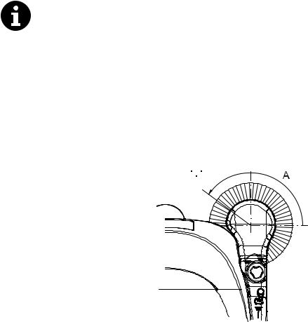
1.Check that the side broom is at the correct distance from the ground, according to the following procedure:
•Drive the machine on a level ground and lower the side broom.
•Keep the machine stationary and turn on the side broom for a few seconds.
•Turn off the side broom by pressing the switch (1), then lift it and move the machine.
•Check if the size and orientation of the print left by the side broom are as shown in the figure (A, Fig. 1): the side broom must touch the ground along a circle arc ranging from “10 o’clock” position to “3 o’clock” position.
•If the print is not within specifications, it is necessary to adjust the broom height, according to the procedure shown in step 2.
2.Turn the knob (13) clockwise or counter-clockwise to adjust the broom height up or down.
3.Perform step 1 again to check that the side broom is at the correct distance from the ground.
4.When the broom is too worn and can no longer be adjusted, replace it according to the procedure shown in the relevant paragraph.
 10
10
 3
3
S301585
TerraTM 28B |
1463163000(1)2007-02 |
|

ENGLISH |
SERVICE MANUAL |
SWEEPING SYSTEM
SIDE BROOM DISASSEMBLY/ASSEMBLY
NOTE
Brooms of various hardness are available. This procedure is applicable to all types of brooms.
CAUTION!
It is advisable to use protective gloves when replacing the side brooms because there can be sharp debris between the bristles.
Disassembly
1.Drive the machine on a level ground.
2.Turn the main switch (1) to “0”.
3.Lift the side broom.
4.Loosen the knob (A) inside the side broom, then remove the broom (B) by disengaging it from the pins (C).
Assembly
5.Install the new broom on the machine engaging it on the pins (C), then tighten the knob (A).
6.Adjust the height of the new broom according to the procedure shown in the previous paragraph.
B C
A
S301586
|
1463163000(1)2007-02 |
TerraTM 28B |
SERVICE MANUAL |
ENGLISH |
SWEEPING SYSTEM
MAIN BROOM HEIGHT CHECK AND ADJUSTMENT
NOTE
Brooms of various hardness are available. This procedure is applicable to all types of brooms.
1.Check that the main broom is at the correct distance from the ground, according to the following procedure:
•Drive the machine on a level ground.
•Keep the machine stationary and turn on the main broom for a few seconds.
•Turn off the main broom by pressing the switch (1), then move the machine.
•Check that the main broom print (A), along its length, is 1.2-2 in (3-5 cm) wide.
•If the print is not within specifications, it is necessary to adjust the broom height, according to the procedure shown in step 2.
2.Turn the main switch (1) to “0”.
3.On both sides of the machine, loosen the knob (B).
4.Grasp the support (C) on the points (D) and move it upwards, then lift it or lower it to change the main broom height. For height variation, refer to the indicator (E). Then tighten the knob (B) on both sides of the machine.
5.Perform step 1 again to check that the main broom is at the correct distance from the ground.
6.When the broom is too worn and can no longer be adjusted, replace it according to the procedure shown in the relevant paragraph.
CAUTION!
An excessive print (larger than 5 cm) of the main broom can lead to machine malfunction and overheating of moving and electric parts, thus reducing machine life.
Pay careful attention when performing the above-mentioned checks, and always use the machine according to the indicated conditions.
D
B
E
1.2 in - 2 in |
|
|
3 cm - 5 cm |
C |
D |
|
S301587
TerraTM 28B |
1463163000(1)2007-02 |
|
ENGLISH |
SERVICE MANUAL |
SWEEPING SYSTEM
MAIN BROOM DISASSEMBLY/ASSEMBLY
NOTE
Brooms of various hardness are available. This procedure is applicable to all types of brooms.
CAUTION!
It is advisable to use protective gloves when replacing the main broom because there can be sharp debris between the bristles.
1.Drive the machine on a level ground.
2.Turn the main switch (1) to “0”.
3.Remove the hopper (9).
4.Completely loosen the handwheels (A) on the left side of the machine.
5.Remove the lid (B) by grasping it on the points (C).
6.Grasp the main broom (D) on the points (E) and (F), then disconnect it from the drive hub (G) by pulling it in the direction shown by the arrow (H); then remove it in the direction shown by the arrow (I).
7.Install the new main broom with the bristles rows (D) bent as shown in the figure.
8.Install the new broom by performing steps 3 to 6 in the reverse order.
9.Adjust the main broom height according to the procedure shown on the relevant page.
B C
A
F D
I
G 


 H
H
E
S301588
10 |
1463163000(1)2007-02 |
TerraTM 28B |
SERVICE MANUAL |
ENGLISH |
SWEEPING SYSTEM
MAIN MOTOR-TO-IDLER GEAR BELT DISASSEMBLY/ASSEMBLY (FOR MAIN BROOM)
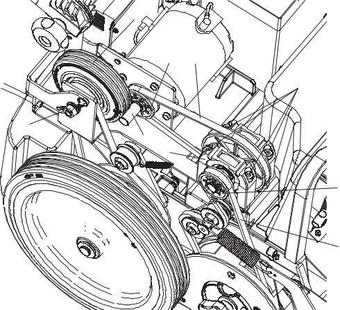
Disassembly
1.Remove the hood (see the procedure in the relevant paragraph).
2.Loosen the nut (A) and move away the clutch (B) from the crankshaft (H).
3.Manually disengage the belt (C) from the pulley (D).
4.Remove four screws (E), then remove the idler gear assembly (F) and the belt (G) by disengaging it from the pulley (I).
Assembly
5.Perform steps 2 to 4 in the reverse order.
6.Visually inspect and adjust the driving belts and clutch (see the procedure in the relevant paragraph).
7.Install the hood (see the procedure in the relevant paragraph).
B
I G
E
A
H F
D
C
S301589
TerraTM 28B |
1463163000(1)2007-02 |
11 |
ENGLISH |
SERVICE MANUAL |
SWEEPING SYSTEM
MAIN BROOM BELT DISASSEMBLY/ASSEMBLY
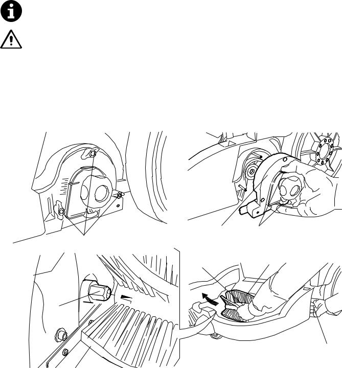
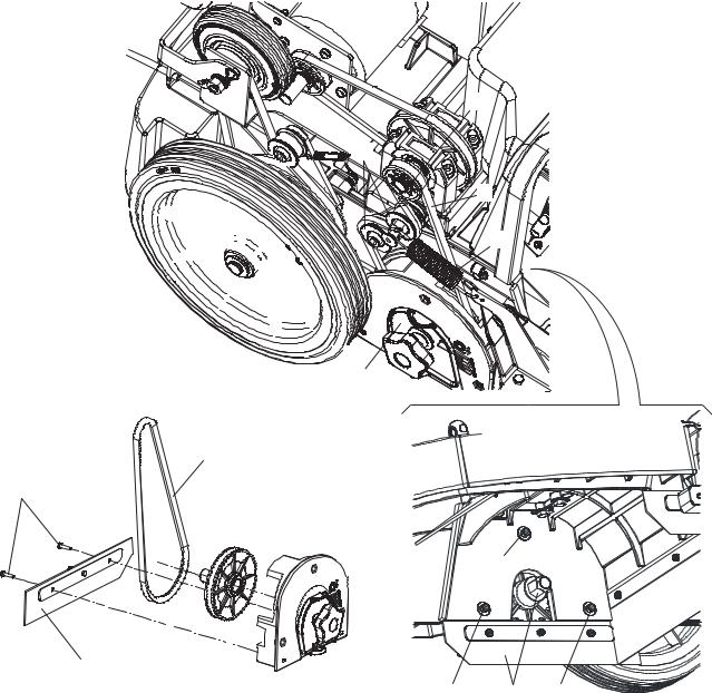
Disassembly
1.Remove the hood (see the procedure in the relevant paragraph).
2.Remove the main broom (see the procedure in the relevant paragraph).
3.Manually disengage the belt (A) from the pulley (B).
4.Remove the screws (C), then remove the right lid (D) and the main broom belt.
5.At the workbench, remove the screws (I) and the skirt (E), then remove the main broom belt (F).
6.Check the tensioner (G) and the spring (H) for proper operation.
Assembly
7.Perform steps 3 to 5 in the reverse order.
8.Visually inspect and adjust the driving belts and clutch (see the procedure in the relevant paragraph).
9.Install the main broom (see the procedure in the relevant paragraph).
10.Install the hood (see the procedure in the relevant paragraph).
B


 G
G
A
H
D
F
I
C
E
C D C
S301590
12 |
1463163000(1)2007-02 |
TerraTM 28B |
 Loading...