


ProSafe 20-AP Wireless
Controller WC7520
Reference Manual
350 East Plumeria Drive
San Jose, CA 95134
USA
February 20, 2012 202-10686-04 1.1

ProSafe 20-AP Wireless Controller WC7520
©2010–2011 NETGEAR, Inc. All rights reserved
No part of this publication may be reproduced, transmitted, transcribed, stored in a retrieval system, or translated into any language in any form or by any means without the written permission of NETGEAR, Inc.
Technical Support
Thank you for choosing NETGEAR. To register your product, get the latest product updates, get support online, or for more information about the topics covered in this manual, visit the Support website at http://support.netgear.com.
Phone (US & Canada only): 1-888-NETGEAR
Phone (Other Countries): Check the list of phone numbers at
http://support.netgear.com/app/answers/detail/a_id/984.
Trademarks
NETGEAR, the NETGEAR logo, and Connect with Innovation are trademarks and/or registered trademarks of NETGEAR, Inc. and/or its subsidiaries in the United States and/or other countries. Information is subject to change without notice. Other brand and product names are registered trademarks or trademarks of their respective holders. © 2011 NETGEAR, Inc. All rights reserved.
Statement of Conditions
To improve internal design, operational function, and/or reliability, NETGEAR reserves the right to make changes to the products described in this document without notice. NETGEAR does not assume any liability that may occur due to the use, or application of, the product(s) or circuit layout(s) described herein.
Revision History
Publication |
Version |
Publish Date |
Comments |
Part Number |
|
|
|
|
|
|
|
202-10686-04 |
v1.1 |
February 2012 |
Added hexadecimal address information to Guidelines for the |
|
|
|
Autodiscovery Process Across Layer 3 Networks on page 52. |
|
|
|
|
202-10686-04 |
v1.0 |
October, 2011 |
Added the following new information: |
|
|
|
• New features: |
|
|
|
- Discovery and management of remote access points (see |
|
|
|
Requirements for Autodiscovery of Remote Access Points |
|
|
|
on page 52) and Add Access Points to the Managed List |
|
|
|
after Discovery on page 57 |
|
|
|
- Support for sentry mode (see Edit and Remove Access |
|
|
|
Point Information on page 59) |
|
|
|
- Rogue AP mitigation (see Configure Basic Rogue |
|
|
|
Detection Settings on page 114) |
|
|
|
- Captive portal accounts (see Manage Users, Accounts, |
|
|
|
and Passwords on page 128) |
|
|
|
• Changes and improvements to the monitoring screens |
|
|
|
• Additional troubleshooting information |
|
|
|
|
|
|
|
|
2

ProSafe 20-AP Wireless Controller WC7520
202-10686-03 |
v1.0 |
July, 2011 |
Added the following new information: |
|
|
|
• Support for the WNDAP360 access point (see NETGEAR |
|
|
|
ProSafe Access Points) |
|
|
|
• New features: |
|
|
|
- N:1 redundancy (see Manage Redundancy) |
|
|
|
- Monitoring stacking and redundancy (see View the |
|
|
|
Network Summary Screen) |
|
|
|
- External RADIUS-based MAC authentication (see |
|
|
|
Guidelines for External MAC Authentication) |
|
|
|
- External RADIUS-based captive portal authentication (see |
|
|
|
Configure Captive Portal Settings) |
|
|
|
|
202-10686-02 |
v1.0 |
March 2011 |
Added the following new information: |
|
|
|
• Support for the WNAP320 access point. |
|
|
|
• New features: |
|
|
|
- Capability to specify use of an access point’s internal or |
|
|
|
external antenna or antennas (see Edit and Remove |
|
|
|
Access Point Information). |
|
|
|
- Capability to adjust the Tx power for all managed access |
|
|
|
points (see Configure Channels). |
|
|
|
- Capability to adjust the channel and Tx power for |
|
|
|
individual access points (see Configure Wireless |
|
|
|
Settings). |
|
|
|
- Capability to edit IP settings of individual access points |
|
|
|
(see Manage the Access Point List). |
|
|
|
- Display of radio-mode capabilities on the managed AP list |
|
|
|
(see Manage the Access Point List). |
|
|
|
Revised existing content and reorganized the manual. |
|
|
|
Made changes to some monitoring screens (see Chapter 11, |
|
|
|
Monitoring the Wireless Network and Components). |
|
|
|
|
202-10686-01 |
v1.4 |
October 2010 |
Made a minor revision to indicate the number of supported MAC |
|
|
|
addresses per SSID. |
|
|
|
|
202-10686-01 |
v1.3 |
September 2010 |
Added an index and made minor revisions to existing content. |
|
|
|
|
202-10686-01 |
v1.2 |
September 2010 |
Added new content and revised existing content in chapters 1, |
|
|
|
2, 4, 5, 9, and 10. |
|
|
|
Added chapters 11 and 12 and appendix A. |
|
|
|
|
202-10686-01 |
v1.1 |
September 2010 |
Added new content to chapters 1 through 4. |
|
|
|
|
202-10686-01 |
v1.0 |
August 2010 |
Initial publication. |
|
|
|
|
3

Table of Contents
Chapter 1 Introduction and Overview
Key Features and Capabilities. . . . . . . . . . . . . . . . . . . . . . . . . . . . . . . . . . . 9 Package Contents . . . . . . . . . . . . . . . . . . . . . . . . . . . . . . . . . . . . . . . . . . . 11 Hardware Features . . . . . . . . . . . . . . . . . . . . . . . . . . . . . . . . . . . . . . . . . . 12 Front Panel Ports and LEDs . . . . . . . . . . . . . . . . . . . . . . . . . . . . . . . . . 12 Rear Panel Features . . . . . . . . . . . . . . . . . . . . . . . . . . . . . . . . . . . . . . . 13 Bottom Panel with Product Label. . . . . . . . . . . . . . . . . . . . . . . . . . . . . . 14 WC7520 Wireless Controller System Components. . . . . . . . . . . . . . . . . . 14 NETGEAR ProSafe Access Points . . . . . . . . . . . . . . . . . . . . . . . . . . . . 15 What Can You Do with the WC7520 Wireless Controller? . . . . . . . . . . . . 16 Licenses . . . . . . . . . . . . . . . . . . . . . . . . . . . . . . . . . . . . . . . . . . . . . . . . . . 18 Maintenance and Support . . . . . . . . . . . . . . . . . . . . . . . . . . . . . . . . . . . . . 18 Web Management Interface Layout . . . . . . . . . . . . . . . . . . . . . . . . . . . . . 19 Initial Connection and Configuration . . . . . . . . . . . . . . . . . . . . . . . . . . . . . 20 Basic and Advanced Settings . . . . . . . . . . . . . . . . . . . . . . . . . . . . . . . . . . 22 Profile Groups . . . . . . . . . . . . . . . . . . . . . . . . . . . . . . . . . . . . . . . . . . . . 23 Choose a Location for the Wireless Controller . . . . . . . . . . . . . . . . . . . . . 25 Deploy the Wireless Controller . . . . . . . . . . . . . . . . . . . . . . . . . . . . . . . . . 26
Chapter 2 System Planning and Deployment Scenarios
System Planning . . . . . . . . . . . . . . . . . . . . . . . . . . . . . . . . . . . . . . . . . . . . 27 Preinstallation Planning . . . . . . . . . . . . . . . . . . . . . . . . . . . . . . . . . . . . . 27 Before You Configure a Wireless Controller . . . . . . . . . . . . . . . . . . . . . 28 Single Controller Configuration with Basic Profile Group . . . . . . . . . . . 30 Single Controller Configuration with Advanced Profile Groups . . . . . . . 31 Stacked Controller Configuration. . . . . . . . . . . . . . . . . . . . . . . . . . . . . . 32
Management VLAN and Data VLAN Strategies . . . . . . . . . . . . . . . . . . . . 32 Deployment Scenarios . . . . . . . . . . . . . . . . . . . . . . . . . . . . . . . . . . . . . . . 34 Scenario Example 1: Basic Network with Single VLAN. . . . . . . . . . . . . 34 Scenario Example 2: Advanced Network with VLANs and SSIDs. . . . . 35 Scenario Example 3: Advanced Network with Redundancy . . . . . . . . . 38
Chapter 3 RF Planning
RF Planning Overview. . . . . . . . . . . . . . . . . . . . . . . . . . . . . . . . . . . . . . . . 41 Planning Requirements . . . . . . . . . . . . . . . . . . . . . . . . . . . . . . . . . . . . . 41 Define and Edit Buildings and Floors . . . . . . . . . . . . . . . . . . . . . . . . . . . . 42 Specify Access Point Requirements . . . . . . . . . . . . . . . . . . . . . . . . . . . . . 45 View and Manage Heat Maps for Deployed Plans . . . . . . . . . . . . . . . . . . 48
Table of Contents | 4

ProSafe 20-AP Wireless Controller WC7520
Chapter 4 Access Point Discovery and Management
Access Point Discovery and Discovery Guidelines . . . . . . . . . . . . . . . . . .51 Requirements for Autodiscovery of Local Access Points . . . . . . . . . . . . 51 Requirements for Autodiscovery of Remote Access Points . . . . . . . . . .52 Run the Discovery Wizard . . . . . . . . . . . . . . . . . . . . . . . . . . . . . . . . . . . . . 54 Discovery Results. . . . . . . . . . . . . . . . . . . . . . . . . . . . . . . . . . . . . . . . . . . .56 Manage the Access Point List . . . . . . . . . . . . . . . . . . . . . . . . . . . . . . . . . .57 Add Access Points to the Managed List after Discovery . . . . . . . . . . . . 57 Edit and Remove Access Point Information . . . . . . . . . . . . . . . . . . . . . .59
Chapter 5 Configuring Network Settings
Configure General Settings . . . . . . . . . . . . . . . . . . . . . . . . . . . . . . . . . . . .63
Time Management . . . . . . . . . . . . . . . . . . . . . . . . . . . . . . . . . . . . . . . . . . .64
Configure IP and VLAN Settings . . . . . . . . . . . . . . . . . . . . . . . . . . . . . . . .65
Management VLANs. . . . . . . . . . . . . . . . . . . . . . . . . . . . . . . . . . . . . . . .66
Untagged VLANs . . . . . . . . . . . . . . . . . . . . . . . . . . . . . . . . . . . . . . . . . .67
Manage the DHCP Server . . . . . . . . . . . . . . . . . . . . . . . . . . . . . . . . . . . . . 67
Manage Certificates . . . . . . . . . . . . . . . . . . . . . . . . . . . . . . . . . . . . . . . . . .70
Configure Syslog and Alarm Notification Settings . . . . . . . . . . . . . . . . . . .71
Configure Syslog Settings . . . . . . . . . . . . . . . . . . . . . . . . . . . . . . . . . . .71
Configure Alarm Notification Settings . . . . . . . . . . . . . . . . . . . . . . . . . . .72
Configure the Email Notification Server . . . . . . . . . . . . . . . . . . . . . . . . .72
Chapter 6 Managing Security Profiles and Profile Groups
Manage Wireless Security Profiles. . . . . . . . . . . . . . . . . . . . . . . . . . . . . . . 74 Small WLAN Networks . . . . . . . . . . . . . . . . . . . . . . . . . . . . . . . . . . . . . .75 Larger WLAN Networks . . . . . . . . . . . . . . . . . . . . . . . . . . . . . . . . . . . . .75 Profile Naming Conventions . . . . . . . . . . . . . . . . . . . . . . . . . . . . . . . . . . 76 Considerations Before You Configure Profiles . . . . . . . . . . . . . . . . . . . .76
Configure Security Profiles for the Basic Profile Group . . . . . . . . . . . . . . .77 Edit and Remove Profiles from the Basic Profile Group . . . . . . . . . . . . .80 Network Authentication and Data Encryption Options . . . . . . . . . . . . . . 81 Configure Security Profiles for Advanced Profile Groups. . . . . . . . . . . . . .84 Edit and Remove Profiles from an Advanced Profile Group. . . . . . . . . . 87 Remove an Advanced Profile Group . . . . . . . . . . . . . . . . . . . . . . . . . . .87 Manage Basic and Advanced Profile Groups in the WLAN . . . . . . . . . . . .87
Chapter 7 Configuring Wireless and QoS Settings
About Basic and Advanced Wireless and QoS Configurations . . . . . . . . .90 Configure the Radio . . . . . . . . . . . . . . . . . . . . . . . . . . . . . . . . . . . . . . . . . .91 Basic Radio Configuration . . . . . . . . . . . . . . . . . . . . . . . . . . . . . . . . . . . 91 Advanced Radio Configuration for Profile Groups . . . . . . . . . . . . . . . . .92 Configure Wireless Settings . . . . . . . . . . . . . . . . . . . . . . . . . . . . . . . . . . . .93 Basic Wireless Configuration . . . . . . . . . . . . . . . . . . . . . . . . . . . . . . . . .93 Advanced Wireless Configuration for Profile Groups . . . . . . . . . . . . . . .96
5

ProSafe 20-AP Wireless Controller WC7520
Configure Channels . . . . . . . . . . . . . . . . . . . . . . . . . . . . . . . . . . . . . . . . . . 99 Specify RF Management . . . . . . . . . . . . . . . . . . . . . . . . . . . . . . . . . . . . . 101 Basic RF Management. . . . . . . . . . . . . . . . . . . . . . . . . . . . . . . . . . . . . 102 Advanced RF Management for Profile Groups. . . . . . . . . . . . . . . . . . . 104 Configure QoS for Profile Groups . . . . . . . . . . . . . . . . . . . . . . . . . . . . . . 105 Configure Load Balancing . . . . . . . . . . . . . . . . . . . . . . . . . . . . . . . . . . . . 107 Configure Rate Limiting . . . . . . . . . . . . . . . . . . . . . . . . . . . . . . . . . . . . . . 109 Basic Rate Limiting. . . . . . . . . . . . . . . . . . . . . . . . . . . . . . . . . . . . . . . . 109 Advanced Rate Limiting for Profile Groups . . . . . . . . . . . . . . . . . . . . . 110
Chapter 8 Configuring Network Access and Security
About Basic and Advanced Security Configurations . . . . . . . . . . . . . . . . 112 Manage Rogue Access Points . . . . . . . . . . . . . . . . . . . . . . . . . . . . . . . . . 113 Configure Basic Rogue Detection Settings . . . . . . . . . . . . . . . . . . . . . 114 Configure Advanced Rogue Detection Settings . . . . . . . . . . . . . . . . . . 116 Manage MAC Authentication and MAC Authentication Groups . . . . . . . . 117 Guidelines for External MAC Authentication . . . . . . . . . . . . . . . . . . . . 118 Configure Basic Local MAC Authentication Settings . . . . . . . . . . . . . . 118 Configure Local MAC Authentication Groups. . . . . . . . . . . . . . . . . . . . 120 Manage Authentication Servers and Authentication Server Groups . . . . 122 Configure Basic Authentication Server Settings. . . . . . . . . . . . . . . . . . 123 Configure RADIUS Authentication Server Groups . . . . . . . . . . . . . . . . 125 Manage Guest Network Access . . . . . . . . . . . . . . . . . . . . . . . . . . . . . . . . 126 Configure Captive Portal Settings . . . . . . . . . . . . . . . . . . . . . . . . . . . . 126 Manage Users, Accounts, and Passwords. . . . . . . . . . . . . . . . . . . . . . . . 128
Chapter 9 Maintaining the Controller
Manage the Configuration File . . . . . . . . . . . . . . . . . . . . . . . . . . . . . . . . . 135 Back Up and Restore the Configuration File . . . . . . . . . . . . . . . . . . . . 135 Upgrade the Configuration File. . . . . . . . . . . . . . . . . . . . . . . . . . . . . . . 137 Reboot or Reset the Wireless Controller . . . . . . . . . . . . . . . . . . . . . . . . . 139 Reboot Access Points . . . . . . . . . . . . . . . . . . . . . . . . . . . . . . . . . . . . . . . 141 Manage External Storage. . . . . . . . . . . . . . . . . . . . . . . . . . . . . . . . . . . . . 141 Manage Remote Access . . . . . . . . . . . . . . . . . . . . . . . . . . . . . . . . . . . . . 142 Specify Session Time-Outs . . . . . . . . . . . . . . . . . . . . . . . . . . . . . . . . . 144 View Alerts and Events and Save the Logs . . . . . . . . . . . . . . . . . . . . . . . 144 Save the Logs. . . . . . . . . . . . . . . . . . . . . . . . . . . . . . . . . . . . . . . . . . . . 144 View Alerts and Events. . . . . . . . . . . . . . . . . . . . . . . . . . . . . . . . . . . . . 145 Manage Licenses . . . . . . . . . . . . . . . . . . . . . . . . . . . . . . . . . . . . . . . . . . . 149 View Your Licenses . . . . . . . . . . . . . . . . . . . . . . . . . . . . . . . . . . . . . . . 149 Configure the License Server Settings . . . . . . . . . . . . . . . . . . . . . . . . . 150 Register Your Licenses . . . . . . . . . . . . . . . . . . . . . . . . . . . . . . . . . . . . 151 Retrieve Your Licenses . . . . . . . . . . . . . . . . . . . . . . . . . . . . . . . . . . . . 153
6

ProSafe 20-AP Wireless Controller WC7520
Chapter 10 Managing Stacking and Redundancy
Manage Stacking . . . . . . . . . . . . . . . . . . . . . . . . . . . . . . . . . . . . . . . . . . .154
Configure Stacking . . . . . . . . . . . . . . . . . . . . . . . . . . . . . . . . . . . . . . . .155
Controller Selection List . . . . . . . . . . . . . . . . . . . . . . . . . . . . . . . . . . . .157
Manage Redundancy . . . . . . . . . . . . . . . . . . . . . . . . . . . . . . . . . . . . . . . .158
Single Controller with Redundancy. . . . . . . . . . . . . . . . . . . . . . . . . . . .158
N:1 Redundancy. . . . . . . . . . . . . . . . . . . . . . . . . . . . . . . . . . . . . . . . . .160
Configure Redundancy. . . . . . . . . . . . . . . . . . . . . . . . . . . . . . . . . . . . .164
Chapter 11 Monitoring the Wireless Network and Components
Monitor the Network . . . . . . . . . . . . . . . . . . . . . . . . . . . . . . . . . . . . . . . . .167 View the Network Summary Screen . . . . . . . . . . . . . . . . . . . . . . . . . . .168 View Network Usage . . . . . . . . . . . . . . . . . . . . . . . . . . . . . . . . . . . . . .170 View Wireless Controllers in the Network. . . . . . . . . . . . . . . . . . . . . . .171 View Managed Access Points in the Network . . . . . . . . . . . . . . . . . . .172 View Clients in the Network . . . . . . . . . . . . . . . . . . . . . . . . . . . . . . . . .176 View Security Profiles in the Network . . . . . . . . . . . . . . . . . . . . . . . . . .178
Monitor the Wireless Controller . . . . . . . . . . . . . . . . . . . . . . . . . . . . . . . .179 View the Wireless Controller Summary Screen . . . . . . . . . . . . . . . . . .180 View Wireless Controller Usage . . . . . . . . . . . . . . . . . . . . . . . . . . . . . .182 View Access Points Managed by the Wireless Controller . . . . . . . . . .182 View Clients Managed by the Wireless Controller . . . . . . . . . . . . . . . .184 View Neighboring Clients Detected by the Wireless Controller . . . . . .184 View Rogue Access Points Detected by the Wireless Controller . . . . .185 View Security Profiles Managed by the Wireless Controller. . . . . . . . .187 View DHCP Leases Provided by the Wireless Controller. . . . . . . . . . .188 View Captive Portal Guests and Users Managed by
the Wireless Controller . . . . . . . . . . . . . . . . . . . . . . . . . . . . . . . . . . . . .188 Monitor the SSIDs . . . . . . . . . . . . . . . . . . . . . . . . . . . . . . . . . . . . . . . . . .190 Monitor the Clients . . . . . . . . . . . . . . . . . . . . . . . . . . . . . . . . . . . . . . . . . .191 View Local Clients . . . . . . . . . . . . . . . . . . . . . . . . . . . . . . . . . . . . . . . .191 View Blacklisted Clients . . . . . . . . . . . . . . . . . . . . . . . . . . . . . . . . . . . .192
Chapter 12 Troubleshooting
Troubleshoot Basic Functioning . . . . . . . . . . . . . . . . . . . . . . . . . . . . . . . .194 Power LED Not On . . . . . . . . . . . . . . . . . . . . . . . . . . . . . . . . . . . . . . . .194 Test LED Never Turns Off . . . . . . . . . . . . . . . . . . . . . . . . . . . . . . . . . .195 LAN Port LEDs Not On. . . . . . . . . . . . . . . . . . . . . . . . . . . . . . . . . . . . .195 Troubleshoot the Web Management Interface . . . . . . . . . . . . . . . . . . . . .195 Ethernet Cabling. . . . . . . . . . . . . . . . . . . . . . . . . . . . . . . . . . . . . . . . . .195 IP Address Configuration . . . . . . . . . . . . . . . . . . . . . . . . . . . . . . . . . . .195 Internet Browser . . . . . . . . . . . . . . . . . . . . . . . . . . . . . . . . . . . . . . . . . .196 Troubleshoot a TCP/IP Network Using the Ping Utility. . . . . . . . . . . . . . .197 Test the LAN Path to Your Wireless Controller . . . . . . . . . . . . . . . . . .197 Use the Factory Default Button to Restore Default Settings . . . . . . . . . .198 Problems with Date and Time . . . . . . . . . . . . . . . . . . . . . . . . . . . . . . . . .198
7

ProSafe 20-AP Wireless Controller WC7520
Problems with Access Points . . . . . . . . . . . . . . . . . . . . . . . . . . . . . . . . . . 198 Discovery Problems . . . . . . . . . . . . . . . . . . . . . . . . . . . . . . . . . . . . . . . 198 Connection Problems . . . . . . . . . . . . . . . . . . . . . . . . . . . . . . . . . . . . . . 199 Network Performance and Rogue Access Point Detection . . . . . . . . . 200 Use the Diagnostic Tools on the Wireless Controller . . . . . . . . . . . . . . . . 200
Appendix A Factory Default Settings and Technical Specifications
Appendix B Notification of Compliance
Index
8

1. Introduction and Overview |
1 |
|
|
||
|
|
|
This chapter includes the following sections:
•Key Features and Capabilities
•Package Contents
•Hardware Features
•WC7520 Wireless Controller System Components
•What Can You Do with the WC7520 Wireless Controller?
•Licenses
•Maintenance and Support
•Web Management Interface Layout
•Initial Connection and Configuration
•Basic and Advanced Settings
•Choose a Location for the Wireless Controller
•Deploy the Wireless Controller
Note: For more information about the topics covered in this manual, visit the support website at http://support.netgear.com.
Key Features and Capabilities
The ProSafe 20-AP Wireless Controller WC7520 is intended for medium-sized businesses, schools, and hospitals. In a stacked configuration and with the appropriate licenses, a wireless controller can support up to 150 access points (APs) with up to 1,500 users or more. The wireless controller supports the IEEE 802.11a/b/g/n protocols. The wireless controller allows you to manage your wireless network from a central point, implement security features centrally, support Layer 2 and Layer 3 fast roaming, configure a guest access captive portal, and support Voice over Wi-Fi (VoWi-Fi).
9

ProSafe 20-AP Wireless Controller WC7520
The wireless controller provides the following key features and capabilities:
•Scalable architecture with stacking and redundancy
-Support for 20 access points on a single wireless controller with no additional license.
-Purchased licenses (WC7510L) in increments of 10 access points allow for support of up to a maximum number of 50 access points on a single wireless controller.
-A maximum of three stacked wireless controllers allows for up to 150 access points in a single network.
-Support of N:1 redundancy.
-Support of 802.11a, 802.11b, 802.11g, and 802.11n modes.
•Autodiscovery of access points
-Autodiscovery of access points in the same Layer 2 domain.
-Autodiscovery of access points across a Layer 3 domain.
-Autodiscovery of remote access points over a site-to-site VPN connection or behind a NAT router.
-Automatic download of wireless controller-based firmware to discovered access points that are added to the managed access point list.
•Centralized management
-Single point of management for the entire wireless network.
-Visualization of live coverage and heat maps for the wireless network.
-Automatic firmware upgrade to all managed access points.
-DHCP server for IP address provisioning.
-Configurable management VLAN.
•Security
-Identity-based security authentication with an external RADIUS or LDAP (Active Directory) server, or with an internal authentication server.
-Up to 8 profiles per profile group and 8 profiles per radio (therefore, dual-band access points can support up to 16 profiles in one profile group).
-Support for up to 128 access point profiles1 per wireless controller (8 profiles per group and 8 groups per radio). Each access point profile supports settings for SSID, network authentication, data encryption, client separation, VLAN, MAC ACL, and wireless QoS.
-Support for up 8 access point profile groups2 per wireless controller.
-Rogue access point detection, classification, and mitigation.
-Guest access and captive portal access with cost and expiration accounting.
-Scheduled wireless on/off times.
1.Number of profiles depends on the access point model used with the wireless controller.
2.Number of profile groups depends on the access point model used with the wireless controller.
Introduction and Overview
10
ProSafe 20-AP Wireless Controller WC7520
•Wi-Fi Multimedia Quality of Service and advanced wireless features
-Wi-Fi Multimedia (WMM) support for video, audio, and Voice over Wi-Fi (VoWi-Fi).
-WMM power save option.
-Automatic WLAN healing mechanism ensures seamless coverage for wireless users.
-Layer 2 and Layer 3 seamless roaming support (FRS).
-Local Layer 2 traffic switching at access point level for fast processing and roamed Layer 3 traffic processing at controller level.
•RF planning and management
-RF planning tool to predict the number and placement of access points based on signal strength and the number of users per building floor, and to display the predicted coverage.
-Automatic control of access point transmit power and channel allocation to reduce interference.
-Automatic load balancing of clients across access points.
-Rate limiting per profile.
•Monitoring and reporting
-Access point heat maps by wireless band and signal strength for real-time status view of the WLAN.
-Monitoring of the status of the network, wireless controllers, WLANs, and clients, and network usage statistics.
-Specific health monitoring of access points.
-Logging and emailing of system events, RF events, load-balancing events, rate-limiting events, and redundancy failover events.
For a list of all features and capabilities of the wireless controller, see the datasheet at http://support.netgear.com/app/products/model/a_id/13060.
Package Contents
The ProSafe 20-AP Wireless Controller WC7520 product package contains the following items:
•ProSafe 20-AP Wireless Controller WC7520 appliance
•One AC power cable
•Rubber feet (4) with adhesive backing
•One rack-mount kit
•Straight-through Category 5 Ethernet cable
•WC7520 ProSafe Wireless Controller Installation Guide
•Resource CD
Introduction and Overview
11

ProSafe 20-AP Wireless Controller WC7520
If any of the parts are incorrect, missing, or damaged, contact your NETGEAR dealer. Keep the carton, including the original packing materials, in case you need to return the product for repair.
Hardware Features
The front panel ports and LEDs, rear panel components, and bottom label of the wireless controller are described in this section.
Front Panel Ports and LEDs
The following figure shows the front panel ports and status LEDs of the wireless controller.
Figure 1.
From left to right, the wireless controller’s front panel shows the following ports and LEDs:
•Power LED
•Test LED
•USB port for external storage, for example for more floor heat maps and extended statistics history
•Four 10/100/1000 Mbps LAN Ethernet ports with RJ-45 connectors, left LEDs, and right LEDs. All Ethernet ports provide switched N-way, automatic speed negotiating, auto MDI/MDIX technology.
Note: The four ports of the wireless controller function as a single switch.
The function of each LED is described in the following table:
Table 1. LED functions
LED |
Status |
Description |
|
|
|
Power LED |
On |
The green Power LED should be lit when the wireless controller is on. |
|
|
|
|
Off |
If the power LED is not lit when the wireless controller is on, check the |
|
|
connections and check to see if the power outlet is controlled by a wall switch |
|
|
that is turned off (see Power LED Not On on page 194). |
|
|
|
Introduction and Overview
12
ProSafe 20-AP Wireless Controller WC7520
Table 1. LED functions (continued)
LED |
Status |
Description |
|
|
|
|
|
Test LED |
On |
The wireless controller is initializing. After approximately 2 minutes, when the |
|
|
|
wireless controller has completed its initialization, the Test LED turns off. If the |
|
|
|
Test LED remains on, the initialization has failed (see Test LED Never Turns Off |
|
|
|
on page 195). |
|
|
|
|
|
|
Off |
The wireless controller has completed its initialization successfully. The Test |
|
|
|
LED should be off during normal operation. |
|
|
|
|
|
|
Blinking |
Firmware is being upgraded. |
|
|
|
|
|
Left LAN |
Off |
The port has no physical link, that is, no Ethernet cable is plugged into the |
|
port LED |
|
wireless controller (see also LAN Port LEDs Not On on page 195). |
|
(one for |
|
|
|
On (green) |
The port has detected a link with a connected Ethernet device. |
||
each port) |
|||
|
Blinking (green) |
Data is being transmitted or received by the port. |
|
|
|
|
|
Right LAN |
Off |
The port is operating at 10 Mbps. |
|
port LED |
|
|
|
On (amber) |
The port is operating at 100 Mbps. |
||
(one for |
|||
each port) |
On (green) |
The port is operating at 1000 Mbps. |
|
|
|||
|
|
|
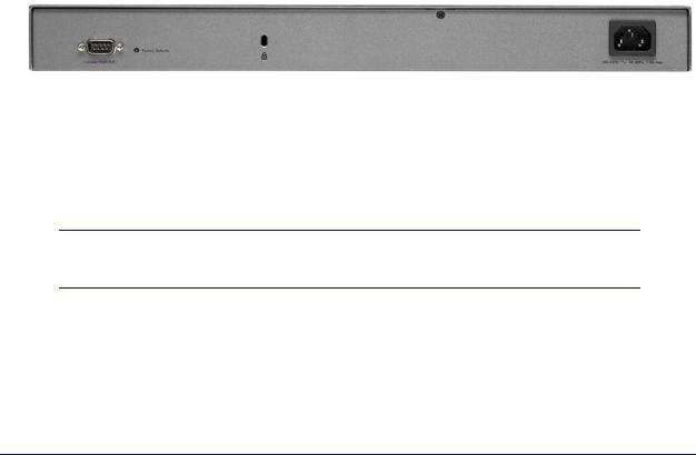
Rear Panel Features
The following figure shows the rear panel components of the wireless controller.
Figure 2.
From left to right, the wireless controller’s rear panel components are:
•Console port. RS232 port for connecting to an optional console terminal. The port has a DB9 male connector. The default baud rate is 9600 K. The configuration is 8 bits, no parity, and 1 stop bit.
Note: The console port is for debugging under guidance of NETGEAR technical support only.
•Factory Defaults button. Using a sharp object, press and hold this button for about
10 seconds until the front panel LED flashes and the wireless controller returns to factory default settings.
Introduction and Overview
13

ProSafe 20-AP Wireless Controller WC7520
Note: If you reset the wireless controller, all configuration settings are lost and the default password is restored.
•Kensington lock. Attach an optional Kensington lock to prevent unauthorized removal of the wireless controller.
•AC power socket. Attach the power cord to this socket. (There is no separate on/off power switch.)
Bottom Panel with Product Label
The product label on the bottom of the wireless controller’s enclosure displays the default IP address, default user name, and default password, as well as regulatory compliance, input power, and other information.
Figure 3.
WC7520 Wireless Controller System Components
A WC7520 wireless controller system consists of one or more wireless controllers and a collection of access points that are organized into groups based on location or network access.
The wireless controller system can include a single wireless controller, a single wireless controller with a backup wireless controller for N:1 redundancy, or a group of up to three stacked wireless controllers, with or without a redundant wireless controller.
Introduction and Overview
14

ProSafe 20-AP Wireless Controller WC7520
The WC7520 wireless controller system supports the following access point models:
•NETGEAR WNAP210 ProSafe wireless-N access point
•NETGEAR WNAP320 ProSafe wireless-N access point
•NETGEAR WNDAP350 ProSafe dual-band wireless-N access point
•NETGEAR WNDAP360 ProSafe dual-band wireless-N access point
Future releases will support additional access point models.
NETGEAR ProSafe Access Points
You can connect access points to the wireless controller either directly with an Ethernet cable through a router or switch, or remotely through an IP network. After you have used the automatic discovery process and added access points to the managed access point list on the wireless controller, the wireless controller converts the standard access points to dependent access points by pushing firmware to the access points. From then on, you can centrally manage and monitor the access points.
A WC7520 wireless controller system can support the following access points:
•WNAP210 ProSafe Wireless-N Access Point
-Supports 802.11b, 802.11g, and 802.11n network devices
-Supports Power over Ethernet (PoE) with a power consumption of up to 5.8W
-Requires minimum firmware version WNAP210_2.0.8 or a newer version.
For product documentation and firmware, see
http://support.netgear.com/app/products/model/a_id/8101.
•WNAP320 ProSafe Wireless-N Access Point
-Supports 802.11b, 802.11g, and 802.11n network devices
-Supports Power over Ethernet (PoE) with a power consumption of up to 5.8W
-Accepts optional antennas
-Requires minimum firmware version WNAP320_2.0.7 or a newer version.
For product documentation and firmware, see
http://support.netgear.com/app/products/model/a_id/18601.
•WNDAP350 ProSafe Dual Band Wireless-N Access Point
-Supports 802.11a, 802.11b, 802.11g, and 802.11n network devices
-Supports PoE with a power consumption of up to 10.75W
-Concurrent operation in 2.4 GHz and 5 GHz radio band while in 802.11n mode
-Accepts optional antennas
-Requires minimum firmware version WNDAP350_V2.0 or a newer version.
For product documentation and firmware, see
http://support.netgear.com/app/products/model/a_id/12823.
Introduction and Overview
15

ProSafe 20-AP Wireless Controller WC7520
•WNDAP360 ProSafe Dual Band Wireless-N Access Point
-Supports 802.11a, 802.11b, 802.11g, and 802.11n network devices
-Supports PoE with a power consumption of up to 10.51W
-Concurrent operation in 2.4 GHz and 5 GHz radio band while in 802.11n mode
-Accepts optional antennas
-Requires minimum firmware version WNDAP360_2.0.3 or a newer version.
For product documentation and firmware, see
http://support.netgear.com/app/products/model/a_id/19189.
What Can You Do with the WC7520 Wireless Controller?
These are some of the tasks that you can perform with a WC7520 wireless controller:
Plan a Wireless Network
•Design a WLAN. Design an efficient WLAN with building and floor dimensions for your specific environment.
•Estimate the number of required access points and their approximate locations. Estimate how many access points you need for your wireless coverage and determine their optimum location for best coverage and performance.
For more information, see Chapter 3, RF Planning.
Discover Access Points in the Network and Provision IP Addresses and Firmware
•Discover access points in the network. The access points can be in factory default state or functioning in standalone mode, but after discovery by the wireless controller and addition to the managed access point list, the access points become dependent (managed) access points.
•Provision IP addresses to the access points. Use the internal DHCP server to provision IP addresses to all or selected managed access points in the network.
•Upgrade access point firmware. Update and synchronize new firmware versions to all managed access points in the network.
For more information, see Chapter 4, Access Point Discovery and Management.
Organize the Network
•Create access point profiles. Organize access points in profiles to differentiate between SSIDs, client authentication, authentication settings, and wireless QoS settings.
•Create access point profile groups. Organize access point profiles in access point profile groups to differentiate between buildings, floors, businesses or business divisions,
Introduction and Overview
16

ProSafe 20-AP Wireless Controller WC7520
and so on. Easily assign access points to profile groups or make changes to assignments.
For more information, see Chapter 6, Managing Security Profiles and Profile Groups.
Centrally Manage the Wireless Settings for the Network
•Schedule the radios. Schedule the entire network to go offline, or schedule access point profile groups to go offline.
•Manage wireless settings and channel allocation. Manage the wireless settings such as wireless mode, data rate, channel width, and so on, for the entire network or for access point profile groups, and manage channel allocation for the entire network.
•Manage QoS settings. Manage QoS queue settings for data, background, video, and voice traffic for access point profile groups.
•Configure RF management settings. Configure WLAN healing and wireless coverage hole detection for the entire network or for access point profile groups.
For more information, see Chapter 7, Configuring Wireless and QoS Settings.
Centrally Manage Security in the Network
•Manage secure access to the network and secure data transmission. Manage client authentication, encryption, wireless client security separation, and MAC authentication in access point profiles.
•Manage authentication servers for the network. Manage all internal and external authentication servers for the entire network or for access point profile groups.
•Manage MAC authentication. Specify trusted and untrusted MAC addresses for the entire network.
•Manage rogue access points. Manage rogue access points and their associated clients in the network.
•Manage guest access. Manage guest access and captive portal access to the network.
For more information, see Chapter 8, Configuring Network Access and Security.
Manage Other Wireless Controllers in the Network
•Manage stacking. Specify the primary and secondary wireless controllers in a stack and synchronize information between the wireless controller.
•Manage redundancy groups. Specify the primary and secondary wireless controllers in redundancy group and enable failover protection.
For more information, see Chapter 10, Managing Stacking and Redundancy.
Introduction and Overview
17

ProSafe 20-AP Wireless Controller WC7520
Monitor the Network and Its Components
•View heat maps. View the real-time heat maps for a deployed WLAN. See the RF signal propagation per floor, and identify coverage holes and weak signal spots.
•Monitor the status of all wireless devices. View the status the wireless controllers, access points, clients, access point profiles, and the entire network, and view network usage statistics.
•Monitor network health. See which access points are healthy and which ones are down or compromised.
For more information, see Chapter 11, Monitoring the Wireless Network and Components.
Licenses
The wireless controller includes an built-in license to support up to 20 access points in 802.11a/b/g/n mode. You can purchase licenses in 10–access point increments (WC7510L) for support of up to 50 access points for a single wireless controller. To support 50 access points, you would need to purchase 3 WC7510L licenses; if you have three wireless controllers in a stack and want to support the maximum number of 150 access points, you would need to purchase 9 WC7510L licenses.
Adding a redundant wireless controller also requires you to purchase licenses to support the required number of access points on the redundant wireless controller.
Licenses are tied to the serial number of the wireless controller.
For more information, see the License Configuration section in the datasheet at http://support.netgear.com/app/products/model/a_id/13060.
For information about how to manage your licenses, see Manage Licenses on page 149.
Maintenance and Support
NETGEAR offers technical support seven days a week, 24 hours a day. Information about support is available on the NETGEAR ProSupport website at http://kb.netgear.com/app/answers/detail/a_id/212.
Introduction and Overview
18

ProSafe 20-AP Wireless Controller WC7520
Web Management Interface Layout
The following figure shows the menu at the top and the left of the wireless controller’s web management interface (the screen’s content has been removed for more clarity).
 Controller selection list
1st level: Main navigation menu tab |
Action buttons |
||||
2nd level: Configuration menu tab |
|||||
|
|
|
|
||
|
|
|
|
||
3rd level: Submenu link |
|
|
|
|
|
|
|
|
|
|
|
|
|
|
|
|
|
|
|
|
|
|
|
Figure 4.
A web management interface screen can include the following components:
•1st level: Main navigation menu tab. The main navigation menu tabs in the light gray bar across the top of the web management interface provide access to all configuration menu tabs of the wireless controller and remain constant. When you select a main navigation menu tab, the letters are displayed in white against a blue background.
•2nd level: Configuration menu tab. The configuration menu tabs in the blue bar (immediately below the main navigation menu bar) change according to the main navigation menu tab that you select. When you select a configuration menu tab, the letters are displayed in orange against a blue background.
•3rd level: Submenu link. Each configuration menu tab has one or more submenu links that are listed on the left side of the screen in a gray box. When you select a submenu link, the text is displayed in orange against a gray background. On many screens, the submenus are divided into a basic submenu and an advanced submenu.
•Action buttons. Action buttons change the configuration or allow you to make changes to the configuration. These are the most common action buttons:
-Apply. Saves all configuration changes made on the current screen. Saved settings are retained when the wireless controller is powered off or rebooted, while unsaved configuration changes are lost.
-Cancel. Resets options on the current screen to the last-applied or -saved settings.
-Add. Adds a new item to the current screen. Typically, a pop-up window opens that enables you to enter information in additional fields.
-Edit. Allows you to edit the configuration of the selected item.
-Remove or Delete. Removes the selected item from the table or screen configuration.
Introduction and Overview
19

ProSafe 20-AP Wireless Controller WC7520
-Back. Return to the previous screen.
-Next. Advance to the next screen.
•Controller selection list. In a stacked configuration, the controller selection list lets you select the wireless controller to configure.
Initial Connection and Configuration
Follow the steps in this section to set up the wireless controller. For additional information, see the WC7520 ProSafe Wireless Controller Installation Guide that you can access from http://kb.netgear.com/app/products/model/a_id/13060.
To set up, configure, and deploy the wireless controller:
1.Connect the wireless controller to your computer:
a.Configure a computer with a static IP address of 192.168.0.210 and 255.255.255.0 as the subnet mask.
b.Connect the wireless controller to the computer through the network or directly to one of the wireless controller’s ports.
c.Connect the power cord from the wireless controller to an AC power outlet.
d.Check the lights on the front of the wireless controller:
•Power. The green Power LED should be lit. If the Power LED is not lit, check the connections and check to see if the power outlet is controlled by a wall switch that is turned off.
•Test. The Test LED is on briefly when the controller is first turned on.
•LAN The Ethernet (LAN) LED should be lit (amber for 10/100 Mbps and green for 1000 Mbps) indicating that a connection has been made. If it is not, make sure that the Ethernet cable is securely attached at both ends.
2.Log in to the wireless controller:
a.Open your browser and type http://192.168.0.250 in the browser’s address field.
Note: You need to use a web browser such as Microsoft Internet Explorer 5.1 or later or Mozilla Firefox l.x or later with JavaScript, cookies, and SSL enabled.
Introduction and Overview
20

ProSafe 20-AP Wireless Controller WC7520
The wireless controller’s login window displays:
Figure 5.
b.When prompted, enter admin for the user name and password for the password, both in lowercase letters.
c.Click Login. The wireless controller’s web management interface displays, with the default status screen (the path is Monitor > Controller > Summary), which shows the network status and related information:
Figure 6.
Note: The Network navigation menu tab displays under the Monitor main navigation tab only when you have configured stacking.
For information about the layout and general characteristics of the web management interface, see Web Management Interface Layout on page 19.
Introduction and Overview
21

ProSafe 20-AP Wireless Controller WC7520
For information about the network status and related information, see View the Wireless Controller Summary Screen on page 180.
3.Configure the wireless controller and your network:
a.RF planning. Follow instructions in Chapter 3, RF Planning, to plan the number and location of the access points.
b.Configure your network. Follow the instructions in Chapter 4 through Chapter 10 to configure your network, including the SSIDs, security, MAC ACLs, captive portal, QoS, rate limiting, and so on.
c.Set up the wireless controller. Follow the instructions in System Planning on page 27 to select the type of deployment for your network.
d.Add the access points. Follow the steps in Access Point Discovery and Discovery Guidelines on page 51 to discover your access points and add them to wireless controller’s managed access point list.
Basic and Advanced Settings
You can deploy the wireless controller in a small wireless network with 10 or 20 access points or in a large wireless network with up to 150 access points. Small networks require a basic configuration, but large networks can become very complex and require you to configure the advanced features of the wireless controller.
Depending on your network configuration, use basic settings or advanced settings to manage your access points:
•Basic settings for a typical network. The basic settings work with most common network configurations. For example, all access points on the WLAN are for the same organization or business and therefore adhere to the same policies and use a small number of service set identifiers (SSIDs, or network names).
•Advanced settings for access point profile groups. If you have a large wireless network, or if completely separate networks share a single WLAN, use the advanced settings to set up multiple access point profile groups with multiple security profiles (SSIDs with associated security settings). For example, a shopping mall might need several access point profile groups if several businesses share a WLAN but each business has its own network. Larger networks could require multiple access point profile groups to allow different policies per building or department. The access points could have different security profiles per building and department, for example, one for guests, one for management, one for sales, and so on.
Note: Access point profile groups are also referred to as just profile groups.
Profiles, security profiles, and SSIDs (that is, SSIDs with associated security settings) are terms that are interchangeable.
Introduction and Overview
22

ProSafe 20-AP Wireless Controller WC7520
To accommodate all types of networks, almost all configuration menus of the web management interface are divided into basic and advanced submenus. The following figure shows an example of the Security > Wireless > Basic submenu on the left and the Security > Wireless > Advanced submenu on the right:
Figure 7.
Before you start the configuration of your wireless controller, decide whether you can use a basic configuration (that is, follow the basic submenus) or need to use an advanced configuration (that is, follow the advanced submenus). Once you have made your choice, configuring the wireless controller should be fairly easy if you consistently follow either the basic submenus or the advanced submenus.
Profile Groups
Each access point can support up to 8 security profiles (16 for dual-band access points), each with its own SSID, security settings, MAC ACL, rate-limiting settings, WMM, and so on.
The wireless controller follows the same architecture. A profile group on the wireless controller includes all the features that you can configure for an individual access point: up to 8 profiles (16 for dual-band access points), each of which has its own SSID, security, MAC ACL, rate-limiting settings, WMM settings, and so on.
Basic Profile
The basic profile includes all the settings that are required to configure a fully functional access point with up to 8 security profiles (16 for dual-band access points).
After you have used the automatic discovery process and added access points to the managed AP list on the wireless controller, the access points are assigned by default to the basic profile group.
If your network requires the wireless controller to manage multiple access points with different configurations, use the advanced profile.
Introduction and Overview
23

ProSafe 20-AP Wireless Controller WC7520
Advanced Profile
The advanced profile lets you configure up to 8 access point profile groups. Each group includes all the settings that are required to configure a fully functional access point with up to 8 security profiles (16 for dual-band access points).
For example, if there are four buildings, each with a completely different wireless network, you simply create four profile groups. You then assign all access points in one building to one profile group, all access points in another building to a second profile group, and so on.
For each profile group, you can create an individual radio-on/off schedule, RF management settings, MAC ACL authentication, and an authentication server. For each radio in a profile group (2.4-GHz radio and 5-GHz radio), you can create individual wireless settings, WMM, and rate-limit settings.
The following figure shows the advanced profile group architecture. The structure that is shown under Group-1 is implemented in all profile groups (that is, Group-2 through Group-8):
Group-1
 Group-2
 Group-3
 Group-4
 Group-5
 Group-6
 Group-7
 Group-8
2.4-GHz radio
5-GHz radio
|
|
|
|
|
|
|
|
|
|
|
|
|
|
|
|
|
|
|
|
|
1 |
2 |
3 |
4 |
5 |
6 |
|
7 |
|
8 |
|
1 |
2 |
3 |
4 |
5 |
6 |
7 |
8 |
||
|
|
|
|
|
|
|
|
|
|
|
|
|
|
|
|
|
|
|
|
|
|
|
Security Profiles |
|
|
|
|
|
|
|
Security Profiles |
|
|
||||||||
Figure 8.
The following figure shows an example of three access point profile groups, in which the first profile group (Group-1) has three security profiles. For each profile in this profile group, the profile name, radio mode, and authentication setting are shown. (Group-1 is the default group in the advanced profile group configuration; you need to create the other profiles groups.)
Introduction and Overview
24

ProSafe 20-AP Wireless Controller WC7520
Figure 9.
Choose a Location for the Wireless Controller
The wireless controller is suitable for use in an office environment where it can be freestanding on its runner feet or mounted into a standard 19-inch equipment rack. Alternatively, you can rack-mount the wireless controller in a wiring closet or equipment room. A mounting kit, containing two mounting brackets and screws, is provided in the wireless controller package.
Consider the following when deciding where to position the wireless controller:
•The unit is accessible and cables can be connected easily.
•Cabling is away from sources of electrical noise. These include lift shafts, microwave ovens, and air-conditioning units.
•Water or moisture cannot enter the case of the unit.
•Airflow around the unit and through the vents in the side of the case is not restricted. Provide a minimum of 25 mm or 1 inch clearance.
•The air is as free of dust as possible.
•Temperature operating limits are not likely to be exceeded. Install the unit in a clean, air-conditioned environment. For information about the recommended operating temperatures for the wireless controller, see Appendix A, Factory Default Settings and Technical Specifications.
Introduction and Overview
25

ProSafe 20-AP Wireless Controller WC7520
Deploy the Wireless Controller
To deploy the wireless controller:
1.Disconnect the wireless controller from the computer and place it where you will deploy it. If necessary, you can now reconfigure the computer that you used in the configuration process back to its original TCP/IP settings.
2.Connect an Ethernet cable from your wireless controller to a LAN port on your network.
3.Connect the power cord to the wireless controller and plug the power cord into a power outlet. The Power, Test, and Ethernet LEDs should light up. If any of these do not light up, see Troubleshoot Basic Functioning on page 194.
Introduction and Overview
26

2. System Planning and Deployment |
2 |
Scenarios |
This chapter includes the following sections:
•System Planning
•Management VLAN and Data VLAN Strategies
•Deployment Scenarios
System Planning
This section includes the following subsections:
•Preinstallation Planning
•Before You Configure a Wireless Controller
•Single Controller Configuration with Basic Profile Group
•Single Controller Configuration with Advanced Profile Groups
•Stacked Controller Configuration
Preinstallation Planning
Before you install any wireless controllers, determine the following:
•Number of access points required to provide seamless coverage
•Number of wireless controllers required
•802.11 frequency band and the channels that are optimal for Wi-Fi usage
NETGEAR recommends that you perform a site survey:
•Run a spectrum analysis of channels of the site to determine the current RF behavior and detect both 802.11 and non-802.11 noise.
•Run an access point-to-client connectivity test to determine the maximum throughput achievable on the client.
•Identify potential RF obstructions and interference sources.
•Determine areas where denser coverage might be required because of heavier usage.
27

ProSafe 20-AP Wireless Controller WC7520
After the survey is complete, use the collected data to set up an RF plan. For more information, see RF Planning Overview on page 41.
Before You Configure a Wireless Controller
These sections assume that you have deployed at least one wireless controller in your network and are ready to configure the wireless controller. For information about how to deploy the wireless controller in your network, see the WC7520 ProSafe Wireless Controller Installation Guide that you can access from http://kb.netgear.com/app/products/model/a_id/13060.
For many configurations, you can use the default wireless settings. The IP address, VLAN, DHCP server, client authentication, and data encryption settings are specific to your environment. Following are short sections that discuss these settings (with the exception of IP address settings, which are self-explanatory). For information about how to configure these settings, see the relevant sections.
VLANs
The management VLAN is the dedicated VLAN for access to the wireless controller. All traffic that is directed to the wireless controller, including HTTP, HTTPS, SNMP, and SSH traffic, is carried over the management VLAN.
If the management VLAN is also configured as a tagged VLAN (the most common configuration), the packets to and from the wireless controller carry the 802.1Q VLAN header with the assigned VLAN number. If the management VLAN is marked as untagged, the packets that are sent from the wireless controller do not carry the 802.1Q header, and all untagged packets that are sent to the wireless controller are treated as management VLAN traffic.
Note: Use a tagged VLAN or change the tagged VLAN ID only if the hubs and switches on your LAN support 802.1Q. If they do not, and you have not specifically configured a tagged VLAN with the same VLAN ID on the hubs and switches in your network, IP connectivity might be lost.
The wireless controller needs to have IP connectivity with the access points through the management VLAN. If the wireless controller and the access points are on different management VLANs, external VLAN routing needs to allow IP connectivity between the wireless controller and the access points.
For information about how to configure management VLANs, see Configure IP and VLAN Settings on page 65.
System Planning and Deployment Scenarios
28

ProSafe 20-AP Wireless Controller WC7520
Client VLANs
Each authenticated wireless user is placed into a VLAN that determines the user’s DHCP server, IP address, and Layer 2 connection. Although you could place all authenticated wireless users into the single VLAN that is specified in the basic security profile, the wireless controller allows you to group wireless users into separate VLANs based on the wireless SSID to differentiate access to network resources. For example, you might place authorized employee users into one VLAN, and itinerant users, such as contractors or guests, into a separate VLAN. To use different VLANs, you need to create different security profiles.
For information about how to configure regular VLANs, see Manage Rogue Access Points on page 113.
DHCP Server
The wireless controller can function as a DHCP server and assign IP addresses to both wireless and wired devices that are connected to it. You can add up to 64 DHCP server pools, each assigned to a different VLAN.
Client Authentication and Data Encryption
A user needs to authenticate to the WLAN to be able to access WLAN resources. The wireless controller supports several types of security methods, including those that require an external RADIUS or LDAP authentication server.
The encryption option that you can select depends upon the authentication method that you have selected. The following table lists the authentication methods available, with their corresponding encryption options:
Table 2. Authentication and encryption options
Authentication method |
Encryption option |
Authentication server |
|
|
|
Open system |
64-bit, 128-bit, or 152-bit WEP |
None |
|
|
|
Shared Key |
64-bit, 128-bit, or 152-bit WEP |
None |
|
|
|
WPA-PSK |
TKIP or TKIP+AES |
None |
|
|
|
WPA2-PSK |
AES or TKIP+AES |
None |
|
|
|
WPA-PSK and WPA2-PSK |
TKIP+AES |
None |
|
|
|
WPA |
TKIP or TKIP+AES |
One of the following authentication servers: |
|
|
• External RADIUS server |
|
|
• Internal authentication server |
|
|
• External LDAP server |
|
|
|
System Planning and Deployment Scenarios
29

ProSafe 20-AP Wireless Controller WC7520
Table 2. Authentication and encryption options (continued)
Authentication method |
Encryption option |
Authentication server |
|
|
|
WPA2 |
AES or TKIP+AES |
One of the following authentication servers: |
|
|
• External RADIUS server |
|
|
• Internal authentication server |
|
|
• External LDAP server |
|
|
|
WPA and WPA2 |
TKIP+AES |
One of the following authentication servers: |
|
|
• External RADIUS server |
|
|
• Internal authentication server |
|
|
• External LDAP server |
|
|
|
For information about how to configure client authentication and data encryption, see
Manage Rogue Access Points on page 113.
For information about how to configure authentication servers, see Manage Authentication Servers and Authentication Server Groups on page 122.
Single Controller Configuration with Basic Profile Group
A basic configuration consists of a single wireless controller that controls a collection of access points that are organized into the basic default group.
To set up a single wireless controller system with a basic profile group:
Step |
Configuration |
Web management interface path |
|
|
|
|
|
1. |
Optional: Create an RF plan. |
Plans > Layout |
|
|
|
|
|
2. |
If you have not yet done so, configure the system settings of the |
|
|
|
wireless controller: |
|
|
|
|
|
|
|
1. |
Configure the country code of operation. |
Configuration > System > General |
|
|
|
|
|
2. |
Configure the IP address of wireless controller. |
Configuration > System > IP/VLAN |
|
3. |
Verify that VLAN 1 is set as the management VLAN and is |
|
|
|
marked as untagged, which is the default setting. |
|
|
|
|
|
3. |
Configure up to 8 profiles, and for each profile, do at least the |
|
|
|
following: |
|
|
|
1. |
Configure an SSID for wireless access. |
Configuration > Profile > Basic |
|
2. |
Configure the network authentication and data encryption. |
|
|
|
|
|
|
3. |
Assign the VLAN. |
|
|
|
|
|
|
If required, configure the authentication server. |
Configuration > Security > Basic > |
|
|
|
|
Authentication Server |
4. |
Run the Discovery Wizard and add the access points to the |
Access Point > Discovery Wizard |
|
|
managed access point list. |
|
|
|
|
|
|
System Planning and Deployment Scenarios
30
 Loading...