


ProSecure Unified Threat
Management (UTM)
Appliance
Reference Manual
350 East Plumeria Drive
San Jose, CA 95134
USA
September 2011 202-10780-01 1.0
ProSecure Unified Threat Management (UTM) Appliance
© 2009–2011 NETGEAR, Inc. All rights reserved.
No part of this publication may be reproduced, transmitted, transcribed, stored in a retrieval system, or translated into any language in any form or by any means without the written permission of NETGEAR, Inc.
Technical Support
Thank you for choosing NETGEAR. To register your product, get the latest product updates, get support online, or for more information about the topics covered in this manual, visit the Support website at visit us at http://support.netgear.com.
Phone (US & Canada only): 1-888-NETGEAR
Phone (Other Countries): Check the list of phone numbers at http://support.netgear.com/app/answers/detail/a_id/984.
Product Updates
Product updates are available on the NETGEAR website at http://prosecure.netgear.com or http://kb.netgear.com/app/home.
ProSecure Forum
Go to http://prosecure.netgear.com/community/forum.php for information about the ProSecure forum and to become part of the ProSecure community.
Trademarks
NETGEAR, the NETGEAR logo, ReadyNAS, ProSafe, ProSecure, Smart Wizard, Auto Uplink, X-RAID2, and NeoTV are trademarks or registered trademarks of NETGEAR, Inc. Microsoft, Windows, Windows NT, and Vista are registered trademarks of Microsoft Corporation. Other brand and product names are registered trademarks or trademarks of their respective holders.
Statement of Conditions
To improve internal design, operational function, and/or reliability, NETGEAR reserves the right to make changes to the products described in this document without notice. NETGEAR does not assume any liability that may occur due to the use, or application of, the product(s) or circuit layout(s) described herein.
Revision History
Publication |
Version |
Publish Date |
Comments |
|
Part Number |
|
|
|
|
|
|
|
|
|
202-10780-01 |
1.0 |
September 2011 |
• Addition of the UTM9S with the following major new features: |
|
|
|
|
- xDSL module (see Chapter 1, Introduction and Chapter 3, |
|
|
|
|
Manually Configuring Internet and WAN Settings) |
|
|
|
|
- Wireless module (see Chapter 1, Introduction and |
|
|
|
|
Appendix B, Wireless Module for the UTM9S) |
|
|
|
|
- ReadyNAS integration, quarantine options, and quarantine |
|
|
|
|
logs (see Connect to a ReadyNAS and Configure |
|
|
|
|
Quarantine Settings (UTM9S Only), Query the Quarantine |
|
|
|
|
Logs (UTM9S Only), and Appendix D, ReadyNAS |
|
|
|
|
Integration |
|
|
|
|
- PPTP server (see Configure the PPTP Server (UTM9S |
|
|
|
|
Only)) |
|
|
|
|
- L2TP server (see Configure the L2TP Server (UTM9S |
|
|
|
|
Only)) |
|
|
|
|
• Update of the VPN client sections with the new VPN client (see |
|
|
|
|
Chapter 7, Virtual Private Networking Using IPSec Connections) |
|
|
|
|
|
|
|
|
|
|
|
2

ProSecure Unified Threat Management (UTM) Appliance
202-10674-02 |
1.0 |
March 2011 |
• Addition of the UTM150. |
|
|
|
• Removal of platform-specific chapters and sections because the |
|
|
|
UTM5, UTM10, and UTM25 now support the same web |
|
|
|
management interface menu layout that was already supported |
|
|
|
on the UTM50. The major changes for the UTM5, UTM10, and |
|
|
|
UTM25 are documented in Chapter 3, Manually Configuring |
|
|
|
Internet and WAN Settings, and in the following sections: |
|
|
|
- Set Web Access Exception Rules |
|
|
|
- Configure Authentication Domains, Groups, and Users |
|
|
|
• Added new features (for all UTM models). The major new |
|
|
|
features are documented in the following sections: |
|
|
|
- Electronic Licensing |
|
|
|
- VLAN Rules |
|
|
|
- Create Service Groups |
|
|
|
- Create IP Groups |
|
|
|
- Manage Digital Certificates for HTTPS Scans |
|
|
|
- Update the Firmware |
|
|
|
- View, Schedule, and Generate Reports |
|
|
|
|
202-10674-01 |
1.0 |
September 2010 |
• Addition of the UTM50 and UTM50-specific chapters and |
|
|
|
sections. |
|
|
|
• Revision of DMZ WAN and LAN DMZ default policies. |
|
|
|
|
202-10482-03 |
1.0 |
May 2010 |
• Applied numerous nontechnical edits. |
|
|
|
• Added the Requirements for Entering IP Addresses section. |
|
|
|
• Added a note about the processing of normal email traffic in the |
|
|
|
Configure Distributed Spam Analysis section. |
|
|
|
• Updated the NTP section. |
|
|
|
|
202-10482-02 |
1.0 |
January 2010 |
Updated the web management interface screens, made the |
|
|
|
manual platform-independent, added a model comparison table, |
|
|
|
and removed performance specifications (see marketing |
|
|
|
documentation for such specifications). |
|
|
|
|
202-10482-01 |
1.0 |
September 2009 |
Initial publication of this reference manual. |
|
|
|
|
3

Contents
Chapter 1 Introduction
What Is the ProSecure Unified Threat Management (UTM) Appliance? . . 13 Key Features and Capabilities . . . . . . . . . . . . . . . . . . . . . . . . . . . . . . . . . . 14
Multiple WAN Port Models for Increased Reliability or
Outbound Load Balancing . . . . . . . . . . . . . . . . . . . . . . . . . . . . . . . . . . . 15 Wireless Features. . . . . . . . . . . . . . . . . . . . . . . . . . . . . . . . . . . . . . . . . . 15 DSL Features . . . . . . . . . . . . . . . . . . . . . . . . . . . . . . . . . . . . . . . . . . . . . 15 Advanced VPN Support for Both IPSec and SSL. . . . . . . . . . . . . . . . . . 16 A Powerful, True Firewall . . . . . . . . . . . . . . . . . . . . . . . . . . . . . . . . . . . . 16 Stream Scanning for Content Filtering . . . . . . . . . . . . . . . . . . . . . . . . . . 16 Security Features . . . . . . . . . . . . . . . . . . . . . . . . . . . . . . . . . . . . . . . . . . 17 Autosensing Ethernet Connections with Auto Uplink . . . . . . . . . . . . . . . 17 Extensive Protocol Support . . . . . . . . . . . . . . . . . . . . . . . . . . . . . . . . . . 18 Easy Installation and Management . . . . . . . . . . . . . . . . . . . . . . . . . . . . 18 Maintenance and Support . . . . . . . . . . . . . . . . . . . . . . . . . . . . . . . . . . . 19 Model Comparison . . . . . . . . . . . . . . . . . . . . . . . . . . . . . . . . . . . . . . . . . 19
Service Registration Card with License Keys. . . . . . . . . . . . . . . . . . . . . . . 20 Package Contents . . . . . . . . . . . . . . . . . . . . . . . . . . . . . . . . . . . . . . . . . . . 21 Hardware Features. . . . . . . . . . . . . . . . . . . . . . . . . . . . . . . . . . . . . . . . . . . 22 Front Panel UTM5 and UTM10 . . . . . . . . . . . . . . . . . . . . . . . . . . . . . . . 22 Front Panel UTM25 . . . . . . . . . . . . . . . . . . . . . . . . . . . . . . . . . . . . . . . . 23 Front Panel UTM50 . . . . . . . . . . . . . . . . . . . . . . . . . . . . . . . . . . . . . . . . 24 Front Panel UTM150 . . . . . . . . . . . . . . . . . . . . . . . . . . . . . . . . . . . . . . . 24 Front Panel UTM9S and Modules . . . . . . . . . . . . . . . . . . . . . . . . . . . . . 25 LED Descriptions, UTM5, UTM10, UTM25, UTM50, and UTM150 . . . . 27 LED Descriptions, UTM9S and Modules . . . . . . . . . . . . . . . . . . . . . . . . 28 Rear Panel UTM5, UTM10, and UTM25 . . . . . . . . . . . . . . . . . . . . . . . . 30 Rear Panel UTM50 and UTM150 . . . . . . . . . . . . . . . . . . . . . . . . . . . . . . 31 Rear Panel UTM9S . . . . . . . . . . . . . . . . . . . . . . . . . . . . . . . . . . . . . . . . 31 Bottom Panels with Product Labels . . . . . . . . . . . . . . . . . . . . . . . . . . . . 32 Choose a Location for the UTM . . . . . . . . . . . . . . . . . . . . . . . . . . . . . . . . . 35 Use the Rack-Mounting Kit. . . . . . . . . . . . . . . . . . . . . . . . . . . . . . . . . . . 36
Chapter 2 Using the Setup Wizard to Provision the UTM in Your Network
Steps for Initial Connection. . . . . . . . . . . . . . . . . . . . . . . . . . . . . . . . . . . . . 37 Qualified Web Browsers . . . . . . . . . . . . . . . . . . . . . . . . . . . . . . . . . . . . . 38 Requirements for Entering IP Addresses . . . . . . . . . . . . . . . . . . . . . . . . 38 Log In to the UTM. . . . . . . . . . . . . . . . . . . . . . . . . . . . . . . . . . . . . . . . . . . . 38
4

ProSecure Unified Threat Management (UTM) Appliance
Web Management Interface Menu Layout . . . . . . . . . . . . . . . . . . . . . . .40 Use the Setup Wizard to Perform the Initial Configuration . . . . . . . . . . . . .42 Setup Wizard Step 1 of 10: LAN Settings. . . . . . . . . . . . . . . . . . . . . . . .43 Setup Wizard Step 2 of 10: WAN Settings . . . . . . . . . . . . . . . . . . . . . . .46 Setup Wizard Step 3 of 10: System Date and Time . . . . . . . . . . . . . . . .49 Setup Wizard Step 4 of 10: Services . . . . . . . . . . . . . . . . . . . . . . . . . . .51 Setup Wizard Step 5 of 10: Email Security. . . . . . . . . . . . . . . . . . . . . . .53 Setup Wizard Step 6 of 10: Web Security . . . . . . . . . . . . . . . . . . . . . . .55 Setup Wizard Step 7 of 10: Web Categories to Be Blocked. . . . . . . . . .57 Setup Wizard Step 8 of 10: Email Notification . . . . . . . . . . . . . . . . . . . .59 Setup Wizard Step 9 of 10: Signatures & Engine. . . . . . . . . . . . . . . . . .60 Setup Wizard Step 10 of 10: Saving the Configuration . . . . . . . . . . . . .61 Verify Correct Installation . . . . . . . . . . . . . . . . . . . . . . . . . . . . . . . . . . . . . .61 Test Connectivity . . . . . . . . . . . . . . . . . . . . . . . . . . . . . . . . . . . . . . . . . .62 Test HTTP Scanning . . . . . . . . . . . . . . . . . . . . . . . . . . . . . . . . . . . . . . .62 Register the UTM with NETGEAR . . . . . . . . . . . . . . . . . . . . . . . . . . . . . . .62 Electronic Licensing . . . . . . . . . . . . . . . . . . . . . . . . . . . . . . . . . . . . . . . .64 What to Do Next . . . . . . . . . . . . . . . . . . . . . . . . . . . . . . . . . . . . . . . . . . . . .64
Chapter 3 Manually Configuring Internet and WAN Settings
Internet and WAN Configuration Tasks . . . . . . . . . . . . . . . . . . . . . . . . . . .67 Automatically Detecting and Connecting the Internet Connections . . . . . .67 Set the UTM’s MAC Address . . . . . . . . . . . . . . . . . . . . . . . . . . . . . . . . .71 Manually Configure the Internet Connection . . . . . . . . . . . . . . . . . . . . . . .71 Configure the WAN Mode. . . . . . . . . . . . . . . . . . . . . . . . . . . . . . . . . . . . . .75 Configure Network Address Translation (All Models) . . . . . . . . . . . . . . .77 Configure Classical Routing (All Models) . . . . . . . . . . . . . . . . . . . . . . . .77
Configure Auto-Rollover Mode and the Failure Detection
Method (Multiple WAN Port Models) . . . . . . . . . . . . . . . . . . . . . . . . . . .78 Configure Load Balancing and Optional Protocol Binding . . . . . . . . . . .81 Configure Secondary WAN Addresses . . . . . . . . . . . . . . . . . . . . . . . . . . .85 Configure Dynamic DNS . . . . . . . . . . . . . . . . . . . . . . . . . . . . . . . . . . . . . .87 Configure Advanced WAN Options . . . . . . . . . . . . . . . . . . . . . . . . . . . . . .90 Additional WAN-Related Configuration Tasks . . . . . . . . . . . . . . . . . . . .92
Chapter 4 LAN Configuration
Manage Virtual LANs and DHCP Options . . . . . . . . . . . . . . . . . . . . . . . . .93 Port-Based VLANs . . . . . . . . . . . . . . . . . . . . . . . . . . . . . . . . . . . . . . . . .94 Assign and Manage VLAN Profiles. . . . . . . . . . . . . . . . . . . . . . . . . . . . .95 VLAN DHCP Options . . . . . . . . . . . . . . . . . . . . . . . . . . . . . . . . . . . . . . .96 Configure a VLAN Profile . . . . . . . . . . . . . . . . . . . . . . . . . . . . . . . . . . . .98 Configure VLAN MAC Addresses and Advanced LAN Settings. . . . . .103
Configure Multihome LAN IPs on the Default VLAN . . . . . . . . . . . . . . . .104 Manage Groups and Hosts (LAN Groups) . . . . . . . . . . . . . . . . . . . . . . . .106 Manage the Network Database . . . . . . . . . . . . . . . . . . . . . . . . . . . . . .107 Change Group Names in the Network Database . . . . . . . . . . . . . . . . .110 Set Up Address Reservation . . . . . . . . . . . . . . . . . . . . . . . . . . . . . . . .111
5

ProSecure Unified Threat Management (UTM) Appliance
Configure and Enable the DMZ Port . . . . . . . . . . . . . . . . . . . . . . . . . . . . 112
Manage Routing . . . . . . . . . . . . . . . . . . . . . . . . . . . . . . . . . . . . . . . . . . . . 115
Configure Static Routes . . . . . . . . . . . . . . . . . . . . . . . . . . . . . . . . . . . . 116
Configure Routing Information Protocol . . . . . . . . . . . . . . . . . . . . . . . . 118
Static Route Example. . . . . . . . . . . . . . . . . . . . . . . . . . . . . . . . . . . . . . 120
Chapter 5 Firewall Protection
About Firewall Protection . . . . . . . . . . . . . . . . . . . . . . . . . . . . . . . . . . . . . 121 Administrator Tips. . . . . . . . . . . . . . . . . . . . . . . . . . . . . . . . . . . . . . . . . 122 Use Rules to Block or Allow Specific Kinds of Traffic. . . . . . . . . . . . . . . . 122 Service-Based Rules . . . . . . . . . . . . . . . . . . . . . . . . . . . . . . . . . . . . . . 123 Order of Precedence for Rules. . . . . . . . . . . . . . . . . . . . . . . . . . . . . . . 130 Set LAN WAN Rules. . . . . . . . . . . . . . . . . . . . . . . . . . . . . . . . . . . . . . . 130 Set DMZ WAN Rules . . . . . . . . . . . . . . . . . . . . . . . . . . . . . . . . . . . . . . 133 Set LAN DMZ Rules . . . . . . . . . . . . . . . . . . . . . . . . . . . . . . . . . . . . . . . 136 Inbound Rule Examples . . . . . . . . . . . . . . . . . . . . . . . . . . . . . . . . . . . . 139 Outbound Rule Example . . . . . . . . . . . . . . . . . . . . . . . . . . . . . . . . . . . 143 Configure Other Firewall Features . . . . . . . . . . . . . . . . . . . . . . . . . . . . . . 144 VLAN Rules . . . . . . . . . . . . . . . . . . . . . . . . . . . . . . . . . . . . . . . . . . . . . 144 Attack Checks, VPN Pass-through, and Multicast Pass-through . . . . . 146 Set Session Limits . . . . . . . . . . . . . . . . . . . . . . . . . . . . . . . . . . . . . . . . 150 Manage the Application Level Gateway for SIP Sessions . . . . . . . . . . 151 Create Services, QoS Profiles, and Bandwidth Profiles. . . . . . . . . . . . . . 152 Add Customized Services . . . . . . . . . . . . . . . . . . . . . . . . . . . . . . . . . . 152 Create Service Groups. . . . . . . . . . . . . . . . . . . . . . . . . . . . . . . . . . . . . 154 Create IP Groups . . . . . . . . . . . . . . . . . . . . . . . . . . . . . . . . . . . . . . . . . 156 Create Quality of Service Profiles. . . . . . . . . . . . . . . . . . . . . . . . . . . . . 158 Create Bandwidth Profiles . . . . . . . . . . . . . . . . . . . . . . . . . . . . . . . . . . 160 Set a Schedule to Block or Allow Specific Traffic. . . . . . . . . . . . . . . . . . . 163 Enable Source MAC Filtering . . . . . . . . . . . . . . . . . . . . . . . . . . . . . . . . . . 164 Set Up IP/MAC Bindings . . . . . . . . . . . . . . . . . . . . . . . . . . . . . . . . . . . . . 166 Configure Port Triggering . . . . . . . . . . . . . . . . . . . . . . . . . . . . . . . . . . . . . 168 Configure Universal Plug and Play. . . . . . . . . . . . . . . . . . . . . . . . . . . . . . 171 Use the Intrusion Prevention System . . . . . . . . . . . . . . . . . . . . . . . . . . . . 172
Chapter 6 Content Filtering and Optimizing Scans
About Content Filtering and Scans. . . . . . . . . . . . . . . . . . . . . . . . . . . . . . 175
Default Email and Web Scan Settings . . . . . . . . . . . . . . . . . . . . . . . . . 176
Configure Email Protection. . . . . . . . . . . . . . . . . . . . . . . . . . . . . . . . . . . . 178
Customize Email Protocol Scan Settings . . . . . . . . . . . . . . . . . . . . . . . 178
Customize Email Antivirus and Notification Settings . . . . . . . . . . . . . . 179
Email Content Filtering . . . . . . . . . . . . . . . . . . . . . . . . . . . . . . . . . . . . . 183
Protect Against Email Spam. . . . . . . . . . . . . . . . . . . . . . . . . . . . . . . . . 186
Configure Web and Services Protection . . . . . . . . . . . . . . . . . . . . . . . . . 194
Customize Web Protocol Scan Settings and
Services (Web Applications). . . . . . . . . . . . . . . . . . . . . . . . . . . . . . . . . 194
Configure Web Malware Scans . . . . . . . . . . . . . . . . . . . . . . . . . . . . . . 197
6

ProSecure Unified Threat Management (UTM) Appliance
Configure Web Content Filtering . . . . . . . . . . . . . . . . . . . . . . . . . . . . .199 Configure Web URL Filtering . . . . . . . . . . . . . . . . . . . . . . . . . . . . . . . .206 HTTPS Scan Settings. . . . . . . . . . . . . . . . . . . . . . . . . . . . . . . . . . . . . .209 Manage Digital Certificates for HTTPS Scans . . . . . . . . . . . . . . . . . . .213 Specify Trusted Hosts. . . . . . . . . . . . . . . . . . . . . . . . . . . . . . . . . . . . . .218 Configure FTP Scans . . . . . . . . . . . . . . . . . . . . . . . . . . . . . . . . . . . . . .219
Set Web Access Exception Rules . . . . . . . . . . . . . . . . . . . . . . . . . . . . . .221 Create Custom Groups for Web Access Exceptions . . . . . . . . . . . . . .228 Create Custom Categories for Web Access Exceptions . . . . . . . . . . .231 Set Scanning Exclusions . . . . . . . . . . . . . . . . . . . . . . . . . . . . . . . . . . . . .235
Chapter 7 Virtual Private Networking
Using IPSec Connections
Considerations for Dual WAN Port Systems
(Multiple WAN Port Models Only). . . . . . . . . . . . . . . . . . . . . . . . . . . . . . .237 Use the IPSec VPN Wizard for Client and Gateway Configurations . . . .239 Create Gateway-to-Gateway VPN Tunnels with the Wizard . . . . . . . .239 Create a Client-to-Gateway VPN Tunnel . . . . . . . . . . . . . . . . . . . . . . .243 Test the Connection and View Connection and Status Information . . . . .258 Test the NETGEAR VPN Client Connection. . . . . . . . . . . . . . . . . . . . .258 NETGEAR VPN Client Status and Log Information . . . . . . . . . . . . . . .260 View the UTM IPSec VPN Connection Status . . . . . . . . . . . . . . . . . . .260 View the UTM IPSec VPN Log . . . . . . . . . . . . . . . . . . . . . . . . . . . . . . .261 Manage IPSec VPN Policies . . . . . . . . . . . . . . . . . . . . . . . . . . . . . . . . . .262 Manage IKE Policies. . . . . . . . . . . . . . . . . . . . . . . . . . . . . . . . . . . . . . .262 Manage VPN Policies. . . . . . . . . . . . . . . . . . . . . . . . . . . . . . . . . . . . . .269 Configure Extended Authentication (XAUTH) . . . . . . . . . . . . . . . . . . . . .277 Configure XAUTH for VPN Clients . . . . . . . . . . . . . . . . . . . . . . . . . . . .277 User Database Configuration . . . . . . . . . . . . . . . . . . . . . . . . . . . . . . . .278 RADIUS Client Configuration . . . . . . . . . . . . . . . . . . . . . . . . . . . . . . . .279 Assign IP Addresses to Remote Users (Mode Config). . . . . . . . . . . . . . .281 Mode Config Operation. . . . . . . . . . . . . . . . . . . . . . . . . . . . . . . . . . . . .281 Configure Mode Config Operation on the UTM . . . . . . . . . . . . . . . . . .281 Configure the ProSafe VPN Client for Mode Config Operation . . . . . .288 Test the Mode Config Connection . . . . . . . . . . . . . . . . . . . . . . . . . . . .295 Modify or Delete a Mode Config Record. . . . . . . . . . . . . . . . . . . . . . . .296 Configure Keep-Alives and Dead Peer Detection . . . . . . . . . . . . . . . . . .297 Configure Keep-Alives . . . . . . . . . . . . . . . . . . . . . . . . . . . . . . . . . . . . .297 Configure Dead Peer Detection . . . . . . . . . . . . . . . . . . . . . . . . . . . . . .298 Configure NetBIOS Bridging with IPSec VPN . . . . . . . . . . . . . . . . . . . . .299 Configure the PPTP Server (UTM9S Only) . . . . . . . . . . . . . . . . . . . . . . .300 View the Active PPTP Users . . . . . . . . . . . . . . . . . . . . . . . . . . . . . . . .302 Configure the L2TP Server (UTM9S Only). . . . . . . . . . . . . . . . . . . . . . . .303 View the Active L2TP Users . . . . . . . . . . . . . . . . . . . . . . . . . . . . . . . . .304
7

ProSecure Unified Threat Management (UTM) Appliance
Chapter 8 Virtual Private Networking
Using SSL Connections
SSL VPN Portal Options . . . . . . . . . . . . . . . . . . . . . . . . . . . . . . . . . . . . . 306 Use the SSL VPN Wizard for Client Configurations . . . . . . . . . . . . . . . . . 307 SSL VPN Wizard Step 1 of 6 (Portal Settings) . . . . . . . . . . . . . . . . . . . 308 SSL VPN Wizard Step 2 of 6 (Domain Settings) . . . . . . . . . . . . . . . . . 310 SSL VPN Wizard Step 3 of 6 (User Settings). . . . . . . . . . . . . . . . . . . . 314 SSL VPN Wizard Step 4 of 6 (Client Addresses and Routes) . . . . . . . 316 SSL VPN Wizard Step 5 of 6 (Port Forwarding). . . . . . . . . . . . . . . . . . 317 SSL VPN Wizard Step 6 of 6 (Verify and Save Your Settings) . . . . . . 319 Access the New SSL Portal Login Screen . . . . . . . . . . . . . . . . . . . . . . 320 View the UTM SSL VPN Connection Status . . . . . . . . . . . . . . . . . . . . 322 View the UTM SSL VPN Log . . . . . . . . . . . . . . . . . . . . . . . . . . . . . . . . 322 Manually Configure and Edit SSL Connections . . . . . . . . . . . . . . . . . . . . 323 Create the Portal Layout. . . . . . . . . . . . . . . . . . . . . . . . . . . . . . . . . . . . 324 Configure Domains, Groups, and Users. . . . . . . . . . . . . . . . . . . . . . . . 328 Configure Applications for Port Forwarding . . . . . . . . . . . . . . . . . . . . . 328 Configure the SSL VPN Client . . . . . . . . . . . . . . . . . . . . . . . . . . . . . . . 331 Use Network Resource Objects to Simplify Policies . . . . . . . . . . . . . . 334 Configure User, Group, and Global Policies. . . . . . . . . . . . . . . . . . . . . 336
Chapter 9 Managing Users, Authentication, and VPN Certificates
Authentication Process and Options . . . . . . . . . . . . . . . . . . . . . . . . . . . . 343 Configure Authentication Domains, Groups, and Users. . . . . . . . . . . . . . 345 Login Portals. . . . . . . . . . . . . . . . . . . . . . . . . . . . . . . . . . . . . . . . . . . . . 345 Active Directories and LDAP Configurations . . . . . . . . . . . . . . . . . . . . 349 Configure Domains. . . . . . . . . . . . . . . . . . . . . . . . . . . . . . . . . . . . . . . . 353 Configure Groups . . . . . . . . . . . . . . . . . . . . . . . . . . . . . . . . . . . . . . . . . 359 Configure User Accounts . . . . . . . . . . . . . . . . . . . . . . . . . . . . . . . . . . . 362 Set User Login Policies . . . . . . . . . . . . . . . . . . . . . . . . . . . . . . . . . . . . 365 Change Passwords and Other User Settings. . . . . . . . . . . . . . . . . . . . 369 DC Agent . . . . . . . . . . . . . . . . . . . . . . . . . . . . . . . . . . . . . . . . . . . . . . . 370 Configure RADIUS VLANs . . . . . . . . . . . . . . . . . . . . . . . . . . . . . . . . . . 376 Configure Global User Settings . . . . . . . . . . . . . . . . . . . . . . . . . . . . . . 377 View and Log Out Active Users . . . . . . . . . . . . . . . . . . . . . . . . . . . . . . 378 Manage Digital Certificates for VPN Connections . . . . . . . . . . . . . . . . . . 381 VPN Certificates Screen. . . . . . . . . . . . . . . . . . . . . . . . . . . . . . . . . . . . 382 Manage CA Certificates . . . . . . . . . . . . . . . . . . . . . . . . . . . . . . . . . . . . 382 Manage Self-Signed Certificates . . . . . . . . . . . . . . . . . . . . . . . . . . . . . 384 Manage the Certificate Revocation List . . . . . . . . . . . . . . . . . . . . . . . . 388
Chapter 10 Network and System Management
Performance Management. . . . . . . . . . . . . . . . . . . . . . . . . . . . . . . . . . . . 389
Bandwidth Capacity . . . . . . . . . . . . . . . . . . . . . . . . . . . . . . . . . . . . . . . 389
Features That Reduce Traffic. . . . . . . . . . . . . . . . . . . . . . . . . . . . . . . . 390
Features That Increase Traffic . . . . . . . . . . . . . . . . . . . . . . . . . . . . . . . 393
8

ProSecure Unified Threat Management (UTM) Appliance
Use QoS and Bandwidth Assignments to Shift the Traffic Mix . . . . . . .396 Monitoring Tools for Traffic Management. . . . . . . . . . . . . . . . . . . . . . .396 System Management . . . . . . . . . . . . . . . . . . . . . . . . . . . . . . . . . . . . . . . .397 Change Passwords and Administrator and Guest Settings . . . . . . . . .397 Configure Remote Management Access . . . . . . . . . . . . . . . . . . . . . . .399 Use a Simple Network Management Protocol Manager. . . . . . . . . . . .401 Manage the Configuration File . . . . . . . . . . . . . . . . . . . . . . . . . . . . . . .403 Update the Firmware . . . . . . . . . . . . . . . . . . . . . . . . . . . . . . . . . . . . . .405 Update the Scan Signatures and Scan Engine Firmware . . . . . . . . . .410 Configure Date and Time Service. . . . . . . . . . . . . . . . . . . . . . . . . . . . .412
Connect to a ReadyNAS and Configure Quarantine
Settings (UTM9S Only). . . . . . . . . . . . . . . . . . . . . . . . . . . . . . . . . . . . . . .414 Log Storage . . . . . . . . . . . . . . . . . . . . . . . . . . . . . . . . . . . . . . . . . . . . .414 Connect to a ReadyNAS. . . . . . . . . . . . . . . . . . . . . . . . . . . . . . . . . . . .415 Configure the Quarantine Settings . . . . . . . . . . . . . . . . . . . . . . . . . . . .416
Chapter 11 Monitoring System Access and Performance
Enable the WAN Traffic Meter . . . . . . . . . . . . . . . . . . . . . . . . . . . . . . . . .419 Configure Logging, Alerts, and Event Notifications . . . . . . . . . . . . . . . . .422 Configure the Email Notification Server . . . . . . . . . . . . . . . . . . . . . . . .422 Configure and Activate System, Email, and Syslog Logs. . . . . . . . . . .423 How to Send Syslogs over a VPN Tunnel between Sites. . . . . . . . . . .427 Configure and Activate Update Failure and Attack Alerts. . . . . . . . . . .429 Configure and Activate Firewall Logs . . . . . . . . . . . . . . . . . . . . . . . . . .432 Monitor Real-Time Traffic, Security, and Statistics. . . . . . . . . . . . . . . . . .433 View Status Screens . . . . . . . . . . . . . . . . . . . . . . . . . . . . . . . . . . . . . . . .439 View the System Status . . . . . . . . . . . . . . . . . . . . . . . . . . . . . . . . . . . .439 View the Active VPN Users . . . . . . . . . . . . . . . . . . . . . . . . . . . . . . . . .451 View the VPN Tunnel Connection Status . . . . . . . . . . . . . . . . . . . . . . .452 View the PPTP and L2TP Server Status (UTM9S Only) . . . . . . . . . . .453 View the Port Triggering Status . . . . . . . . . . . . . . . . . . . . . . . . . . . . . .454 View the WAN Ports Status . . . . . . . . . . . . . . . . . . . . . . . . . . . . . . . . .456 View Attached Devices and the DHCP Log . . . . . . . . . . . . . . . . . . . . .457 Query the Logs . . . . . . . . . . . . . . . . . . . . . . . . . . . . . . . . . . . . . . . . . . . . .460 Query and Download Logs . . . . . . . . . . . . . . . . . . . . . . . . . . . . . . . . . .461 Example: Use the Logs to Identify Infected Clients . . . . . . . . . . . . . . .466 Log Management . . . . . . . . . . . . . . . . . . . . . . . . . . . . . . . . . . . . . . . . .466 Query the Quarantine Logs (UTM9S Only) . . . . . . . . . . . . . . . . . . . . . . .467 Query the Quarantined Logs . . . . . . . . . . . . . . . . . . . . . . . . . . . . . . . .467 View and Manage the Quarantined Spam Table . . . . . . . . . . . . . . . . .470 View and Manage the Quarantined Infected Files Table . . . . . . . . . . .471 Spam Reports for End Users . . . . . . . . . . . . . . . . . . . . . . . . . . . . . . . .472 View, Schedule, and Generate Reports . . . . . . . . . . . . . . . . . . . . . . . . . .473 Report Filtering Options . . . . . . . . . . . . . . . . . . . . . . . . . . . . . . . . . . . .474 Use Report Templates and View Reports Onscreen . . . . . . . . . . . . . .476 Schedule, Email, and Manage Reports . . . . . . . . . . . . . . . . . . . . . . . .480 Use Diagnostics Utilities . . . . . . . . . . . . . . . . . . . . . . . . . . . . . . . . . . . . . .482
Use the Network Diagnostic Tools
9

ProSecure Unified Threat Management (UTM) Appliance
(All UTM Models Except the UTM9S). . . . . . . . . . . . . . . . . . . . . . . . . . 483 Use the Network Diagnostic Tools (UTM9S) . . . . . . . . . . . . . . . . . . . . 484 Use the Real-Time Traffic Diagnostics Tool
(All UTM Models Except the UTM9S). . . . . . . . . . . . . . . . . . . . . . . . . . 486 Use the Real-Time Traffic Diagnostics Tool (UTM9S) . . . . . . . . . . . . . 487 Gather Important Log Information and Generate a
Network Statistics Report (All Models) . . . . . . . . . . . . . . . . . . . . . . . . . 488
Chapter 12 Troubleshooting and Using Online Support
Basic Functioning . . . . . . . . . . . . . . . . . . . . . . . . . . . . . . . . . . . . . . . . . . . 492 Power LED Not On . . . . . . . . . . . . . . . . . . . . . . . . . . . . . . . . . . . . . . . . 492 Test LED Never Turns Off . . . . . . . . . . . . . . . . . . . . . . . . . . . . . . . . . . 492 LAN or WAN Port LEDs Not On . . . . . . . . . . . . . . . . . . . . . . . . . . . . . . 493 Troubleshoot the Web Management Interface . . . . . . . . . . . . . . . . . . . . . 493 When You Enter a URL or IP Address, a Time-Out Error Occurs . . . . . . 494 Troubleshoot the ISP Connection . . . . . . . . . . . . . . . . . . . . . . . . . . . . . . 494 Troubleshoot a TCP/IP Network Using a Ping Utility . . . . . . . . . . . . . . . . 496 Test the LAN Path to Your UTM. . . . . . . . . . . . . . . . . . . . . . . . . . . . . . 496 Test the Path from Your PC to a Remote Device. . . . . . . . . . . . . . . . . 497 Restore the Default Configuration and Password . . . . . . . . . . . . . . . . . . 498 Problems with Date and Time . . . . . . . . . . . . . . . . . . . . . . . . . . . . . . . . . 499 Use Online Support . . . . . . . . . . . . . . . . . . . . . . . . . . . . . . . . . . . . . . . . . 499 Enable Remote Troubleshooting . . . . . . . . . . . . . . . . . . . . . . . . . . . . . 499 Send Suspicious Files to NETGEAR for Analysis . . . . . . . . . . . . . . . . 500 Access the Knowledge Base and Documentation . . . . . . . . . . . . . . . . 501
Appendix A xDSL Module for the UTM9S
xDSL Module Configuration Tasks. . . . . . . . . . . . . . . . . . . . . . . . . . . . . . 502
Configure the xDSL Settings . . . . . . . . . . . . . . . . . . . . . . . . . . . . . . . . . . 503
Automatically Detecting and Connecting the Internet Connection . . . . . . 505
Set the UTM’s MAC Address . . . . . . . . . . . . . . . . . . . . . . . . . . . . . . . . 508
Manually Configure the Internet Connection . . . . . . . . . . . . . . . . . . . . . . 508
Configure the WAN Mode . . . . . . . . . . . . . . . . . . . . . . . . . . . . . . . . . . . . 512
Configure Network Address Translation. . . . . . . . . . . . . . . . . . . . . . . . 513
Configure Classical Routing . . . . . . . . . . . . . . . . . . . . . . . . . . . . . . . . . 514
Configure Auto-Rollover Mode and the Failure Detection Method . . . . 514
Configure Load Balancing and Optional Protocol Binding . . . . . . . . . . 517
Configure Secondary WAN Addresses . . . . . . . . . . . . . . . . . . . . . . . . . . 521
Configure Dynamic DNS . . . . . . . . . . . . . . . . . . . . . . . . . . . . . . . . . . . . . 523
Configure Advanced WAN Options . . . . . . . . . . . . . . . . . . . . . . . . . . . . . 526
Additional WAN-Related Configuration Tasks . . . . . . . . . . . . . . . . . . . 528
Appendix B Wireless Module for the UTM9S
Overview of the Wireless Module. . . . . . . . . . . . . . . . . . . . . . . . . . . . . . . 529
Configuration Order . . . . . . . . . . . . . . . . . . . . . . . . . . . . . . . . . . . . . . . 530
Wireless Equipment Placement and Range Guidelines . . . . . . . . . . . . 530
10
ProSecure Unified Threat Management (UTM) Appliance
Configure the Basic Radio Settings . . . . . . . . . . . . . . . . . . . . . . . . . . . . .531 Operating Frequency (Channel) Guidelines . . . . . . . . . . . . . . . . . . . . .534 Wireless Data Security Options . . . . . . . . . . . . . . . . . . . . . . . . . . . . . . . .534 Wireless Security Profile. . . . . . . . . . . . . . . . . . . . . . . . . . . . . . . . . . . . . .536 Before You Change the SSID, WEP, and WPA Settings . . . . . . . . . . .537 Configure and Enable Wireless Security Profiles . . . . . . . . . . . . . . . . .538 Configure the Access Point . . . . . . . . . . . . . . . . . . . . . . . . . . . . . . . . . . .542 Restrict Wireless Access by MAC Address . . . . . . . . . . . . . . . . . . . . .545 View the Access Point Status and Connected Clients . . . . . . . . . . . . .546 Configure a Wireless Distribution System . . . . . . . . . . . . . . . . . . . . . . . .548 Configure Advanced Radio Settings. . . . . . . . . . . . . . . . . . . . . . . . . . . . .549 Configure Advanced Profile and WMM QoS Priority Settings . . . . . . . . .551 Advanced Profile Settings. . . . . . . . . . . . . . . . . . . . . . . . . . . . . . . . . . .551 WMM QoS Priority Settings . . . . . . . . . . . . . . . . . . . . . . . . . . . . . . . . .553 Test Basic Wireless Connectivity . . . . . . . . . . . . . . . . . . . . . . . . . . . . . . .554
Appendix C Network Planning for Dual WAN Ports (Multiple WAN Port Models Only)
What to Consider Before You Begin. . . . . . . . . . . . . . . . . . . . . . . . . . . . .556 Cabling and Computer Hardware Requirements . . . . . . . . . . . . . . . . .557 Computer Network Configuration Requirements . . . . . . . . . . . . . . . . .558 Internet Configuration Requirements . . . . . . . . . . . . . . . . . . . . . . . . . .558 Overview of the Planning Process . . . . . . . . . . . . . . . . . . . . . . . . . . . . . .560 Inbound Traffic . . . . . . . . . . . . . . . . . . . . . . . . . . . . . . . . . . . . . . . . . . . . .561 Inbound Traffic to a Single WAN Port System . . . . . . . . . . . . . . . . . . .562 Inbound Traffic to a Dual WAN Port System . . . . . . . . . . . . . . . . . . . .562 Virtual Private Networks . . . . . . . . . . . . . . . . . . . . . . . . . . . . . . . . . . . . . .563 VPN Road Warrior (Client-to-Gateway) . . . . . . . . . . . . . . . . . . . . . . . .564 VPN Gateway-to-Gateway . . . . . . . . . . . . . . . . . . . . . . . . . . . . . . . . . .567 VPN Telecommuter (Client-to-Gateway through a NAT Router) . . . . .569
Appendix D ReadyNAS Integration
Supported ReadyNAS Models . . . . . . . . . . . . . . . . . . . . . . . . . . . . . . . . .572 Install the UTM9S Add-On on the ReadyNAS . . . . . . . . . . . . . . . . . . . . .573 Connect to the ReadyNAS on the UTM9S . . . . . . . . . . . . . . . . . . . . . . . .575
Appendix E Two-Factor Authentication
Why Do I Need Two-Factor Authentication? . . . . . . . . . . . . . . . . . . . . . .578 What Are the Benefits of Two-Factor Authentication? . . . . . . . . . . . . .578 What Is Two-Factor Authentication?. . . . . . . . . . . . . . . . . . . . . . . . . . .579 NETGEAR Two-Factor Authentication Solutions . . . . . . . . . . . . . . . . . . .579
Appendix F System Logs and Error Messages
System Log Messages . . . . . . . . . . . . . . . . . . . . . . . . . . . . . . . . . . . . . . .583
System Startup . . . . . . . . . . . . . . . . . . . . . . . . . . . . . . . . . . . . . . . . . . .583
11

ProSecure Unified Threat Management (UTM) Appliance
Reboot . . . . . . . . . . . . . . . . . . . . . . . . . . . . . . . . . . . . . . . . . . . . . . . . . 583
Service Logs. . . . . . . . . . . . . . . . . . . . . . . . . . . . . . . . . . . . . . . . . . . . . 583
NTP . . . . . . . . . . . . . . . . . . . . . . . . . . . . . . . . . . . . . . . . . . . . . . . . . . . 584
Login/Logout. . . . . . . . . . . . . . . . . . . . . . . . . . . . . . . . . . . . . . . . . . . . . 584
Firewall Restart. . . . . . . . . . . . . . . . . . . . . . . . . . . . . . . . . . . . . . . . . . . 585
IPSec Restart . . . . . . . . . . . . . . . . . . . . . . . . . . . . . . . . . . . . . . . . . . . . 585
WAN Status . . . . . . . . . . . . . . . . . . . . . . . . . . . . . . . . . . . . . . . . . . . . . 585
Traffic Metering Logs . . . . . . . . . . . . . . . . . . . . . . . . . . . . . . . . . . . . . . 589
Unicast, Multicast, and Broadcast Logs . . . . . . . . . . . . . . . . . . . . . . . . 589
Invalid Packet Logging . . . . . . . . . . . . . . . . . . . . . . . . . . . . . . . . . . . . . 590
Content-Filtering and Security Logs . . . . . . . . . . . . . . . . . . . . . . . . . . . . . 592
Web Filtering and Content-Filtering Logs. . . . . . . . . . . . . . . . . . . . . . . 592
Spam Logs . . . . . . . . . . . . . . . . . . . . . . . . . . . . . . . . . . . . . . . . . . . . . . 594
Traffic Logs. . . . . . . . . . . . . . . . . . . . . . . . . . . . . . . . . . . . . . . . . . . . . . 595
Virus Logs. . . . . . . . . . . . . . . . . . . . . . . . . . . . . . . . . . . . . . . . . . . . . . . 595
Email Filter Logs. . . . . . . . . . . . . . . . . . . . . . . . . . . . . . . . . . . . . . . . . . 595
IPS Logs. . . . . . . . . . . . . . . . . . . . . . . . . . . . . . . . . . . . . . . . . . . . . . . . 596
Port Scan Logs. . . . . . . . . . . . . . . . . . . . . . . . . . . . . . . . . . . . . . . . . . . 596
Application Logs . . . . . . . . . . . . . . . . . . . . . . . . . . . . . . . . . . . . . . . . . . 596
Routing Logs . . . . . . . . . . . . . . . . . . . . . . . . . . . . . . . . . . . . . . . . . . . . . . 597
LAN-to-WAN Logs . . . . . . . . . . . . . . . . . . . . . . . . . . . . . . . . . . . . . . . . 597
LAN-to-DMZ Logs. . . . . . . . . . . . . . . . . . . . . . . . . . . . . . . . . . . . . . . . . 597
DMZ-to-WAN Logs . . . . . . . . . . . . . . . . . . . . . . . . . . . . . . . . . . . . . . . . 597
WAN-to-LAN Logs . . . . . . . . . . . . . . . . . . . . . . . . . . . . . . . . . . . . . . . . 598
DMZ-to-LAN Logs. . . . . . . . . . . . . . . . . . . . . . . . . . . . . . . . . . . . . . . . . 598
WAN-to-DMZ Logs . . . . . . . . . . . . . . . . . . . . . . . . . . . . . . . . . . . . . . . . 598
Appendix G Default Settings and Technical Specifications
Default Settings . . . . . . . . . . . . . . . . . . . . . . . . . . . . . . . . . . . . . . . . . . . . 599
Physical and Technical Specifications . . . . . . . . . . . . . . . . . . . . . . . . . . . 601
Appendix H Notification of Compliance (Wired)
Appendix I Notification of Compliance (Wireless)
Index
12

1. Introduction |
1 |
|
|
||
|
|
|
This chapter provides an overview of the features and capabilities of the NETGEAR ProSecure™ Unified Threat Management (UTM) Appliance. This chapter contains the following sections:
•What Is the ProSecure Unified Threat Management (UTM) Appliance?
•Key Features and Capabilities
•Service Registration Card with License Keys
•Package Contents
•Hardware Features
•Choose a Location for the UTM
Note: For more information about the topics covered in this manual, visit the NETGEAR support website at http://support.netgear.com.
What Is the ProSecure Unified Threat Management (UTM)
Appliance?
The ProSecure Unified Threat Management (UTM) Appliance, hereafter referred to as the UTM, connects your local area network (LAN) to the Internet through one or two external broadband access devices such as cable modems, DSL modems, satellite dishes, or wireless ISP radio antennas, or a combination of those. Dual wide area network (WAN) ports allow you to increase the effective data rate to the Internet by utilizing both WAN ports to carry session traffic, or to maintain a backup connection in case of failure of your primary Internet connection.
As a complete security solution, the UTM combines a powerful, flexible firewall with a content scan engine that uses NETGEAR Stream Scanning technology to protect your network from denial of service (DoS) attacks, unwanted traffic, traffic with objectionable content, spam, phishing, and web-borne threats such as spyware, viruses, and other malware threats.
13

ProSecure Unified Threat Management (UTM) Appliance
The UTM provides advanced IPSec and SSL VPN technologies for secure and simple remote connections. The use of Gigabit Ethernet LAN and WAN ports ensures extremely high data transfer speeds.
The UTM is a plug-and-play device that can be installed and configured within minutes.
Key Features and Capabilities
The UTM provides the following key features and capabilities:
•For the single WAN port models, a single 10/100/1000 Mbps Gigabit Ethernet WAN port. For the multiple WAN port models, dual or quad 10/100/1000 Mbps Gigabit Ethernet WAN ports for load balancing or failover protection of your Internet connection, providing increased system reliability or increased data rate.
•Built-in fouror six-port 10/100/1000 Mbps Gigabit Ethernet LAN switch for extremely fast data transfer between local network resources.
•Wireless module (UTM9S only) for either 2.4-GHz or 5-GHz wireless modes.
•xDLS module (UTM9S only) for ADSL and VDSL.
•Advanced IPSec VPN and SSL VPN support.
•Depending on the model, bundled with a one-user license of the NETGEAR ProSafe VPN Client software (VPN01L).
•Advanced Stateful Packet Inspection (SPI) firewall with multi-NAT support.
•Patent-pending Stream Scanning technology that enables scanning of real-time protocols such as HTTP.
•Comprehensive web and email security, covering six major network protocols: HTTP, HTTPS, FTP, SMTP, POP3, and IMAP.
•Malware database containing hundreds of thousands of signatures of spyware, viruses, and other malware threats.
•Very frequently updated malware signatures, hourly if required. The UTM can automatically check for new malware signatures as frequently as every 15 minutes.
•Multiple antispam technologies to provide extensive protection against unwanted mail.
•Easy, web-based wizard setup for installation and management.
•SNMP manageable.
•Front panel LEDs for easy monitoring of status and activity.
•Flash memory for firmware upgrade.
•Internal universal switching power supply.
Introduction
14

ProSecure Unified Threat Management (UTM) Appliance
Multiple WAN Port Models for Increased Reliability or Outbound Load Balancing
The UTM product line offers models with two broadband WAN ports. The second WAN port allows you to connect a second broadband Internet line that can be configured on a mutually exclusive basis to:
•Provide backup and rollover if one line is inoperable, ensuring that you are never disconnected.
•Load balance, or use both Internet lines simultaneously for outgoing traffic. A UTM with dual WAN ports balances users between the two lines for maximum bandwidth efficiency.
See Appendix C, Network Planning for Dual WAN Ports (Multiple WAN Port Models Only) for the planning factors to consider when implementing the following capabilities with dual WAN port gateways:
•Single or multiple exposed hosts
•Virtual private networks
Wireless Features
Wireless client connections are supported on the UTM9S with a UTM9SWLSN wireless module installed. The UTM9S supports the following wireless features:
•2.4-GHz radio and 5-GHz radio. Either 2.4-GHz band support with 802.11b/g/n/ wireless modes or 5-GHz band support with 802.11a/n wireless modes.
•WMM QoS priority. Wi-Fi Multimedia (WMM) Quality of Service (QoS) priority settings to map one of four queues to each Differentiated Services Code Point (DSCP) value.
•Wireless Distribution System (WDS). WDS enables expansion of a wireless network through two or more access points that are interconnected.
•Access control. The Media Access Control (MAC) address filtering feature can ensure that only trusted wireless stations can use the UTM to gain access to your LAN.
•Hidden mode. The SSID is not broadcast, assuring that only clients configured with the correct SSID can connect.
•Secure and economical operation. Adjustable power output allows more secure or economical operation.
DSL Features
DSL is supported on the UTM9S with a UTM9SDSL xDSL module installed. The UTM9S automatically detects the following types of DSL connections:
•ADSL, ADSL2, and ADLS2+
•VDSL and VDSL2
Annex A, Annex B, and Annex M are supported to accommodate PPPoE, PPPoA, and IPoA ISP connections.
Introduction
15

ProSecure Unified Threat Management (UTM) Appliance
Advanced VPN Support for Both IPSec and SSL
The UTM supports IPSec and SSL virtual private network (VPN) connections.
•IPSec VPN delivers full network access between a central office and branch offices, or between a central office and telecommuters. Remote access by telecommuters requires the installation of VPN client software on the remote computer.
-IPSec VPN with broad protocol support for secure connection to other IPSec gateways and clients.
-Depending on the model, bundled with a one-user license of the NETGEAR ProSafe VPN Client software (VPN01L).
•SSL VPN provides remote access for mobile users to selected corporate resources without requiring a preinstalled VPN client on their computers.
-Uses the familiar Secure Sockets Layer (SSL) protocol, commonly used for e-commerce transactions, to provide client-free access with customizable user portals and support for a wide variety of user repositories.
-Allows browser-based, platform-independent remote access through a number of popular browsers, such as Microsoft Internet Explorer, Mozilla Firefox, and Apple Safari.
-Provides granular access to corporate resources based on user type or group membership.
A Powerful, True Firewall
Unlike simple NAT routers, the UTM is a true firewall, using Stateful Packet Inspection (SPI) to defend against hacker attacks. Its firewall features have the following capabilities:
•DoS protection. Automatically detects and thwarts denial of service (DoS) attacks such as Ping of Death and SYN flood.
•Secure firewall. Blocks unwanted traffic from the Internet to your LAN.
•Schedule policies. Permits scheduling of firewall policies by day and time.
•Logs security incidents. Logs security events such as blocked incoming traffic, port scans, attacks, and administrator logins. You can configure the firewall to email the log to you at specified intervals. You can also configure the firewall to send immediate alert messages to your email address or email pager whenever a significant event occurs.
Stream Scanning for Content Filtering
Stream Scanning is based on the simple observation that network traffic travels in streams. The UTM scan engine starts receiving and analyzing traffic as the stream enters the network. As soon as a number of bytes are available, scanning starts. The scan engine continues to scan more bytes as they become available, while at the same time another thread starts to deliver the bytes that have been scanned.
Introduction
16

ProSecure Unified Threat Management (UTM) Appliance
This multithreaded approach, in which the receiving, scanning, and delivering processes occur concurrently, ensures that network performance remains unimpeded. The result is that file scanning is up to five times faster than with traditional antivirus solutions—a performance advantage that you will notice.
Stream Scanning also enables organizations to withstand massive spikes in traffic, as in the event of a malware outbreak. The scan engine has the following capabilities:
•Real-time protection. The patent-pending Stream Scanning technology enables scanning of previously undefended real-time protocols, such as HTTP. Network activities susceptible to latency (for example, web browsing) are no longer brought to a standstill.
•Comprehensive protection. Provides both web and email security, covering six major network protocols: HTTP, HTTPS, FTP, SMTP, POP3, and IMAP. The UTM uses enterprise-class scan engines employing both signature-based and distributed spam analysis to stop both known and unknown threats. The malware database contains hundreds of thousands of signatures of spyware, viruses, and other malware.
•Objectionable traffic protection. The UTM prevents objectionable content from reaching your computers. You can control access to the Internet content by screening for web services, web addresses, and keywords within web addresses. You can log and report attempts to access objectionable Internet sites.
•Automatic signature updates. Malware signatures are updated as frequently as every hour, and the UTM can check automatically for new signatures as frequently as every 15 minutes.
Security Features
The UTM is equipped with several features designed to maintain security:
•PCs hidden by NAT. NAT opens a temporary path to the Internet for requests originating from the local network. Requests originating from outside the LAN are discarded, preventing users outside the LAN from finding and directly accessing the computers on the LAN.
•Port forwarding with NAT. Although NAT prevents Internet locations from directly accessing the PCs on the LAN, the UTM allows you to direct incoming traffic to specific PCs based on the service port number of the incoming request. You can specify forwarding of single ports or ranges of ports.
•DMZ port. Incoming traffic from the Internet is usually discarded by the UTM unless the traffic is a response to one of your local computers or a service for which you have configured an inbound rule. Instead of discarding this traffic, you can use the dedicated demilitarized zone (DMZ) port to forward the traffic to one PC on your network.
Autosensing Ethernet Connections with Auto Uplink
With its internal fouror six-port 10/100/1000 Mbps switch and single or dual (model-dependant) 10/100/1000 WAN ports, the UTM can connect to either a 10 Mbps standard Ethernet network, a 100 Mbps Fast Ethernet network, or a 1000 Mbps Gigabit
Introduction
17

ProSecure Unified Threat Management (UTM) Appliance
Ethernet network. The four LAN and one or two WAN interfaces are autosensing and capable of full-duplex or half-duplex operation.
The UTM incorporates Auto UplinkTM technology. Each Ethernet port automatically senses whether the Ethernet cable plugged into the port should have a normal connection such as to a PC or an uplink connection such as to a switch or hub. That port then configures itself correctly. This feature eliminates the need for you to think about crossover cables, as Auto Uplink accommodates either type of cable to make the right connection.
Extensive Protocol Support
The UTM supports the Transmission Control Protocol/Internet Protocol (TCP/IP) and Routing Information Protocol (RIP). For further information about TCP/IP, see Internet Configuration Requirements on page 558. The UTM provides the following protocol support:
•IP address sharing by NAT. The UTM allows many networked PCs to share an Internet account using only a single IP address, which might be statically or dynamically assigned by your Internet service provider (ISP). This technique, known as Network Address Translation (NAT), allows the use of an inexpensive single-user ISP account.
•Automatic configuration of attached PCs by DHCP. The UTM dynamically assigns network configuration information, including IP, gateway, and Domain Name Server (DNS) addresses, to attached PCs on the LAN using the Dynamic Host Configuration Protocol (DHCP). This feature greatly simplifies configuration of PCs on your local network.
•DNS proxy. When DHCP is enabled and no DNS addresses are specified, the firewall provides its own address as a DNS server to the attached PCs. The firewall obtains actual DNS addresses from the ISP during connection setup and forwards DNS requests from the LAN.
•PPP over Ethernet (PPPoE). PPPoE is a protocol for connecting remote hosts to the Internet over a DSL connection by simulating a dial-up connection.
•Quality of Service (QoS). The UTM supports QoS, including traffic prioritization and traffic classification with Type of Service (ToS) and Differentiated Services Code Point (DSCP) marking.
Easy Installation and Management
You can install, configure, and operate the UTM within minutes after connecting it to the network. The following features simplify installation and management tasks:
•Browser-based management. Browser-based configuration allows you to easily configure the UTM from almost any type of operating system, such as Windows, Macintosh, or Linux. A user-friendly Setup Wizard is provided, and online help documentation is built into the browser-based web management interface.
•Autodetection of ISP. The UTM automatically senses the type of Internet connection, asking you only for the information required for your type of ISP account.
Introduction
18

ProSecure Unified Threat Management (UTM) Appliance
•IPSec VPN Wizard. The UTM includes the NETGEAR IPSec VPN Wizard so you can easily configure IPSec VPN tunnels according to the recommendations of the Virtual Private Network Consortium (VPNC). This ensures that the IPSec VPN tunnels are interoperable with other VPNC-compliant VPN routers and clients.
•SSL VPN Wizard. The UTM includes the NETGEAR SSL VPN Wizard so you can easily configure SSL connections over VPN according to the recommendations of the VPNC. This ensures that the SSL connections are interoperable with other VPNC-compliant VPN routers and clients.
•SNMP. The UTM supports the Simple Network Management Protocol (SNMP) to let you monitor and manage log resources from an SNMP-compliant system manager. The SNMP system configuration lets you change the system variables for MIB2.
•Diagnostic functions. The UTM incorporates built-in diagnostic functions such as ping, traceroute, DNS lookup, and remote reboot.
•Remote management. The UTM allows you to log in to the web management interface from a remote location on the Internet. For security, you can limit remote management access to a specified remote IP address or range of addresses.
•Visual monitoring. The UTM’s front panel LEDs provide an easy way to monitor its status and activity.
Maintenance and Support
NETGEAR offers the following features to help you maximize your use of the UTM:
•Flash memory for firmware upgrades.
•Technical support seven days a week, 24 hours a day. Information about support is available on the NETGEAR ProSecure website at http://prosecure.netgear.com/support/index.php.
Model Comparison
The following table compares the UTM models to show the differences. For performance specifications and sizing guidelines, see NETGEAR’s marketing documentation at http://prosecure.netgear.com.
Table 1. Differences between the UTM models
Feature |
UTM5 |
UTM9S |
UTM10 |
UTM25 |
UTM50 |
UTM150 |
|
|
|
|
|
|
|
IPSec VPN tunnels |
|
|
|
|
|
|
|
|
|
|
|
|
|
Number of supported site-to-site |
5 |
10 |
10 |
25 |
50 |
150 |
IPSec VPN tunnels (from which the |
|
|
|
|
|
|
model derives its model number, |
|
|
|
|
|
|
with the exception of the UTM9S) |
|
|
|
|
|
|
|
|
|
|
|
|
|
Hardware |
|
|
|
|
|
|
LAN ports (Gigabit RJ-45) |
4 |
4 |
4 |
4 |
6 |
4 |
|
|
|
|
|
|
|
Introduction
19

ProSecure Unified Threat Management (UTM) Appliance
Table 1. Differences between the UTM models (continued)
Feature |
UTM5 |
UTM9S |
UTM10 |
UTM25 |
UTM50 |
UTM150 |
|
|
|
|
|
|
|
WAN ports (Gigabit RJ-45) |
1 |
2 |
1 |
2 |
2 |
4 |
|
|
|
|
|
|
|
DMZ interfaces (configurable) |
1 |
1 |
1 |
1 |
1 |
1 |
|
|
|
|
|
|
|
USB ports |
1 |
1 |
1 |
1 |
1 |
1 |
|
|
|
|
|
|
|
Console ports (RS232) |
1 |
1 |
1 |
1 |
1 |
1 |
|
|
|
|
|
|
|
Flash memory |
2 GB |
2 GB |
2 GB |
2 GB |
2 GB |
2 GB |
RAM |
512 MB |
512 MB |
512 MB |
1 GB |
1 GB |
1 GB |
|
|
|
|
|
|
|
Modules |
|
|
|
|
|
|
|
|
|
|
|
|
|
xDSL module with RJ11 port |
No |
Yes |
No |
No |
No |
No |
|
|
|
|
|
|
|
Wireless module |
No |
Yes |
No |
No |
No |
No |
|
|
|
|
|
|
|
Deployment |
|
|
|
|
|
|
|
|
|
|
|
|
|
VLAN support |
Yes |
Yes |
Yes |
Yes |
Yes |
Yes |
|
|
|
|
|
|
|
Dual WAN auto-rollover mode |
No |
Yes |
No |
Yes |
Yes |
Yes |
|
|
|
|
|
|
|
Dual WAN load balancing mode |
No |
Yes |
No |
Yes |
Yes |
Yes |
|
|
|
|
|
|
|
Single WAN mode |
Yes |
Yes |
Yes |
Yes |
Yes |
Yes |
|
|
|
|
|
|
|
Service Registration Card with License Keys
Be sure to store the license key card that came with your UTM (see a sample card in the following figure) in a secure location. If you do not use electronic licensing (see Electronic Licensing on page 64), you need these service license keys to activate your product during the initial setup.
Introduction
20
ProSecure Unified Threat Management (UTM) Appliance
Figure 1.
Note: When you reset the UTM to the original factory default settings after you have entered the license keys to activate the UTM (see Register the UTM with NETGEAR on page 62), the license keys are erased. The license keys and the different types of licenses that are available for the UTM are no longer displayed on the Registration screen. However, after you have reconfigured the UTM to connect to the Internet and to the NETGEAR registration server, the UTM retrieves and restores all registration information based on its MAC address and hardware serial number. You do not need to reenter the license keys and reactivate the UTM.
Package Contents
The UTM product package contains the following items:
•ProSecure Unified Threat Management (UTM) Appliance
•One AC power cable
•Rubber feet (4)
•One rack-mounting kit (depends on UTM model)
•ProSecure Unified Threat Management UTM Installation Guide
Introduction
21

ProSecure Unified Threat Management (UTM) Appliance
•Resource CD, including:
-Application Notes and other helpful information
-ProSafe VPN Client software (VPN01L) (depends on the UTM model)
•Service Registration Card with license key(s)
If any of the parts are incorrect, missing, or damaged, contact your NETGEAR dealer. Keep the carton, including the original packing materials, in case you need to return the product for repair.
Hardware Features
The front panel ports and LEDs, rear panel ports, and bottom labels of the UTM models are described in the following sections:
•Front Panel UTM5 and UTM10
•Front Panel UTM25
•Front Panel UTM50
•Front Panel UTM150
•Front Panel UTM9S and Modules
•LED Descriptions, UTM5, UTM10, UTM25, UTM50, and UTM150
•LED Descriptions, UTM9S and Modules
•Rear Panel UTM5, UTM10, and UTM25
•Rear Panel UTM50 and UTM150
•Rear Panel UTM9S
•Bottom Panels with Product Labels
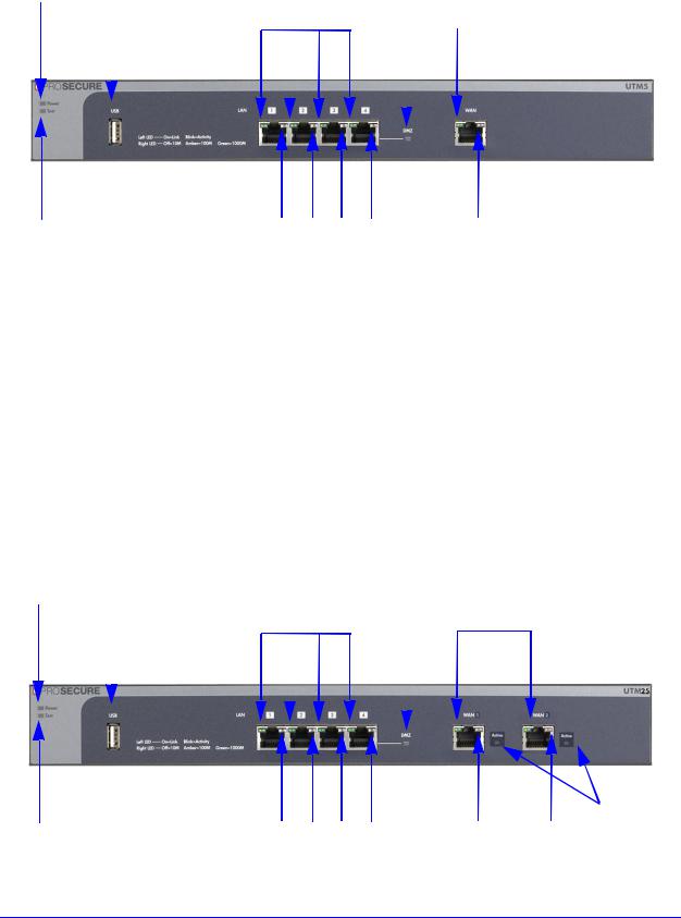
Front Panel UTM5 and UTM10
Viewed from left to right, the UTM5 and UTM10 front panel contains the following ports:
•One nonfunctioning USB port. This port is included for future management enhancements. The port is currently not operable on the UTM.
•LAN Ethernet ports. Four switched N-way automatic speed negotiating, Auto MDI/MDIX, Gigabit Ethernet ports with RJ-45 connectors.
•WAN Ethernet port. One independent N-way automatic speed negotiating, Auto MDI/MDIX, Gigabit Ethernet ports with RJ-45 connectors.
The front panel also contains three groups of status indicator light-emitting diodes (LEDs), including Power and Test LEDs, LAN LEDs, and WAN LEDs, all of which are explained in detail in Table 2 on page 27. In addition, the front panel provides some LED explanation to the left of the LAN ports.
Introduction
22
ProSecure Unified Threat Management (UTM) Appliance
Power LED |
|
|
|
|
|
|
|
|
|
|
|
|
|
DMZ LED |
|||||||||
|
|
USB port |
Left LAN LEDs |
|
|
|
Left WAN LED |
||||||||||||||||
|
|
|
|
|
|
|
|
|
|
|
|
|
|
|
|
|
|
|
|
|
|
|
|
|
|
|
|
|
|
|
|
|
|
|
|
|
|
|
|
|
|
|
|
|
|
|
|
|
|
|
|
|
|
|
|
|
|
|
|
|
|
|
|
|
|
|
|
|
|
|
|
|
|
|
|
|
|
|
|
|
|
|
|
|
|
|
|
|
|
|
|
|
|
|
|
|
|
|
|
|
|
|
|
|
|
|
|
|
|
|
|
|
|
|
|
|
|
|
|
|
|
|
|
|
|
|
|
|
|
|
|
|
|
|
|
|
|
|
|
|
|
|
|
Test LED |
|
|
|
Right WAN LED |
Right LAN LEDs |
||||
Figure 2. Front panel UTM5 and UTM10
Front Panel UTM25
Viewed from left to right, the UTM25 front panel contains the following ports:
•One nonfunctioning USB port. This port is included for future management enhancements. The port is currently not operable on the UTM.
•LAN Ethernet ports. Four switched N-way automatic speed negotiating, Auto MDI/MDIX, Gigabit Ethernet ports with RJ-45 connectors.
•WAN Ethernet ports. Two independent N-way automatic speed negotiating, Auto MDI/MDIX, Gigabit Ethernet ports with RJ-45 connectors.
The front panel also contains three groups of status indicator LEDs, including Power and Test LEDs, LAN LEDs, and WAN LEDs, all of which are explained in detail in the Table 2 on page 27. In addition, the front panel provides some LED explanation to the left of the LAN ports.
Power LED |
|
|
|
|
|
|
|
|
|
|
|
|
|
DMZ LED |
||||||||||||
|
|
USB port |
Left LAN LEDs |
|
|
|
Left WAN LEDs |
|||||||||||||||||||
|
|
|
|
|
|
|
|
|
|
|
|
|
|
|
|
|
|
|
|
|
|
|
|
|
|
|
|
|
|
|
|
|
|
|
|
|
|
|
|
|
|
|
|
|
|
|
|
|
|
|
|
|
|
|
|
|
|
|
|
|
|
|
|
|
|
|
|
|
|
|
|
|
|
|
|
|
|
|
|
|
|
|
|
|
|
|
|
|
|
|
|
|
|
|
|
|
|
|
|
|
|
|
|
|
|
|
|
|
|
|
|
|
|
|
|
|
|
|
|
|
|
|
|
|
|
|
|
|
|
|
|
|
|
|
|
|
|
|
|
|
|
|
|
|
|
|
|
|
|
|
|
|
|
|
|
|
|
|
|
|
|
|
|
|
|
|
|
|
|
|
|
|
|
|
|
|
|
|
|
|
|
|
|
|
|
|
|
|
|
|
|
|
|
|
Active |
|
|
|
|
|
|
WAN |
Test LED |
Right LAN LEDs |
Right WAN LEDs LEDs |
||||
Figure 3. Front panel UTM25 |
|
|
|
|
|
|
Introduction
23
ProSecure Unified Threat Management (UTM) Appliance
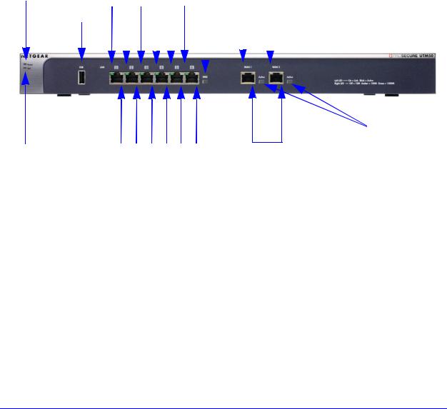
Front Panel UTM50
Viewed from left to right, the UTM front panel contains the following ports (see the following figure, which shows a multiple WAN port model, the UTM25):
•One nonfunctioning USB port. This port is included for future management enhancements. The port is currently not operable on the UTM.
•LAN Ethernet ports. Six switched N-way automatic speed negotiating, Auto MDI/MDIX, Gigabit Ethernet ports with RJ-45 connectors.
•WAN Ethernet ports. Two independent N-way automatic speed negotiating, Auto MDI/MDIX, Gigabit Ethernet ports with RJ-45 connectors.
The front panel also contains three groups of status indicator LEDs, including Power and Test LEDs, LAN LEDs, and WAN LEDs, all of which are explained in detail in Table 2 on page 27. In addition, the front panel provides some LED explanation to the right of the WAN ports.
Power LED |
|
Left LAN LEDs |
|
|
|
|
|
Left WAN LEDs |
||||||||||||||||||||||||||
|
|
|
|
USB port |
|
|
|
|
|
|
|
|
|
|
|
|
|
|
|
|
|
DMZ LED |
|
|
|
|
|
|
|
|||||
|
|
|
|
|
|
|
|
|
|
|
|
|
|
|
|
|
|
|
|
|
||||||||||||||
|
|
|
|
|
|
|
|
|
|
|
|
|
|
|
|
|
|
|
|
|
|
|
|
|
|
|
|
|
|
|
|
|
|
|
|
|
|
|
|
|
|
|
|
|
|
|
|
|
|
|
|
|
|
|
|
|
|
|
|
|
|
|
|
|
|
|
|
|
|
|
|
|
|
|
|
|
|
|
|
|
|
|
|
|
|
|
|
|
|
|
|
|
|
|
|
|
|
|
|
|
|
|
|
|
|
|
|
|
|
|
|
|
|
|
|
|
|
|
|
|
|
|
|
|
|
|
|
|
|
|
|
|
|
|
|
|
|
|
|
|
|
|
|
|
|
|
|
|
|
|
|
|
|
|
|
|
|
|
|
|
|
|
|
|
|
|
|
|
|
|
|
|
|
|
|
|
|
|
|
|
|
|
|
|
|
|
|
|
|
|
|
|
|
|
|
|
|
|
|
|
|
|
|
|
|
|
|
|
|
Active
WAN
LEDs
|
|
|
|
Right WAN LEDs |
Test LED |
Right LAN LEDs |
|||
Figure 4. Front panel UTM50
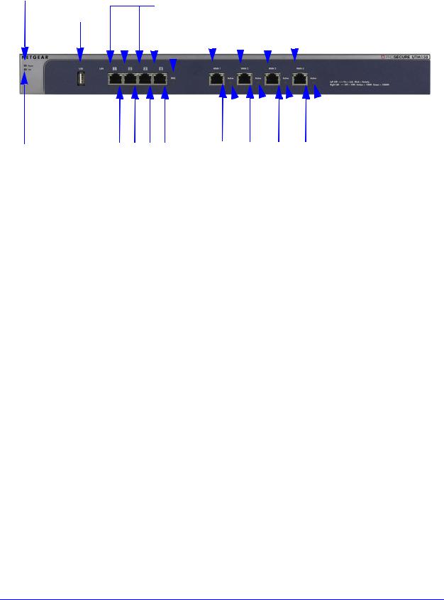
Front Panel UTM150
Viewed from left to right, the UTM150 front panel contains the following ports:
•One nonfunctioning USB port. This port is included for future management enhancements. The port is currently not operable on the UTM.
•LAN Ethernet ports. Four switched N-way automatic speed negotiating, Auto MDI/MDIX, Gigabit Ethernet ports with RJ-45 connectors.
•WAN Ethernet ports. Four independent N-way automatic speed negotiating, Auto MDI/MDIX, Gigabit Ethernet ports with RJ-45 connectors.
The front panel also contains three groups of status indicator LEDs, including Power and Test LEDs, LAN LEDs, and WAN LEDs, all of which are explained in detail inTable 2 on page 27. In addition, the front panel provides some LED explanation to the right of the WAN ports.
Introduction
24
ProSecure Unified Threat Management (UTM) Appliance
Power LED |
Left LAN LEDs |
Left WAN LEDs |
|||||||||||||||||||||
|
|
|
|
USB port |
|
|
|
|
|
|
|
DMZ LED |
|
|
|
|
|
|
|||||
|
|
|
|
|
|
|
|
|
|
|
|
|
|
|
|
|
|
|
|
|
|
|
|
|
|
|
|
|
|
|
|
|
|
|
|
|
|
|
|
|
|
|
|
|
|
|
|
|
|
|
|
|
|
|
|
|
|
|
|
|
|
|
|
|
|
|
|
|
|
|
|


 Active WAN LEDs
|
|
|
|
|
|
Test LED |
Right LAN LEDs |
Right WAN LEDs |
|||
Figure 5. Front panel UTM150
Front Panel UTM9S and Modules
Viewed from left to right, the UTM9S front panel contains the following ports and slots:
•One nonfunctioning USB port. This port is included for future management enhancements. The port is currently not operable on the UTM9S.
•LAN Ethernet ports. Four switched N-way automatic speed negotiating, Auto MDI/MDIX, Gigabit Ethernet ports with RJ-45 connectors.
•WAN Ethernet ports. Two independent N-way automatic speed negotiating, Auto MDI/MDIX, Gigabit Ethernet ports with RJ-45 connectors.
The front panel also contains three groups of status indicator LEDs, including Power and Test LEDs, LAN LEDs, and WAN LEDs, all of which are explained in detail in Table 3 on page 28. Some LED explanation is provided on the front panel below the LAN and WAN ports.
Introduction
25

ProSecure Unified Threat Management (UTM) Appliance
Left WAN LEDs |
Slot 1 |
Slot 2 |
Power LED
Left LAN
USB port
DMZ
|
|
|
|
|
|
|
|
Active WAN LEDs |
|
|
|
|
|
|
|
|
|
|
|
|
|
|
||||
|
|
Test LED Right LAN |
||||||
USB LED |
Right WAN LEDs |
|||||||
Figure 6. Front panel UTM9S
UTM9SDSL xDSL Module
The following xDSL modules are available for insertion in one of the UTM9S slots:
•UTM9SDSLA. VDSL/ADSL2+ module, Annex A.
•UTM9SDSLB. VDSL/ADSL2+ module, Annex B.
The xDLS module provides one RJ-11 port for connection to a telephone line. The two LEDs are explained in Table 3 on page 28.
Figure 7. UTM9SDSL xDSL module
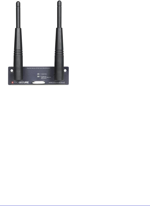
UTM9SWLSN Wireless Module
The wireless module (UTM9SWLSN) can be inserted in one of the UTM9S slots. The wireless module does not provide any ports. The antennas are detachable. The two LEDs are explained in Table 3 on page 28.
Introduction
26
ProSecure Unified Threat Management (UTM) Appliance
Figure 8. UTM9SWLSN wireless module
LED Descriptions, UTM5, UTM10, UTM25, UTM50, and
UTM150
The following table describes the function of each LED.
Table 2. LED descriptions UTM5, UTM10, UTM25, UTM50, and UTM150
LED |
Activity |
Description |
|
|
|
Power LED |
On (green) |
Power is supplied to the UTM. |
|
|
|
|
Off |
Power is not supplied to the UTM. |
|
|
|
Test LED |
On (amber) during |
Test mode. The UTM is initializing. After approximately 2 minutes, when the |
|
startup |
UTM has completed its initialization, the Test LED goes off. |
|
|
|
|
On (amber) during |
The initialization has failed, or a hardware failure has occurred. |
|
any other time |
|
|
|
|
|
Blinking (amber) |
The UTM is writing to flash memory (during upgrading or resetting to |
|
|
defaults). |
|
|
|
|
Off |
The UTM has booted successfully. |
|
|
|
Introduction
27

ProSecure Unified Threat Management (UTM) Appliance
Table 2. LED descriptions UTM5, UTM10, UTM25, UTM50, and UTM150 (continued)
LED |
Activity |
Description |
|
|
|
|
|
LAN ports |
|
|
|
|
|
|
|
Left LED |
Off |
The LAN port has no link. |
|
|
|
|
|
|
On (green) |
The LAN port has detected a link with a connected Ethernet device. |
|
|
|
|
|
|
Blinking (green) |
Data is being transmitted or received by the LAN port. |
|
|
|
|
|
Right LED |
Off |
The LAN port is operating at 10 Mbps. |
|
|
|
|
|
|
On (amber) |
The LAN port is operating at 100 Mbps. |
|
|
|
|
|
|
On (green) |
The LAN port is operating at 1000 Mbps. |
|
|
|
|
|
DMZ LED |
Off |
Port 4 (UTM5, UTM9S, UTM10, UTM25, and UTM150) or port 6 (UTM50) is |
|
|
|
operating as a normal LAN port. |
|
|
|
|
|
|
On (green) |
Port 4 (UTM5, UTM9S, UTM10, UTM25, and UTM150) or port 6 (UTM50) is |
|
|
|
operating as a dedicated hardware DMZ port. |
|
|
|
|
|
WAN ports |
|
|
|
|
|
|
|
Left LED |
Off |
The WAN port has no physical link, that is, no Ethernet cable is plugged into |
|
|
|
the UTM. |
|
|
|
|
|
|
On (green) |
The WAN port has a valid connection with a device that provides an Internet |
|
|
|
connection. |
|
|
|
|
|
|
Blinking (green) |
Data is being transmitted or received by the WAN port. |
|
|
|
|
|
Right LED |
Off |
The WAN port is operating at 10 Mbps. |
|
|
|
|
|
|
On (amber) |
The WAN port is operating at 100 Mbps. |
|
|
|
|
|
|
On (green) |
The WAN port is operating at 1000 Mbps. |
|
|
|
|
|
Active LED |
Off |
The WAN port either is not enabled or has no link to the Internet. |
|
(multiple |
|
|
|
On (green) |
The WAN port has a valid Internet connection. |
||
WAN port |
|||
models only) |
|
|
|
|
|
|
LED Descriptions, UTM9S and Modules
The following table describes the function of each LED on the UTM9S and the modules.
Table 3. LED descriptions UTM9S
LED |
Activity |
Description |
|
|
|
Power LED |
On (green) |
Power is supplied to the UTM. |
|
|
|
|
Off |
Power is not supplied to the UTM. |
|
|
|
Introduction
28

ProSecure Unified Threat Management (UTM) Appliance
Table 3. LED descriptions UTM9S (continued)
LED |
Activity |
Description |
|
|
|
|
|
Test LED |
On (amber) during |
Test mode. The UTM is initializing. After approximately 2 minutes, when the |
|
|
startup |
UTM has completed its initialization, the Test LED goes off. |
|
|
On (amber) during |
The initialization has failed, or a hardware failure has occurred. |
|
|
any other time |
|
|
|
|
|
|
|
Blinking (amber) |
The UTM is writing to flash memory (during upgrading or resetting to |
|
|
|
defaults). |
|
|
|
|
|
|
Off |
The UTM has booted successfully. |
|
|
|
|
|
USB LED |
Nonfunctioning |
The USB port is currently not operable on the UTM9S. |
|
|
|
|
|
LAN ports |
|
|
|
|
|
|
|
Left LED |
Off |
The LAN port has no link. |
|
|
|
|
|
|
On (green) |
The LAN port has detected a link with a connected Ethernet device. |
|
|
|
|
|
|
Blinking (green) |
Data is being transmitted or received by the LAN port. |
|
|
|
|
|
Right LED |
Off |
The LAN port is operating at 10 Mbps. |
|
|
|
|
|
|
On (amber) |
The LAN port is operating at 100 Mbps. |
|
|
|
|
|
|
On (green) |
The LAN port is operating at 1000 Mbps. |
|
|
|
|
|
DMZ LED |
Off |
Port 4 is operating as a normal LAN port. |
|
|
|
|
|
|
On (green) |
Port 4 is operating as a dedicated hardware DMZ port. |
|
|
|
|
|
WAN ports |
|
|
|
|
|
|
|
Left LED |
Off |
The WAN port has no physical link, that is, no Ethernet cable is plugged into |
|
|
|
the UTM. |
|
|
On (green) |
The WAN port has a valid connection with a device that provides an Internet |
|
|
|
connection. |
|
|
|
|
|
|
Blinking (green) |
Data is being transmitted or received by the WAN port. |
|
|
|
|
|
Right LED |
Off |
The WAN port is operating at 10 Mbps. |
|
|
|
|
|
|
On (amber) |
The WAN port is operating at 100 Mbps. |
|
|
|
|
|
|
On (green) |
The WAN port is operating at 1000 Mbps. |
|
|
|
|
|
Active LED |
Off |
The WAN port either is not enabled or has no link to the Internet. |
|
|
|
|
|
|
On (green) |
The WAN port has a valid Internet connection. |
|
|
|
|
|
Wireless module |
|
||
Module |
Off |
The module is not enabled. |
|
Status LED |
|
|
|
On (green) |
The module is enabled. |
||
|
|||
|
|
|
|
Introduction
29
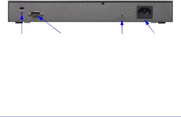
ProSecure Unified Threat Management (UTM) Appliance
Table 3. LED descriptions UTM9S (continued)
LED |
Activity |
Description |
|
|
|
|
|
|
|
|
|
Wireless |
Off |
The wireless access point is not enabled. |
|
Link LED |
|
|
|
On (green) |
The wireless access point is enabled in 2.4-GHz operating mode. |
||
|
|||
|
|
|
|
|
Blinking (green) |
There is wireless activity in 2.4-GHz operating mode. |
|
|
|
|
|
|
On (yellow) |
The wireless access point is enabled in 5-GHz operating mode. |
|
|
|
|
|
|
Blinking (yellow) |
There is wireless activity in 5-GHz operating mode. |
|
|
|
|
|
xDSL module |
|
||
|
|
|
|
Module |
Off |
The module is enabled or has a link the the telephone line. |
|
Status LED |
|
|
|
On (green) |
The module either is not enabled or has no link to the telephone line. |
||
|
|||
|
|
|
|
Link LED |
Off |
The xDLS port has no Internet connection. |
|
|
|
|
|
|
On (green) |
The xDSL port functions in ADSL mode. |
|
|
|
|
|
|
On (yellow) |
The xDSL port functions in VDSL mode. |
|
|
|
|
|
Rear Panel UTM5, UTM10, and UTM25
The rear panel of the UTM includes a cable lock receptacle, a console port, a factory default Reset button, and an AC power connection.
|
|
|
|
Factory Defaults AC power |
|
Security lock |
Console port |
||||
receptacle |
|
reset button |
receptacle |
||
Figure 9. Rear panel of the UTM5, UTM10, and UTM25
Viewed from left to right, the rear panel of the UTM5, UTM10, and UTM25 contains the following components:
1.Cable security lock receptacle.
2.Console port. Port for connecting to an optional console terminal. The port has a DB9 male connector. The default baud rate is 9600 K. The pinouts are (2) Tx, (3) Rx, (5) and (7) Gnd.
3.Factory default Reset button. Using a sharp object, press and hold this button for about
8 seconds until the front panel Test LED flashes to reset the UTM to factory default settings. Configuration changes are lost, and the default password is restored.
4.AC power receptacle. Universal AC input (100–240 VAC, 50–60 Hz).
Introduction
30
 Loading...