


 Loading...
ProSAFE Wireless Controller
Models WC7500, WC7600,
WC7600v2, and WC9500
User Manual
October 2016 202-11659-02
350 East Plumeria Drive
San Jose, CA 95134
USA

ProSAFE Wireless Controller
Support
Thank you for purchasing this NETGEAR product. You can visit www.netgear.com/support to register your product, get help, access the latest downloads and user manuals, and join our community. We recommend that you use only official NETGEAR support resources.
Conformity
For the current EU Declaration of Conformity, visit http://kb.netgear.com/app/answers/detail/a_id/11621.
Compliance
For regulatory compliance information, visit http://www.netgear.com/about/regulatory.
See the regulatory compliance document before connecting the power supply.
Trademarks
© NETGEAR, Inc., NETGEAR and the NETGEAR Logo are trademarks of NETGEAR, Inc. Any non-NETGEAR trademarks are used for reference purposes only.
Revision History
Publication Part |
Publish Date |
Comments |
Number |
|
|
|
|
|
202-11659-02 |
October 2016 |
• Added the following new features: |
|
|
- Support for model WAC740 (see Supported NETGEAR Access Points). |
|
|
- Link aggregation for WAC740 access point (see Change Access Point |
|
|
Information on the Managed AP List and Enable Link Aggregation on a |
|
|
WAC740 Access Point). |
|
|
- MU-MIMO for the WAC740 access point (see Configure WiFi Settings |
|
|
for the Basic Profile Group and Configure WiFi Settings for an |
|
|
Advanced Profile Group). |
|
|
- Enhanced syslog support for all wireless controller models (see |
|
|
Configure the Syslog Settings for an Internal Syslog Location). |
|
|
- AirQual for the WAC740 access point (see Manage AirQual for a Profile |
|
|
Group and View AirQual for the Channels in a Profile Group). |
|
|
- Diagnostic option to send logs for controller-managed access points |
|
|
over the network (see View the Console Debug Logs of an Access |
|
|
Point). |
|
|
- Diagnostic option to capture packets for controller-managed access |
|
|
points (see Capture WiFi Packets). |
|
|
• Added Appendix A, Controller-Managed Access Points, which describes |
|
|
the limited web management interface for controller-managed access |
|
|
points. |
|
|
|
202-11659-01 |
April 2016 |
• First publication of the combined manual for all models. |
|
|
• Introduction of model WC7500 and model WC7600v2. |
|
|
|
2

Contents
Chapter 1 Introduction
Models, Key Features, and Capabilities . . . . . . . . . . . . . . . . . . . . . . . . . . . . . . . . . 12
Model WC7500 . . . . . . . . . . . . . . . . . . . . . . . . . . . . . . . . . . . . . . . . . . . . . . . . . . 12
Model WC7600 . . . . . . . . . . . . . . . . . . . . . . . . . . . . . . . . . . . . . . . . . . . . . . . . . . 12
Model WC7600v2 . . . . . . . . . . . . . . . . . . . . . . . . . . . . . . . . . . . . . . . . . . . . . . . . 13
Model WC9500 . . . . . . . . . . . . . . . . . . . . . . . . . . . . . . . . . . . . . . . . . . . . . . . . . . 13
Model Scalability and Feature Differences . . . . . . . . . . . . . . . . . . . . . . . . . . . . 13
Model Common Features and Capabilities . . . . . . . . . . . . . . . . . . . . . . . . . . . . 14
What Can You Do With a Wireless Controller? . . . . . . . . . . . . . . . . . . . . . . . . . . . 15
Licenses. . . . . . . . . . . . . . . . . . . . . . . . . . . . . . . . . . . . . . . . . . . . . . . . . . . . . . . . . . . . 17
Maintenance and Support . . . . . . . . . . . . . . . . . . . . . . . . . . . . . . . . . . . . . . . . . . . . 17
Chapter 2 Hardware Descriptions
Package Contents . . . . . . . . . . . . . . . . . . . . . . . . . . . . . . . . . . . . . . . . . . . . . . . . . . . 19
Hardware Models WC7500 and WC7600v2 . . . . . . . . . . . . . . . . . . . . . . . . . . . . 19
WC7500 and WC7600v2 Front Panel Ports and Slots . . . . . . . . . . . . . . . . . 19
WC7500 and WC7600v2 Back Panel Components . . . . . . . . . . . . . . . . . . . . 21
WC7500 and WC7600v2 Product Labels . . . . . . . . . . . . . . . . . . . . . . . . . . . . 21
Hardware Models WC7600 and WC9500 . . . . . . . . . . . . . . . . . . . . . . . . . . . . . . 22
WC7600 and WC9500 Front Panel Ports and Slots . . . . . . . . . . . . . . . . . . . . 22
WC7600 and WC9500 Back Panel Components . . . . . . . . . . . . . . . . . . . . . . 23
WC7600 and WC9500 Product Labels . . . . . . . . . . . . . . . . . . . . . . . . . . . . . . 24
LED Functions (All Models) . . . . . . . . . . . . . . . . . . . . . . . . . . . . . . . . . . . . . . . . . . . 25
Wireless Controller System Components . . . . . . . . . . . . . . . . . . . . . . . . . . . . . . . 26
Supported NETGEAR Access Points . . . . . . . . . . . . . . . . . . . . . . . . . . . . . . . . . . . . 27
Supported NETGEAR Antennas . . . . . . . . . . . . . . . . . . . . . . . . . . . . . . . . . . . . . . . . 30
Chapter 3 System Planning and Deployment Scenarios
Basic and Advanced Setting Concepts . . . . . . . . . . . . . . . . . . . . . . . . . . . . . . . . . . 33
Profile Group Concepts . . . . . . . . . . . . . . . . . . . . . . . . . . . . . . . . . . . . . . . . . . . . . . 34
Basic Profile . . . . . . . . . . . . . . . . . . . . . . . . . . . . . . . . . . . . . . . . . . . . . . . . . . . . . . 34
Advanced Profile. . . . . . . . . . . . . . . . . . . . . . . . . . . . . . . . . . . . . . . . . . . . . . . . . . 34
System Planning Concepts. . . . . . . . . . . . . . . . . . . . . . . . . . . . . . . . . . . . . . . . . . . . 36
Preinstallation Planning . . . . . . . . . . . . . . . . . . . . . . . . . . . . . . . . . . . . . . . . . . . . 36
Before You Configure a Wireless Controller . . . . . . . . . . . . . . . . . . . . . . . . . . . 36
High-Level Configuration Examples . . . . . . . . . . . . . . . . . . . . . . . . . . . . . . . . . . . . 39
Single Controller Configuration With Basic Profile Group . . . . . . . . . . . . . . . 39
Single Controller Configuration With Advanced Profile Groups . . . . . . . . . . 40
Stacked Controller Configuration. . . . . . . . . . . . . . . . . . . . . . . . . . . . . . . . . . . . 41
3

ProSAFE Wireless Controller
Management VLAN and Data VLAN Strategies . . . . . . . . . . . . . . . . . . . . . . . . . . 42 High-Level Deployment Scenarios . . . . . . . . . . . . . . . . . . . . . . . . . . . . . . . . . . . . . 44 Scenario Example 1: Network With Single VLAN. . . . . . . . . . . . . . . . . . . . . . . 44 Scenario Example 2: Advanced Network With VLANs and SSIDs . . . . . . . . . 46 Scenario Example 3: Advanced Network With Redundancy . . . . . . . . . . . . . 48
Chapter 4 RF Planning and Deployment
Application, Browser, and Port Requirements for RF Planning . . . . . . . . . . . . . . 53 RF Planning Overview. . . . . . . . . . . . . . . . . . . . . . . . . . . . . . . . . . . . . . . . . . . . . . . . 53 Planning Requirements. . . . . . . . . . . . . . . . . . . . . . . . . . . . . . . . . . . . . . . . . . . . . 54 Recommended RF Planning Procedure for a Building . . . . . . . . . . . . . . . . . . . 56 Manage a Building and Floors for an RF Plan. . . . . . . . . . . . . . . . . . . . . . . . . . . . . 56 Add a Building and Floors. . . . . . . . . . . . . . . . . . . . . . . . . . . . . . . . . . . . . . . . . . . 57 Add a Single Floor to a Building. . . . . . . . . . . . . . . . . . . . . . . . . . . . . . . . . . . . . . 59 Scale a Floor. . . . . . . . . . . . . . . . . . . . . . . . . . . . . . . . . . . . . . . . . . . . . . . . . . . . . . 60 Add a WiFi Coverage or WiFi Noncoverage Zone to a Floor. . . . . . . . . . . . . . 61 Remove a WiFi Coverage or Noncoverage Zone From a Floor. . . . . . . . . . . . 62 Add a WiFi Building Obstacle to a Floor . . . . . . . . . . . . . . . . . . . . . . . . . . . . . . . 62 Remove a Building Obstacle From a Floor . . . . . . . . . . . . . . . . . . . . . . . . . . . . . 64 Add a WiFi Obstruction Area. . . . . . . . . . . . . . . . . . . . . . . . . . . . . . . . . . . . . . . . 65 Remove a WiFi Obstruction Area . . . . . . . . . . . . . . . . . . . . . . . . . . . . . . . . . . . . 66 Change the Name, Map, or Dimensions of a Floor . . . . . . . . . . . . . . . . . . . . . 66 Change the Name of a Building. . . . . . . . . . . . . . . . . . . . . . . . . . . . . . . . . . . . . . 67 Duplicate an Entire Building With All Floors . . . . . . . . . . . . . . . . . . . . . . . . . . . 68 Duplicate a Single Floor . . . . . . . . . . . . . . . . . . . . . . . . . . . . . . . . . . . . . . . . . . . . 68 Remove a Single Floor . . . . . . . . . . . . . . . . . . . . . . . . . . . . . . . . . . . . . . . . . . . . . 69 Remove an Entire Building With All Its Floors . . . . . . . . . . . . . . . . . . . . . . . . . . 70 Use the WiFi Auto Planning Advisor to Generate an RF Plan for a Floor . . . . . . 70 Manually Add and Manage Access Points on a Floor Map for an RF Plan . . . . . 76 Manually Add and Manage Antennas on a Floor Map for an RF Plan. . . . . . . . . 79 Display and Recalculate the WiFi Coverage for a Heat Map . . . . . . . . . . . . . . . . 83 Display or Change the WiFi Inventory for an RF Plan . . . . . . . . . . . . . . . . . . . . . 84 Download a Report for an RF Plan . . . . . . . . . . . . . . . . . . . . . . . . . . . . . . . . . . . . . 87 View the Heat Map for a Deployed Floor Plan . . . . . . . . . . . . . . . . . . . . . . . . . . . 88
Chapter 5 Installation and Configuration Overview
Connect Your Computer to the Wireless Controller. . . . . . . . . . . . . . . . . . . . . . . 92 Log In to the Wireless Controller. . . . . . . . . . . . . . . . . . . . . . . . . . . . . . . . . . . . . . . 92 Roadmap for Initial Configuration. . . . . . . . . . . . . . . . . . . . . . . . . . . . . . . . . . . . . . 94 Roadmap for Configuring Management of Your WiFi Network . . . . . . . . . . . . . 96 Choose a Location for the Wireless Controller . . . . . . . . . . . . . . . . . . . . . . . . . . . 98 Deploy the Wireless Controller . . . . . . . . . . . . . . . . . . . . . . . . . . . . . . . . . . . . . . . . 98
Chapter 6 Configure the System and Network Settings and Register the Licenses
Configure the General Settings. . . . . . . . . . . . . . . . . . . . . . . . . . . . . . . . . . . . . . . 100
4

ProSAFE Wireless Controller
Manage the Time Settings . . . . . . . . . . . . . . . . . . . . . . . . . . . . . . . . . . . . . . . . . . . 101 Manage the IP, VLAN, and Link Aggregation Settings . . . . . . . . . . . . . . . . . . . . 102 Management VLAN Concepts. . . . . . . . . . . . . . . . . . . . . . . . . . . . . . . . . . . . . . 102 Untagged VLAN Concepts . . . . . . . . . . . . . . . . . . . . . . . . . . . . . . . . . . . . . . . . . 103 Controller Link Aggregation Concepts. . . . . . . . . . . . . . . . . . . . . . . . . . . . . . . 103 Configure the IP, VLAN, and Controller Link Aggregation Settings. . . . . . . 104 Manage the DHCP Server . . . . . . . . . . . . . . . . . . . . . . . . . . . . . . . . . . . . . . . . . . . 106 Add a DHCP Server. . . . . . . . . . . . . . . . . . . . . . . . . . . . . . . . . . . . . . . . . . . . . . . 106 Change the Settings for a DHCP Server . . . . . . . . . . . . . . . . . . . . . . . . . . . . . 108 Remove a DHCP Server . . . . . . . . . . . . . . . . . . . . . . . . . . . . . . . . . . . . . . . . . . . 109 Register Your Licenses . . . . . . . . . . . . . . . . . . . . . . . . . . . . . . . . . . . . . . . . . . . . . . 110 Configure the License Server Settings . . . . . . . . . . . . . . . . . . . . . . . . . . . . . . 110 Register Your Licenses With the License Server. . . . . . . . . . . . . . . . . . . . . . . 111 Manage Certificates . . . . . . . . . . . . . . . . . . . . . . . . . . . . . . . . . . . . . . . . . . . . . . . . 113 Configure Syslog, Alarm Notification, and Email Settings. . . . . . . . . . . . . . . . . 114 Configure the Syslog Settings for an Internal Syslog Location . . . . . . . . . . 114 Configure the Syslog Settings for an External Syslog Location . . . . . . . . . . 116 Configure Alarm Notification Settings. . . . . . . . . . . . . . . . . . . . . . . . . . . . . . . 118 Configure the Email Notification Server . . . . . . . . . . . . . . . . . . . . . . . . . . . . . 119
Chapter 7 Manage Security Profiles and Profile Groups
WiFi Security Profile Concepts . . . . . . . . . . . . . . . . . . . . . . . . . . . . . . . . . . . . . . . 121 Small WLAN Networks . . . . . . . . . . . . . . . . . . . . . . . . . . . . . . . . . . . . . . . . . . . . 121 Large WLAN Networks. . . . . . . . . . . . . . . . . . . . . . . . . . . . . . . . . . . . . . . . . . . . 122 Profile Naming Conventions . . . . . . . . . . . . . . . . . . . . . . . . . . . . . . . . . . . . . . . 122 Considerations Before You Configure Profiles . . . . . . . . . . . . . . . . . . . . . . . . 122 Basic and Advanced Security Configuration Concepts . . . . . . . . . . . . . . . . . 123
Manage Security Profiles for the Basic Profile Group . . . . . . . . . . . . . . . . . . . . 124 Configure a Profile in the Basic Profile Group. . . . . . . . . . . . . . . . . . . . . . . . . 124 Change the Settings for a Profile in the Basic Profile Group . . . . . . . . . . . . 128 Remove a Profile From the Basic Profile Group . . . . . . . . . . . . . . . . . . . . . . . 129 Manage Security Profiles for Advanced Profile Groups . . . . . . . . . . . . . . . . . . 129 Add an Advanced Profile Group . . . . . . . . . . . . . . . . . . . . . . . . . . . . . . . . . . . . 129 Remove an Advanced Profile Group. . . . . . . . . . . . . . . . . . . . . . . . . . . . . . . . . 131 Configure a Profile in an Advanced Profile Group . . . . . . . . . . . . . . . . . . . . . 131 Change the Settings for a Profile in an Advanced Profile Group . . . . . . . . . 135 Remove a Profile From an Advanced Profile Group . . . . . . . . . . . . . . . . . . . . 136 Network Authentication and Data Encryption Options . . . . . . . . . . . . . . . . . . . 137 Manage Authentication Servers and Authentication Server Groups. . . . . . . . 140 Authentication Server Concepts. . . . . . . . . . . . . . . . . . . . . . . . . . . . . . . . . . . . 140 Configure Basic Authentication Server Settings . . . . . . . . . . . . . . . . . . . . . . 142 Configure a RADIUS Authentication Server Group . . . . . . . . . . . . . . . . . . . . 144 Remove a RADIUS Authentication Server Group . . . . . . . . . . . . . . . . . . . . . . 145 Manage MAC Authentication and MAC Authentication Groups. . . . . . . . . . . . 146 Guidelines for External MAC Authentication. . . . . . . . . . . . . . . . . . . . . . . . . . . . 146 Configure Basic Local MAC Authentication Settings . . . . . . . . . . . . . . . . . . . 146 Remove a MAC Address From a Wireless Client List . . . . . . . . . . . . . . . . . . . 148 Import a MAC List From a File. . . . . . . . . . . . . . . . . . . . . . . . . . . . . . . . . . . . . . 148
5

ProSAFE Wireless Controller
Configure a Local MAC Authentication Group . . . . . . . . . . . . . . . . . . . . . . . . 149 Remove a Local MAC Authentication Group . . . . . . . . . . . . . . . . . . . . . . . . . . . . 151 Select an ACL for a Profile in the Basic Profile Group . . . . . . . . . . . . . . . . . . 151 Select an ACL for a Profile in an Advanced Profile Group. . . . . . . . . . . . . . . 152
Chapter 8 Discover and Manage Access Points
Access Point Discovery Guidelines . . . . . . . . . . . . . . . . . . . . . . . . . . . . . . . . . . . . 155 General Discovery Guidelines . . . . . . . . . . . . . . . . . . . . . . . . . . . . . . . . . . . . . . 155 Layer 3 Discovery Guidelines . . . . . . . . . . . . . . . . . . . . . . . . . . . . . . . . . . . . . . 155 Remote Access Point Discovery Guidelines . . . . . . . . . . . . . . . . . . . . . . . . . . 157 Discover Access Points With the Discovery Wizard. . . . . . . . . . . . . . . . . . . . . . 159
Discover Access Points in Factory Default State and Access
Points in a Layer 2 Subnet . . . . . . . . . . . . . . . . . . . . . . . . . . . . . . . . . . . . . . . . . 159 Discover Access Points Installed and Working in
Standalone Mode in Different Layer 3 Networks . . . . . . . . . . . . . . . . . . . . . 163 Manage the Managed AP List . . . . . . . . . . . . . . . . . . . . . . . . . . . . . . . . . . . . . . . . 167 View the Managed AP List. . . . . . . . . . . . . . . . . . . . . . . . . . . . . . . . . . . . . . . . . 167 Change Access Point Information on the Managed AP List . . . . . . . . . . . . . 170 Remove Access Points From the Managed AP List . . . . . . . . . . . . . . . . . . . . 173 Assign Access Points to Buildings, Floors, and Advanced Profile Groups . . . . 174
Chapter 9 Configure WiFi and QoS Settings
Basic and Advanced WiFi and QoS Configuration Concepts . . . . . . . . . . . . . . . 179 Configure the Radio . . . . . . . . . . . . . . . . . . . . . . . . . . . . . . . . . . . . . . . . . . . . . . . . 179 Configure the Radio for the Basic Profile Group . . . . . . . . . . . . . . . . . . . . . . 179 Configure the Radio for an Advanced Profile Group . . . . . . . . . . . . . . . . . . . 180 Configure WiFi Settings . . . . . . . . . . . . . . . . . . . . . . . . . . . . . . . . . . . . . . . . . . . . . 182 Configure WiFi Settings for the Basic Profile Group . . . . . . . . . . . . . . . . . . . 182 Override Channel and Transmission Power in the Basic Profile Group . . . . 186 Configure WiFi Settings for an Advanced Profile Group . . . . . . . . . . . . . . . . 188
Override Channel and Transmission Power in an Advanced
Profile Group . . . . . . . . . . . . . . . . . . . . . . . . . . . . . . . . . . . . . . . . . . . . . . . . . . . . 193 Configure Channels. . . . . . . . . . . . . . . . . . . . . . . . . . . . . . . . . . . . . . . . . . . . . . . . . 195 Specify Radio Frequency Management . . . . . . . . . . . . . . . . . . . . . . . . . . . . . . . . 198 Radio Frequency Concepts . . . . . . . . . . . . . . . . . . . . . . . . . . . . . . . . . . . . . . . . 198 WLAN Healing Concepts . . . . . . . . . . . . . . . . . . . . . . . . . . . . . . . . . . . . . . . . . . 198 Configure Radio Frequency Management for the Basic Profile Group . . . . 199
Configure Radio Frequency Management for an Advanced
Profile Group . . . . . . . . . . . . . . . . . . . . . . . . . . . . . . . . . . . . . . . . . . . . . . . . . . . . 200 Manage AirQual for a Profile Group . . . . . . . . . . . . . . . . . . . . . . . . . . . . . . . . . . . 203 AirQual Concepts . . . . . . . . . . . . . . . . . . . . . . . . . . . . . . . . . . . . . . . . . . . . . . . . 203 Configure AirQual for the Basic Profile Group . . . . . . . . . . . . . . . . . . . . . . . . 203 Configure AirQual for an Advanced Profile Group. . . . . . . . . . . . . . . . . . . . . 205 Manage Quality of Service for an Advanced Profile Group . . . . . . . . . . . . . . . 207 Quality of Service Concepts . . . . . . . . . . . . . . . . . . . . . . . . . . . . . . . . . . . . . . . 207 Configure Quality of Service for a Profile Group. . . . . . . . . . . . . . . . . . . . . . 208 Manage Load Balancing . . . . . . . . . . . . . . . . . . . . . . . . . . . . . . . . . . . . . . . . . . . . . 210
6

ProSAFE Wireless Controller
Load Balancing Concepts . . . . . . . . . . . . . . . . . . . . . . . . . . . . . . . . . . . . . . . . . . 210 Configure Load Balancing . . . . . . . . . . . . . . . . . . . . . . . . . . . . . . . . . . . . . . . . . 211 Manage Rate Limiting . . . . . . . . . . . . . . . . . . . . . . . . . . . . . . . . . . . . . . . . . . . . . . . 212 Rate Limiting Concepts . . . . . . . . . . . . . . . . . . . . . . . . . . . . . . . . . . . . . . . . . . . 212 Configure Rate Limiting for the Basic Profile Group . . . . . . . . . . . . . . . . . . . 213 Configure Rate Limiting for an Advanced Profile Group . . . . . . . . . . . . . . . . 214 Manage the LED Behavior . . . . . . . . . . . . . . . . . . . . . . . . . . . . . . . . . . . . . . . . . . . 215 Manage the LED Behavior for the Basic Profile Group . . . . . . . . . . . . . . . . . 215 Manage the LED Behavior for an Advanced Profile Group. . . . . . . . . . . . . . 216
Chapter 10 Manage Rogue Access Points, Guest Network Access, and Users
Manage Rogue Access Points . . . . . . . . . . . . . . . . . . . . . . . . . . . . . . . . . . . . . . . . 219 Rogue Access Point Concepts . . . . . . . . . . . . . . . . . . . . . . . . . . . . . . . . . . . . . . 219 Configure Basic Rogue Detection Settings . . . . . . . . . . . . . . . . . . . . . . . . . . . 219 Classify Rogue Access Points . . . . . . . . . . . . . . . . . . . . . . . . . . . . . . . . . . . . . . 220 Import a List of Known Access Points From a File . . . . . . . . . . . . . . . . . . . . . 222
Manage Guest Network Access Through Guest Portals and Captive Portals. 223 Portal Concepts. . . . . . . . . . . . . . . . . . . . . . . . . . . . . . . . . . . . . . . . . . . . . . . . . . 223 Configure a Basic Guest Portal or Captive Portal. . . . . . . . . . . . . . . . . . . . . . 224 Configure an Advanced Guest Portal or Captive Portal . . . . . . . . . . . . . . . . 229 Remove a Portal . . . . . . . . . . . . . . . . . . . . . . . . . . . . . . . . . . . . . . . . . . . . . . . . . 236
Manage Users, Accounts, and Passwords . . . . . . . . . . . . . . . . . . . . . . . . . . . . . . 236 User and Account Concepts . . . . . . . . . . . . . . . . . . . . . . . . . . . . . . . . . . . . . . . 236 Change the Password of the Default admin Account of the
Wireless Controller . . . . . . . . . . . . . . . . . . . . . . . . . . . . . . . . . . . . . . . . . . . . . . . 237 Add a Management User . . . . . . . . . . . . . . . . . . . . . . . . . . . . . . . . . . . . . . . . . . 239 Add a WiFi User . . . . . . . . . . . . . . . . . . . . . . . . . . . . . . . . . . . . . . . . . . . . . . . . . . 240 Add a Captive Portal Account . . . . . . . . . . . . . . . . . . . . . . . . . . . . . . . . . . . . . . 241 Add a Logo and Message on Captive Portal User Information. . . . . . . . . . . 243 Add a Captive Portal User . . . . . . . . . . . . . . . . . . . . . . . . . . . . . . . . . . . . . . . . . 245 Add Multiple Captive Portal Users Simultaneously . . . . . . . . . . . . . . . . . . . . 247 Change the Settings for a User or Account. . . . . . . . . . . . . . . . . . . . . . . . . . . 250 Remove Users or Accounts . . . . . . . . . . . . . . . . . . . . . . . . . . . . . . . . . . . . . . . . 250 Export a List of Users or Accounts. . . . . . . . . . . . . . . . . . . . . . . . . . . . . . . . . . 251
Chapter 11 Maintain the Wireless Controller and Access Points
Manage the Configuration File or Upgrade the Firmware. . . . . . . . . . . . . . . . . 254 Back Up the Configuration File . . . . . . . . . . . . . . . . . . . . . . . . . . . . . . . . . . . . . 254 Restore the Configuration File . . . . . . . . . . . . . . . . . . . . . . . . . . . . . . . . . . . . . 255 Upgrade the Firmware . . . . . . . . . . . . . . . . . . . . . . . . . . . . . . . . . . . . . . . . . . . . 256 Reboot the Wireless Controller . . . . . . . . . . . . . . . . . . . . . . . . . . . . . . . . . . . . . . . 259 Reset the Wireless Controller . . . . . . . . . . . . . . . . . . . . . . . . . . . . . . . . . . . . . . . . 259 Manage Extended Storage. . . . . . . . . . . . . . . . . . . . . . . . . . . . . . . . . . . . . . . . . . . 260 Manage Remote Access . . . . . . . . . . . . . . . . . . . . . . . . . . . . . . . . . . . . . . . . . . . . . 262 Specify Session Time-Outs . . . . . . . . . . . . . . . . . . . . . . . . . . . . . . . . . . . . . . . . . . 263 Save the Logs. . . . . . . . . . . . . . . . . . . . . . . . . . . . . . . . . . . . . . . . . . . . . . . . . . . . . . 264
7

ProSAFE Wireless Controller
Save the System Logs . . . . . . . . . . . . . . . . . . . . . . . . . . . . . . . . . . . . . . . . . . . . 264 Save and Clear the Logs for an Access Point . . . . . . . . . . . . . . . . . . . . . . . . . 265 View Alerts and Events. . . . . . . . . . . . . . . . . . . . . . . . . . . . . . . . . . . . . . . . . . . . . . 267 View System Alerts. . . . . . . . . . . . . . . . . . . . . . . . . . . . . . . . . . . . . . . . . . . . . . . 267 View Radio Frequency Events . . . . . . . . . . . . . . . . . . . . . . . . . . . . . . . . . . . . . . 268 View Load-Balancing Events. . . . . . . . . . . . . . . . . . . . . . . . . . . . . . . . . . . . . . . 269 View Rate-Limit Events . . . . . . . . . . . . . . . . . . . . . . . . . . . . . . . . . . . . . . . . . . . 271 View Redundancy Events. . . . . . . . . . . . . . . . . . . . . . . . . . . . . . . . . . . . . . . . . . 272 View Stacking Events . . . . . . . . . . . . . . . . . . . . . . . . . . . . . . . . . . . . . . . . . . . . . 273 Manage Licenses . . . . . . . . . . . . . . . . . . . . . . . . . . . . . . . . . . . . . . . . . . . . . . . . . . . 274 View Your Licenses . . . . . . . . . . . . . . . . . . . . . . . . . . . . . . . . . . . . . . . . . . . . . . . 274 Retrieve Your Licenses . . . . . . . . . . . . . . . . . . . . . . . . . . . . . . . . . . . . . . . . . . . . 276 Reboot Access Points . . . . . . . . . . . . . . . . . . . . . . . . . . . . . . . . . . . . . . . . . . . . . . . 277 Configure Multicast Firmware Upgrade for Access Points . . . . . . . . . . . . . . . . 278 Change the Multicast Firmware Upgrade Settings . . . . . . . . . . . . . . . . . . . . 278 Disable Multicast Firmware Upgrade . . . . . . . . . . . . . . . . . . . . . . . . . . . . . . . . 279
Chapter 12 Manage Stacking and Redundancy
Stacking Concepts. . . . . . . . . . . . . . . . . . . . . . . . . . . . . . . . . . . . . . . . . . . . . . . . . . 281 Configure a Stack of Wireless Controllers . . . . . . . . . . . . . . . . . . . . . . . . . . . . . . 283 Remove a Wireless Controller From a Stack . . . . . . . . . . . . . . . . . . . . . . . . . . . . 287 Select Which Wireless Controller in a Stack to Configure. . . . . . . . . . . . . . . . . 288 Manage Redundancy for a Single Controller . . . . . . . . . . . . . . . . . . . . . . . . . . . 291
VRRP Redundancy Concepts . . . . . . . . . . . . . . . . . . . . . . . . . . . . . . . . . . . . . . . 291 Configure a Single Controller With Redundancy . . . . . . . . . . . . . . . . . . . . . . 293 Manage a Redundancy Group With N:1 Redundancy . . . . . . . . . . . . . . . . . . . . 297 VRRP N:1 Redundancy Concepts . . . . . . . . . . . . . . . . . . . . . . . . . . . . . . . . . . . 297 Configure a Redundancy Group With N:1 Redundancy . . . . . . . . . . . . . . . . 300 Replace a Redundant Controller . . . . . . . . . . . . . . . . . . . . . . . . . . . . . . . . . . . . . . 305 Remove a Redundancy Group . . . . . . . . . . . . . . . . . . . . . . . . . . . . . . . . . . . . . . . . 306
Chapter 13 Monitor the WiFi Network and Its Components
Monitor the Network . . . . . . . . . . . . . . . . . . . . . . . . . . . . . . . . . . . . . . . . . . . . . . . 309 View the Network Summary Page . . . . . . . . . . . . . . . . . . . . . . . . . . . . . . . . . . 309 View the Wireless Controllers in the Network . . . . . . . . . . . . . . . . . . . . . . . . 311 View the Access Points in the Network . . . . . . . . . . . . . . . . . . . . . . . . . . . . . . 313 View the Clients in the Network. . . . . . . . . . . . . . . . . . . . . . . . . . . . . . . . . . . . 318 View the Profiles in the Network . . . . . . . . . . . . . . . . . . . . . . . . . . . . . . . . . . . 322
Monitor the Wireless Controller . . . . . . . . . . . . . . . . . . . . . . . . . . . . . . . . . . . . . . 324 View the Wireless Controller Summary Page . . . . . . . . . . . . . . . . . . . . . . . . . 324 View Wireless Controller Usage . . . . . . . . . . . . . . . . . . . . . . . . . . . . . . . . . . . . 327 View Access Points That the Wireless Controller Manages . . . . . . . . . . . . . 328 View Clients on Access Points That the Wireless Controller Manages . . . . 333 View Neighboring Clients That the Wireless Controller Detects . . . . . . . . . 337 View Neighboring Access Points That the Wireless Controller
Does Not Manage . . . . . . . . . . . . . . . . . . . . . . . . . . . . . . . . . . . . . . . . . . . . . . . . 339 View Security Profiles That the Wireless Controller Manages. . . . . . . . . . . 340
8

ProSAFE Wireless Controller
View DHCP Leases That Are Provided by the Wireless Controller . . . . . . . 342 View Captive Portal Users on Access Points That the
Wireless Controller Manages. . . . . . . . . . . . . . . . . . . . . . . . . . . . . . . . . . . . . . . 343 View the Guest Email Address Database for Access Points That
the Wireless Controller Manages . . . . . . . . . . . . . . . . . . . . . . . . . . . . . . . . . . . 345 View AirQual for the Channels in a Profile Group . . . . . . . . . . . . . . . . . . . . . 346 Monitor the SSIDs on the Wireless Controller. . . . . . . . . . . . . . . . . . . . . . . . . . . 348 Monitor Local Clients in the Network. . . . . . . . . . . . . . . . . . . . . . . . . . . . . . . . . . 353 Monitor Accepted Clients . . . . . . . . . . . . . . . . . . . . . . . . . . . . . . . . . . . . . . . . . 353 Monitor Blacklisted Clients . . . . . . . . . . . . . . . . . . . . . . . . . . . . . . . . . . . . . . . . 357
Chapter 14 Troubleshooting and Diagnostics
Troubleshoot Basic Functioning. . . . . . . . . . . . . . . . . . . . . . . . . . . . . . . . . . . . . . . 361 Power LED Is Not Lit. . . . . . . . . . . . . . . . . . . . . . . . . . . . . . . . . . . . . . . . . . . . . . 361 Status LED Never Turns Off . . . . . . . . . . . . . . . . . . . . . . . . . . . . . . . . . . . . . . . 361 Ethernet Port LEDs Are Not Lit . . . . . . . . . . . . . . . . . . . . . . . . . . . . . . . . . . . . . 361 Troubleshoot the Web Management Interface . . . . . . . . . . . . . . . . . . . . . . . . . . 362 Check the Ethernet Cabling. . . . . . . . . . . . . . . . . . . . . . . . . . . . . . . . . . . . . . . . 362 Check the IP Address Configuration . . . . . . . . . . . . . . . . . . . . . . . . . . . . . . . . 362 Check the Internet Browser . . . . . . . . . . . . . . . . . . . . . . . . . . . . . . . . . . . . . . . 363 Troubleshoot a TCP/IP Network Using the Ping Utility . . . . . . . . . . . . . . . . . . . 363 Use the Reset Button to Restore Default Settings . . . . . . . . . . . . . . . . . . . . . . . 364 Resolve Problems With Date and Time. . . . . . . . . . . . . . . . . . . . . . . . . . . . . . . . . 364 Resolve Network Problems . . . . . . . . . . . . . . . . . . . . . . . . . . . . . . . . . . . . . . . . . . 365 Resolve Problems With Access Points . . . . . . . . . . . . . . . . . . . . . . . . . . . . . . . . . 365 Resolve Discovery Problems . . . . . . . . . . . . . . . . . . . . . . . . . . . . . . . . . . . . . . . 365 Resolve Connection Problems. . . . . . . . . . . . . . . . . . . . . . . . . . . . . . . . . . . . . . 366 Network Performance and Rogue Access Point Detection. . . . . . . . . . . . . . 366 Use the Diagnostic Tools on the Wireless Controller . . . . . . . . . . . . . . . . . . . . . 366 Ping an Access Point . . . . . . . . . . . . . . . . . . . . . . . . . . . . . . . . . . . . . . . . . . . . . . 367 Trace a Route to an Access Point . . . . . . . . . . . . . . . . . . . . . . . . . . . . . . . . . . . 368 View the Console Debug Logs of an Access Point . . . . . . . . . . . . . . . . . . . . . 369 Capture WiFi Packets . . . . . . . . . . . . . . . . . . . . . . . . . . . . . . . . . . . . . . . . . . . . . 371
Appendix A Controller-Managed Access Points
Overview . . . . . . . . . . . . . . . . . . . . . . . . . . . . . . . . . . . . . . . . . . . . . . . . . . . . . . . . . 375 Change IP Address and VLAN Settings on a
Controller-Managed Access Point . . . . . . . . . . . . . . . . . . . . . . . . . . . . . . . . . . . . 376 Reenable the DHCP Client on a Controller-Managed Access Point . . . . . . . . . 377 Upgrade or Change Firmware on a Controller-Managed Access Point . . . . . . 378 Save and View the Logs on a Controller-Managed Access Point . . . . . . . . . . . 381 Enable Link Aggregation on a WAC740 Access Point . . . . . . . . . . . . . . . . . . . . 382 Change the Password on an Access Point . . . . . . . . . . . . . . . . . . . . . . . . . . . . . . 383 Convert an Access Point From Controller-Managed to Standalone . . . . . . . . 385
9

ProSAFE Wireless Controller
Appendix B Factory Default Settings, Technical Specifications,
and Passwords Requirements
Factory Default Settings . . . . . . . . . . . . . . . . . . . . . . . . . . . . . . . . . . . . . . . . . . . . 387
Technical Specifications Models WC7500 and WC7600v2. . . . . . . . . . . . . . . 387
Technical Specifications Models WC7600 and WC9500 . . . . . . . . . . . . . . . . . 388
Password Requirements . . . . . . . . . . . . . . . . . . . . . . . . . . . . . . . . . . . . . . . . . . . . . 389
Index
10
1. Introduction |
1 |
|
|
||
|
|
|
This chapter includes the following sections:
•Models, Key Features, and Capabilities
•What Can You Do With a Wireless Controller?
•Licenses
•Maintenance and Support
Note: For more information about the topics covered in this manual, visit the support website at netgear.com/support.
Note: Firmware updates with new features and bug fixes are made available from time to time on downloadcenter.netgear.com. Some products can regularly check the site and download new firmware, or you can check for and download new firmware manually. If the features or behavior of your product does not match what is described in this guide, you might need to update your firmware.
Note: In this manual, the terms wireless and WiFi are interchangeable.
11

ProSAFE Wireless Controller
Models, Key Features, and Capabilities
The NETGEAR ProSAFE® Wireless Controller is a high-capacity, secured wireless controller intended for medium to large-sized businesses, higher education institutions, hospitals, and hotels.
The wireless controller supports the IEEE 802.11a/b/g/n/ac protocols. With the wireless controller, you can manage your wireless network from a central point, implement security features centrally, support Layer 2 and Layer 3 fast roaming, configure a guest access captive portal, and support voice over Wi-Fi (VoWi-Fi).
This user manual supports models WC7500, WC7600, WC7600v2, and WC9500. For a comparison between the models, see Table 1 on page 13.
Note: For information about the manuals for the legacy model WC7520, visit downloadcenter.netgear.com/en/product/WC7520.
Model WC7500
One WC7500 wireless controller with the appropriate licenses can support up to 15 access points (APs) with up to 400 users. Model WC7500 is an entry-level model: You cannot stack the WC7500, nor is controller redundancy supported.
Model WC7500 provides four RJ-45 Gigabit Ethernet ports. However all four Gigabit Ethernet ports provide equal performance and are bonded together in Linux active-backup mode. In this mode, the ports effectively function as one port rather than four separate ports, with one port active and three ports acting as backup if the active port fails. Therefore, only one port is available to access the wireless controller for management or for data and control communications between the wireless controller and the access points. For more information, visit kb.netgear.com/app/answers/detail/a_id/30974/~/prosafe-wc7500.
Model WC7600
One WC7600 wireless controller with the appropriate licenses can support up to 50 access points (APs) with up to 2,000 users. In a stacked configuration, a stack of three wireless controllers can support up to 150 access points with up to 6,000 users.
Model WC7600 provides one RJ-45 Gigabit Ethernet port and two 10 Gigabit Ethernet (10GbE) slots with standard SFP+ form factor for optional 10GBASE or 1000BASE GBICs. These ports are available to access the wireless controller for management and for data and control communications between the wireless controller and the access points.
Introduction
12

ProSAFE Wireless Controller
Model WC7600v2
One WC7600v2 wireless controller with the appropriate licenses can support up to 50 access points (APs) with up to 2,000 users. In a stacked configuration, a stack of three wireless controllers can support up to 150 access points with up to 6,000 users.
Model WC7600v2 provides four RJ-45 Gigabit Ethernet ports. These ports are available to access the wireless controller for management and for data and control communications between the wireless controller and the access points.
Model WC9500
One WC9500 standalone wireless controller with the appropriate licenses can support up to 300 access points with up to 9,000 clients. In a stacked configuration, one wireless controller with the appropriate licenses can support up to 200 access points with up to 6,000 clients. A stack can support three wireless controllers with up to 18,000 clients.
Model WC9500 provides one RJ-45 Gigabit Ethernet port and two 10 Gigabit Ethernet (10GbE) slots with standard SFP+ form factor for optional 10GBASE or 1000BASE GBICs. These ports are available to access the wireless controller for management and for data and control communications between the wireless controller and the access points.
Model Scalability and Feature Differences
The following table show the differences in scalability and features between the wireless controller models.
Table 1. Model differences and scalable architecture
Feature |
WC7500 |
WC7600 |
WC7600v2 |
WC9500 |
|
|
|
|
|
License in AP increments |
5 |
10, 50 |
10, 50 |
10, 50, 100, 200 |
|
|
|
|
|
Single controller |
|
|
|
|
Max. number of APs |
15 |
50 |
50 |
300 |
Max. number of users |
400 |
2,000 |
2,000 |
9.000 |
|
|
|
|
|
Stack of three controllers |
|
|
|
|
Max. number of APs |
Stacking is not |
150 |
150 |
600 |
Max. number of users |
supported |
6,000 |
6,000 |
18,000 |
|
|
|
|
|
Controller redundancy |
Not supported |
Supported |
Supported |
Supported |
|
|
|
|
|
Link aggregation |
Not supported |
Supported |
Not supported |
Supported |
|
|
|
|
|
Monitor blacklisted clients |
Not supported |
Supported |
Not supported |
Supported |
|
|
|
|
|
1G ports |
41 |
1 |
4 |
1 |
SFP slots |
None |
2 |
None |
2 |
|
|
|
|
|
USB ports |
2 |
1 |
2 |
1 |
|
|
|
|
|
Introduction
13

ProSAFE Wireless Controller
Table 1. Model differences and scalable architecture (continued)
Feature |
WC7500 |
WC7600 |
WC7600v2 |
WC9500 |
|
|
|
|
|
SD card slot |
12 |
None |
11 |
None |
Optional extra power supply |
Not supported |
Supported |
Not supported |
Supported |
|
|
|
|
|
1.All four Gigabit Ethernet ports provide equal performance and are bonded together in Linux active-backup mode.
2.An SD card will be supported in a future release.
Model Common Features and Capabilities
The wireless controller provides the following common key features and capabilities:
•WiFi modes
-802.11a
-802.11b
-802.11g
-802.11n
-802.11ac
•Autodiscovery of access points
-Autodiscovery of access points in the same Layer 2 domain.
-Autodiscovery of access points across a Layer 3 domain.
-Automatic download of wireless controller–based firmware to discovered access points that are added to the managed access point list.
•Centralized management
-Single point of management for the entire WiFi network.
-Automatic firmware upgrade to all managed access points.
-DHCP server for IP address provisioning.
-Configurable management VLAN.
•Security
-Identity-based security authentication with an external RADIUS or LDAP (Active Directory) server, or with an internal authentication server.
-Support for nine access point profile groups (one basic and eight advanced) on one wireless controller.
-Support for up to 8 profiles per access point profile group and 8 profiles per radio (therefore, dual-band access points can support up to 16 profiles in one access point profile group).
-Support for up to 144 profiles on one wireless controller (8 profiles per access point group and eight groups per radio). Each profile supports settings for SSID, network authentication, data encryption, client separation, VLAN, MAC ACL, and WiFi QoS.
-Rogue access point detection and classification.
Introduction
14

ProSAFE Wireless Controller
-Guest access and captive portal access with cost and expiration accounting.
-Scheduled WiFi on/off times.
•Wi-Fi Multimedia Quality of Service and advanced wireless features
-Wi-Fi Multimedia (WMM) support for video, audio, and voice over Wi-Fi (VoWi-Fi).
-WMM power save option.
-Automatic WLAN healing mechanism ensures seamless coverage for WiFi users.
-Layer 2 and Layer 3 seamless roaming support.
-Local Layer 2 traffic switching and Layer 3 traffic processing at access point level for fast processing.
•Wireless and Radio Frequency (RF) management
-Automatic control of access point transmit power and channel allocation to reduce interference.
-Automatic load balancing of clients across access points.
-Rate limiting per profile.
-Multicast and broadcast rate limiting
-ARP suppression
•Monitoring and reporting
-Monitoring of the status of the network, wireless controllers, WLANs, and clients, and network usage statistics.
-Specific health monitoring of access points.
-Logging and emailing of system events, RF events, load-balancing events, and rate-limiting events.
For a list of all features and capabilities of the wireless controller, see the datasheets:
•For the WC7500, visit netgear.com/support/product/WC7500.
•For the WC7600, visit netgear.com/support/product/WC7600v1.
•For the WC7600v2, visit netgear.com/support/product/WC7600v2.
•For the WC9500, visit netgear.com/support/product/WC9500.
What Can You Do With a Wireless Controller?
You can perform the following tasks with a wireless controller:
•Organize the Network
-Create access point profiles. Organize access points in profiles to differentiate between SSIDs, client authentication, authentication settings, and WiFi QoS settings.
-Create access point profile groups. Organize access point profiles in access point profile groups to differentiate between buildings, floors, businesses, business divisions, and so on. Easily assign access points to profile groups or change assignments.
For more information, see Chapter 7, Manage Security Profiles and Profile Groups.
Introduction
15

ProSAFE Wireless Controller
•Discover Access Points in the Network and Provision IP Addresses and Firmware
-Discover access points in the network. The access points can be in factory default state or functioning in standalone mode, but after discovery by the wireless controller and addition to the managed access point list, the access points become dependent (managed) access points.
-Provision IP addresses to the access points. Use the internal DHCP server to provision IP addresses to all or selected managed access points in the network.
-Upgrade access point firmware. Update and synchronize new firmware versions to all managed access points in the network.
For more information, see Chapter 8, Discover and Manage Access Points.
•Centrally Manage Security in the Network
-Manage secure access to the network and secure data transmission. Manage client authentication, encryption, WiFi client security separation, and MAC authentication in access point profiles.
-Manage authentication servers for the network. Manage all internal and external authentication servers for the entire network or for access point profile groups.
-Manage MAC authentication. Specify trusted and untrusted MAC addresses for the entire network.
-Manage rogue access points. Manage rogue access points and their associated clients in the network.
-Manage guest access. Manage guest access and captive portal access to the network.
For more information, see Chapter 10, Manage Rogue Access Points, Guest Network Access, and Users.
•Centrally Manage the WiFi Settings for the Network
-Schedule the radios. Schedule the entire network to go offline, or schedule access point profile groups to go offline.
-Manage WiFi settings and channel allocation. Manage the WiFi settings such as wireless mode, data rate, and channel width for the entire network or for access point profile groups, and manage channel allocation for the entire network.
-Manage QoS settings. Manage QoS queue settings for data, background, video, and voice traffic for access point profile groups.
-Configure RF management settings. Configure WLAN healing for access point profile groups.
For more information, see Chapter 9, Configure WiFi and QoS Settings.
•Manage Other Wireless Controllers in the Network
-Manage stacking. Specify the master and slave wireless controllers in a stack and synchronize information between the wireless controller.1
For more information, see Chapter 12, Manage Stacking and Redundancy.
1. Model WC7500 does not support stacking.
Introduction
16

ProSAFE Wireless Controller
•Monitor the Network and Its Components
-Monitor the status of all WiFi devices. View the status of the wireless controllers, access points, clients, access point profiles, and the entire network, and view network usage statistics.
-Monitor network health. See which access points are healthy and which ones are down or compromised.
For more information, see Chapter 13, Monitor the WiFi Network and Its Components.
Licenses
By default, the wireless controller comes with a trial license for two access points. You must purchase and register licenses for the access points in your network. Licenses are tied to the serial number of the wireless controller.
Depending on the model, you can purchase licenses in 5–, 10–, 50–, 100–, or 200–access point increments for support of multiple access points on a single wireless controller.
Table 2. Purchasable license increments
License increments |
WC7500 |
WC7600 |
WC7600v2 |
WC9500 |
|
|
|
|
|
5 APs |
WC5APL-10000S |
|
— |
— |
|
|
|
|
|
10 APs |
— |
WC10APL-10000S |
WC10APL-10000S |
WC10APL-10000S |
|
|
|
|
|
50 APs |
— |
WC50APL-10000S |
WC50APL-10000S |
WC50APL-10000S |
|
|
|
|
|
100 APs |
— |
— |
— |
WC100APL-10000S |
|
|
|
|
|
200 APs |
— |
— |
— |
WC200APL-10000S |
|
|
|
|
|
For example, if you installed three WC9500 wireless controllers in a stack and want to support the maximum number of 600 access points in a stacked configuration, you must purchase three WC200APL licenses (or a combination of other licenses that add up to a total of 600 access points).
For information about how to register and manage your licenses, see Register Your Licenses on page 110 and Manage Licenses on page 274.
Maintenance and Support
NETGEAR offers technical support seven days a week, 24 hours a day. Information about support is available on the NETGEAR ProSupport website at prosupport.netgear.com.
Introduction
17

2. Hardware Descriptions |
2 |
|
|
||
|
|
|
This chapter includes the following sections:
•Package Contents
•Hardware Models WC7500 and WC7600v2
•Hardware Models WC7600 and WC9500
•LED Functions (All Models)
•Wireless Controller System Components
•Supported NETGEAR Access Points
•Supported NETGEAR Antennas
18

ProSAFE Wireless Controller
Package Contents
The product package contains the following items:
•One ProSAFE wireless controller appliance
•One AC power cable
•Rubber feet (four) with adhesive backing
•One rack-mount kit
•Straight-through Category 5 Ethernet cable
•ProSAFE Wireless Controller Installation Guide
If any of the parts are incorrect, missing, or damaged, contact your NETGEAR dealer. We recommend that you keep the carton, including the original packing materials, in case you must return the product for repair.
Hardware Models WC7500 and WC7600v2
The front panel ports, slots, and LEDs, back panel components, and product label of models WC7500 and WC7600v2 are described in the following sections.
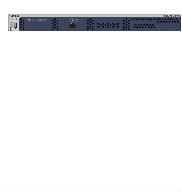
WC7500 and WC7600v2 Front Panel Ports and Slots
The following figure shows the front panel of models WC7500 and WC7600v2. (The label on the right states PROSAFE WC7500 but the front panel for the WC7600v2 is identical.)
|
Digital access point counter |
|
|
|
|
|
USB ports |
Console port |
||||||||||||||
|
|
|
|
|
|
|
|
|
|
|
|
|
|
|
|
|
|
|
|
|
|
|
|
|
|
|
|
|
|
|
|
|
|
|
|
|
|
|
|
|
|
|
|
|
|
|
|
|
|
|
|
|
|
|
|
|
|
|
|
|
|
|
|
|
|
|
|
|
|
|
|
|
|
|
|
|
|
|
|
|
|
|
|
|
|
|
|
|
|
|
|
|
|
|
|
|
|
|
|
|
|
|
|
|
|
|
|
|
|
|
|
|
|
|
|
|
|
|
|
|
|
|
|
|
|
|
|
|
|
|
|
|
|
|
|
|
|
|
|
|
|
|
|
|
|
|
|
|
|
|
|
|
|
|
|
|
|
|
|
|
|
|
|
|
|
|
|
|
|
|
|
|
|
|
|
|
|
|
|
|
|
|
|
|
|
|
|
|
|
|
|
|
|
|
|
|
|
|
|
|
|
|
|
|
|
|
|
|
|
|
|
|
|
|
|
|
|
|
|
|
|
|
|
|
|
|
|
|
|
|
|
|
|
|
|
|
|
|
|
|
|
|
|
|
|
|
|
|
|
|
|
|
LEDs (top to bottom): |
10/100/1000M RJ-45 ports |
SD slot |
Reset button |
Power, Status, |
and LEDs |
|
|
Fan, Stack Maser |
|
|
|
Figure 1. Front panel models WC7500 and WC7600v2
Hardware Descriptions
19

ProSAFE Wireless Controller
The following figure shows a close-up of the left side of the front panel.
|
|
|
Digital access point counter |
|
|
|
|
|
|
|
|
|
|
|
USB ports |
||||||||||
|
|
|
|
|
|
|
|
|
|
|
|
|
|
|
|
|
|
|
|
|
|
|
|
|
|
|
|
|
|
|
|
|
|
|
|
|
|
|
|
|
|
|
|
|
|
|
|
|
|
|
|
|
|
|
|
|
|
|
|
|
|
|
|
|
|
|
|
|
|
|
|
|
|
|
|
|
|
|
|
|
|
|
|
|
|
|
|
|
|
|
|
|
|
|
|
|
|
|
|
|
|
|
|
|
|
|
|
|
|
|
|
|
|
|
|
|
|
|
|
|
|
|
|
|
|
|
|
|
|
|
|
|
|
|
|
|
|
|
|
|
|
|
|
|
|
|
|
|
|
|
|
|
|
|
|
|
|
|
|
|
|
|
|
|
|
|
|
|
|
|
|
|
|
|
|
|
|
|
|
|
|
|
|
|
|
|
|
|
|
|
|
|
|
|
|
|
|
|
|
|
|
|
|
|
|
|
|
|
|
|
|
|
|
|
|
|
|
|
|
|
|
|
|
|
|
|
|
|
|
|
|
|
|
|
|
|
|
|
|
|
|
|
|
|
|
|
|
|
|
|
|
|
|
|
|
|
|
|
|
|
|
|
|
|
|
|
|
|
|
|
|
|
|
|
|
|
|
|
|
|
|
|
|
|
|
LEDs (top to bottom): |
10/100/1000M RJ-45 ports |
Power, Status, Fan, Stack Master |
and LEDs |
Figure 2. Front panel close-up models WC7500 and WC7600v2
From left to right, the front panel of models WC7500 and WC7600v2 show the components that are described in the following table.
Table 3. Front panel components models WC7500 and WC7600v2
Component |
Description |
|
|
Digital counter |
Displays the number of connected access points that are in a healthy state. |
|
|
System LEDs |
From top to bottom: Power LED, Status LED, Fan LED, and Stack Master LED. |
|
These LEDs are described in Table 5 on page 25. |
|
|
Ethernet ports and LEDs |
Four 10/100/1000 Mbps LAN Ethernet port with an RJ-45 connector, left LED, and |
|
right LED. The Ethernet port provides switched N-way, automatic speed negotiating, |
|
auto MDI/MDIX technology. |
|
|
USB ports |
Two USB 2.0 ports for external storage of floor heat maps, saving of the syslogs, and |
|
backing up the configuration. The USB ports support FAT32 file systems. |
SD card slot |
An SD card for saving of the system logs will be supported in a future release. |
|
|
Console port |
RS232 port for connecting to an optional console terminal. The port provides a DB9 |
|
male connector. The default baud rate is 115200 bits/second. |
|
Note: The console port is for debugging under guidance of NETGEAR technical |
|
support only. |
|
|
Reset button |
Using a sharp object, press and hold this button for about 10 seconds until the Status |
|
LED blinks and the wireless controller returns to factory default settings. |
|
If you reset the wireless controller, all configuration settings are lost and the default |
|
password is restored. |
Hardware Descriptions
20

ProSAFE Wireless Controller
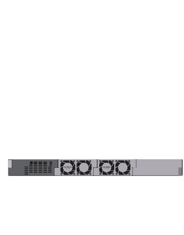
WC7500 and WC7600v2 Back Panel Components
The wireless controller comes with a single internal power supply and internal fans. The back panel provides a Kensington™ lock slot and the AC power supply connector for the 100–240V, 3A, 50–60 Hz power supply.
|
|
|
|
|
Power supply connector |
Kensington lock slot |
||
Figure 3. Back panel models WC7500 and WC7600v2
Attach the power cord to the power supply connector. (The wireless controller does not provide an on/off power switch.)
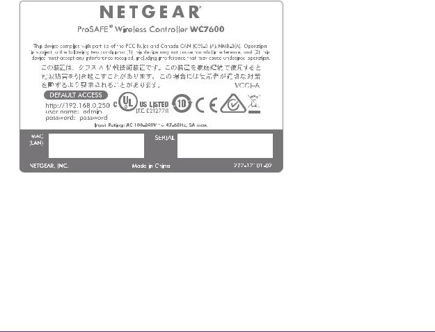
WC7500 and WC7600v2 Product Labels
The product label on the bottom of the wireless controller’s enclosure displays the default IP address, default user name, and default password, as well as regulatory compliance, input power, and other information.
Model WC7500 and model WC7600v2 share the same product label. The actual model number (WC16A for both the WC7500 and the WC7600v2) is stated in the MODEL field.
Figure 4. Product label model WC7500 and model WC7600v2
Hardware Descriptions
21
ProSAFE Wireless Controller
Hardware Models WC7600 and WC9500
The front panel ports, slots, and LEDs, back panel components, and product label of models WC7600 and WC9500 are described in the following sections.
WC7600 and WC9500 Front Panel Ports and Slots
The following figure shows the front panel of models WC7600 and WC9500. (The label on the right states PROSAFE WC9500 but the front panel for the WC7600 is identical.)
Digital access point counter
SFP+ slots and LEDs
|
|
|
|
|
|
|
|
|
|
|
|
|
|
|
|
|
|
|
|
|
|
|
|
|
|
|
|
|
|
|
|
|
|
|
|
|
|
|
|
|
|
|
|
|
|
|
|
|
|
|
|
|
|
|
|
|
|
|
|
|
|
|
|
|
|
|
|
|
|
|
|
|
|
|
|
|
|
|
|
|
|
|
|
|
|
|
|
|
|
|
|
|
|
|
|
|
|
|
|
|
|
|
|
|
|
|
|
|
|
|
|
|
|
|
|
|
|
|
|
|
|
|
|
|
|
|
|
|
|
|
|
|
|
|
|
USB port |
|
|
|
|
|
|
|
|
|
|
|
|
|
||||||
|
|
|
|
|
|
|
|
|
10/100/1000M RJ-45 port |
Console |
port |
||||||||||||||
|
|
|
|
|
|
|
|
|
|
|
|
|
|
|
|
and LEDs |
|
|
|||||||
|
|
|
Reset button |
|
|
|
|
|
|||||||||||||||||
|
|
|
|
|
|
|
|
|
|
|
|
|
|
|
|
||||||||||
|
|
LEDs (top to bottom): |
|
|
|
|
|
|
|
|
|
|
|
|
|
||||||||||
|
|
|
|
|
|
|
|
|
|
|
|
|
|
||||||||||||
Power, Status, |
|
|
|
|
|
|
|
|
|
|
|
|
|
||||||||||||
Fan, Stack Maser |
|
|
|
|
|
|
|
|
|
|
|
|
|
||||||||||||
Figure 5. Front panel models WC7600 and WC9500
The following figure shows a close-up of the left side of the front panel.
Digital access point counter
SFP+ slots and LEDs
|
|
|
|
|
|
|
|
|
|
|
|
|
|
|
|
|
|
|
|
|
|
|
|
|
|
|
|
|
|
|
|
|
|
|
|
|
|
|
|
|
|
|
|
|
|
|
|
|
|
|
|
|
|
|
|
|
|
|
|
|
|
|
|
|
|
|
|
|
|
|
|
|
|
|
|
|
|
|
|
|
|
|
|
|
|
|
|
|
|
|
|
|
|
|
|
|
|
|
|
|
|
|
|
|
|
|
|
|
|
|
|
|
|
|
|
|
|
|
|
|
|
|
|
|
|
|
|
|
|
|
|
|
|
|
|
|
|
|
|
|
|
|
|
|
|
|
|
|
|
|
|
|
|
|
|
|
|
|
|
|
|
|
|
|
|
|
|
|
|
|
|
|
|
|
|
|
|
|
|
|
|
|
|
|
|
|
|
|
|
|
|
|
|
|
|
|
|
|
|
|
|
|
|
|
|
|
|
|
|
|
|
|
|
|
|
|
|
|
|
|
|
|
|
|
|
|
|
|
|
|
|
|
|
|
|
|
|
|
|
|
|
|
|
|
|
|
|
|
|
|
|
|
|
|
|
|
|
|
|
|
|
|
|
|
|
|
|
|
|
|
|
|
|
|
|
|
|
|
|
|
|
|
|
|
|
|
|
|
|
|
|
|
|
|
|
|
|
|
|
|
|
|
|
|
|
|
|
|
|
|
|
|
|
|
|
|
|
|
USB port |
|
|
|
|
|
|
|
|
|
|
|
|
||||||||||||||||||
|
|
|
|
|
|
|
|
10/100/1000M RJ-45 port |
||||||||||||||||||||||||||
|
|
Reset button |
|
|
|
|
||||||||||||||||||||||||||||
|
|
|
|
|
|
and LEDs |
||||||||||||||||||||||||||||
LEDs (top to bottom): |
|
|
|
|
|
|
|
|
|
|
|
|
||||||||||||||||||||||
Power, Status, |
|
|
|
|
|
|
|
|
|
|
|
|
||||||||||||||||||||||
Fan, Stack Maser |
|
|
|
|
|
|
|
|
|
|
|
|
||||||||||||||||||||||
Figure 6. Front panel close-up models WC7600 and WC9500
Hardware Descriptions
22
ProSAFE Wireless Controller
From left to right, the front panel of models WC7600 and WC9500 show the components that are described in the following table.
Table 4. Front panel components models WC7600 and WC9500
Component |
Description |
|
|
Digital counter |
Displays the number of connected access points that are in a healthy state. |
|
|
System LEDs |
From top to bottom: Power LED, Status LED, Fan LED, and Stack Master LED. |
|
These LEDs are described in Table 5 on page 25. |
Reset button |
Using a sharp object, press and hold this button for about 10 seconds until the Status |
|
LED blinks and the wireless controller returns to factory default settings. |
|
If you reset the wireless controller, all configuration settings are lost and the default |
|
password is restored. |
|
|
USB port |
One USB 2.0 port for external storage of floor heat maps, saving of the syslogs, and |
|
backing up the configuration. The USB port supports FAT32 file systems. |
|
|
SFP+ slots and LEDs |
Two SFP+ slots for optional 10GE SFP+ or 1G SFP gigabit interface converters |
|
(GBICs), each slot with an LED. |
Ethernet port and LEDs |
One 10/100/1000 Mbps LAN Ethernet port with an RJ-45 connector, left LED, and |
|
right LED. The Ethernet port provides switched N-way, automatic speed negotiating, |
|
auto MDI/MDIX technology. |
Console port |
RS232 port for connecting to an optional console terminal. The port provides a DB9 |
|
male connector. The default baud rate is 9600 bits/second. |
|
Note: The console port is for debugging under guidance of NETGEAR technical |
|
support only. |
WC7600 and WC9500 Back Panel Components
The wireless controller comes with a single internal power supply but supports an optional second power supply for power redundancy. The power supplies are hot-swappable.
The following figure shows the back panel of the wireless controller with a single internal power supply, the power supply connector, and two double fans.
|
|
|
|
|
|
|
|
|
|
|
|
|
|
|
Removable power supply |
Removable fans |
Slot for |
an optional |
||
Power |
supply connector |
|
second power supply |
|||
Figure 7. Back panel models WC7600 and WC9500
Hardware Descriptions
23
ProSAFE Wireless Controller
From left to right, the back panel of models WC7600 and WC9500 provide the following components:
•Power supply. 100–240V, 5A, 47–63 Hz power supply, which includes the following external components:
-AC power socket. Attach the power cord to this socket. (The wireless controller does not provide an on/off power switch.)
-Power supply with handle. The handle allows for easy removal and insertion of the power supply.
-LED. The power supply LED is lit green when the power supply functions correctly. If the LED is off, power is not supplied to the power supply, or a problem occurred.
•Fans. Two double fans, each of which can be easily exchanged.
•Slot for optional second power supply. The cover plate can be removed so you can insert a second removable power supply for power redundancy.
WC7600 and WC9500 Product Labels
The product label on the bottom of the wireless controller’s enclosure displays the default IP address, default user name, and default password, as well as regulatory compliance, input power, and other information.
Figure 8. Product label model WC7600
Hardware Descriptions
24

ProSAFE Wireless Controller
Figure 9. Product label WC9500
LED Functions (All Models)
The function of each LED is described in the following table. These LEDS apply to all models except where noted otherwise.
Table 5. LED functions for all models
LED |
Status |
Description |
|
|
|
Power LED |
Solid green |
The wireless controller is on. |
|
|
|
|
Off |
The wireless controller is off. |
|
|
If the power LED is not lit when the wireless controller is on, |
|
|
check the connections and check to see if the power outlet is |
|
|
controlled by a wall switch that is turned off (see Power LED Is |
|
|
Not Lit on page 361). |
|
|
|
Status LED |
Solid yellow |
The wireless controller is initializing. After approximately two |
|
|
minutes, when the wireless controller completes its |
|
|
initialization, the Status LED turns solid green. If the Status |
|
|
LED remains solid yellow, the initialization failed (see Status |
|
|
LED Never Turns Off on page 361). |
|
Solid green |
The wireless controller completed its initialization successfully. |
|
|
The Status LED is solid green during normal operation. |
|
|
|
|
Off |
The wireless controller is not receiving power. |
|
|
|
|
Blinking yellow |
Firmware is being upgraded. |
|
|
|
Fan LED |
Solid green |
The fans are functioning correctly. |
|
|
|
|
Solid yellow |
One or more fans are not functioning correctly. |
|
|
|
Hardware Descriptions
25

ProSAFE Wireless Controller
Table 5. LED functions for all models (continued)
LED |
Status |
|
Description |
|
|
|
|
Stack Master LED |
Solid green |
|
The wireless controller is functioning as the master controller in |
Note: Does not |
|
|
a stack. |
|
|
|
|
|
|
|
|
apply to WC7500 |
Solid yellow |
|
The wireless controller is functioning as a slave controller in a |
|
|
|
stack. |
|
|
|
|
SFP slot LEDs |
Solid green |
|
The slot is operating at 10G. |
Note: Does not |
|
|
|
Blinking green |
Data is being transmitted or received at 10G. |
||
apply to WC7500 |
|
|
|
|
|
|
|
and WC7600v2 |
Solid yellow |
|
The slot is operating at 1G. |
|
|
|
|
|
Blinking yellow |
Data is being transmitted or received at 1G. |
|
|
|
|
|
Left Ethernet |
Off |
|
The port is not connected to a powered-on Ethernet device |
port LED |
|
|
(see Ethernet Port LEDs Are Not Lit on page 361). |
|
|
|
|
|
WC7500 |
Solid green |
The port is operating at 1000 Mbps. |
|
and |
|
|
|
Blinking green |
Data is being transmitted or received at 1000 Mbps. |
|
|
WC7600v2 |
||
|
|
|
|
|
WC7600 |
Solid green |
The port is operating at 1000 Mbps. |
|
and |
|
|
|
Solid yellow |
The port is operating at 100 Mbps or 10 Mbps. |
|
|
WC9500 |
||
|
|
|
|
Right Ethernet |
Off |
|
The port is not connected to a powered-on Ethernet device |
port LED |
|
|
(see Ethernet Port LEDs Are Not Lit on page 361). |
|
|
|
|
|
WC7500 |
Solid yellow |
The port is operating at 100 Mbps or 10 Mbps. |
|
and |
|
|
|
Blinking yellow |
Data is being transmitted or received at 100 Mbps or 10 Mbps. |
|
|
WC7600v2 |
||
|
|
|
|
|
WC7600 |
Solid green |
The port is connected to a powered-on Ethernet device. |
|
and |
|
|
|
Blinking green |
Data is being transmitted or received. |
|
|
WC9500 |
||
|
|
|
|
Wireless Controller System Components
A wireless controller system consists of one or more wireless controllers and a collection of access points that are organized into groups based on location or network access.
The wireless controller system can include a single wireless controller or a group of up to three stacked wireless controllers that can function in a redundant configuration1.
The wireless controller system supports the following NETGEAR ProSAFE access point models:
•WAC740 ProSAFE 4x4 Dual-Band Wireless AC Access Point
•WAC730 ProSAFE 3x3 Dual-Band Wireless AC Access Point
•WAC720 ProSAFE 2x2 Dual-Band Wireless AC Access Point
1.Model WC7500 does not support stacking and redundancy.
Hardware Descriptions
26

ProSAFE Wireless Controller
•WN370 ProSAFE Wall Mount Wireless N Access Point
•WND930 Outdoor Dual Band Wireless-N
•WNDAP660 ProSAFE Premium 3x3 Dual Band Concurrent Wireless-N Access Point
•WNDAP380R ProSAFE Dual Band Wireless-N Access Point with RFID support
•WNDAP360 ProSAFE Dual Band Wireless-N Access Point
•WNDAP350 ProSAFE Dual Band Wireless-N Access Point
•WNAP320 ProSAFE Wireless-N Access Point
•WNAP210v2 ProSAFE Wireless-N Access Point
Supported NETGEAR Access Points
You can connect access points to the wireless controller either directly with an Ethernet cable through a router or switch, or remotely through a VPN network. After you use the automatic discovery process and add access points to the managed access point list on the wireless controller, the wireless controller converts the standard access points to dependent access points by pushing firmware to the access points. From then on, you can centrally manage and monitor the access points.
The following table lists the minimum firmware versions that must run on the standalone access points before you convert them to managed access points. If your access point runs a firmware version that is earlier than the minimum firmware version, first upgrade the access point to the minimum firmware version or a later version.
Table 6. Minimum firmware versions
Access Point Model |
Minimum Firmware Version on Standalone Access Point |
|
|
WAC740 |
Model WAC740 cannot function as a standalone access point. This model can be |
|
used only as a controller-managed access point. |
|
|
WAC730 |
All firmware versions are supported. |
|
|
WAC720 |
All firmware versions are supported. |
|
|
WN370 |
Model WN370 cannot function as a standalone access point. This model can be used |
|
only as a controller-managed access point. |
WND930 |
2.0.4 or a newer version is supported. |
|
|
WNDAP660 |
2.0.2 or a newer version is supported. |
|
|
WNDAP380R |
All firmware versions are supported. |
|
|
WNDAP360 |
2.1.6 or a newer version is supported. |
|
|
WNDAP350 |
2.1.7 or a newer version is supported. |
|
|
WNAP320 |
2.1.1 or a newer version is supported. |
|
|
WNAP210v2 |
All firmware versions are supported. |
|
|
Hardware Descriptions
27

ProSAFE Wireless Controller
A wireless controller system supports the following access points:
•WAC740 ProSAFE 4x4 Dual-Band Wireless AC Access Point
-Supports concurrently 802.11a, 802.11b, 802.11g, 802.11n, and 802.11ac network devices.
-Operates concurrently in the 2.4 GHz and 5 GHz radio bands.
-Supports 4x4 multi-user multiple input, multiple output (MU-MIMO).
-Supports speeds of up to 1.7 Gbps for 802.11ac network devices.
-Supports Power over Ethernet plus (PoE+) with a power consumption that complies with the 802.3at standard.
-Accepts optional antennas.
For product documentation and firmware, visit netgear.com/support/product/WAC740.
•WAC730 ProSAFE 3x3 Dual-Band Wireless AC Access Point
-Supports concurrently 802.11a, 802.11b, 802.11g, 802.11n, and 802.11ac network devices.
-Operates concurrently in the 2.4 GHz and 5 GHz radio bands.
-Supports 3x3 multiple input, multiple output (MIMO).
-Supports speeds of up to 1300 Mbps for 802.11ac network devices.
-Supports Power over Ethernet (PoE) with a power consumption that complies with the 802.3af standard.
-Accepts optional antennas.
For product documentation and firmware, visit netgear.com/support/product/WAC730.
•WAC720 ProSAFE 2x2 Dual-Band Wireless AC Access Point
-Supports concurrently 802.11a, 802.11b, 802.11g, 802.11n, and 802.11ac network devices.
-Operates concurrently in the 2.4 GHz and 5 GHz radio bands.
-Supports 2x2 multiple input, multiple output (MIMO).
-Supports speeds of up to 867 Mbps for 802.11ac network devices
-Supports Power over Ethernet (PoE) with a power consumption that complies with the 802.3af standard.
-Accepts optional antennas.
For product documentation and firmware, visit netgear.com/support/product/WAC720.
•WN370 ProSAFE Wall Mounted Wireless-N Access Point
-Supports concurrently 802.11b, 802.11g, and 802.11n network devices.
-Operates in the 2.4 GHz radio band.
-Supports speeds of up to 300 Mbps for 802.11n network devices.
-Supports Power over Ethernet (PoE) with a power consumption that complies with the 802.3af standard.
Hardware Descriptions
28

ProSAFE Wireless Controller
For product documentation and firmware, visit netgear.com/support/product/WN370.
•WND930 Outdoor Dual Band Wireless-N
-Supports 802.11a, 802.11b, 802.11g, and 802.11n network devices.
-Operates concurrently in the 2.4 GHz and 5 GHz radio bands.
-Supports speeds of up to 300 Mbps for 802.11n network devices.
-Supports Power over Ethernet (PoE) with a power consumption that complies with the 802.3af or 802.3at standards.
For product documentation and firmware, visit netgear.com/support/product/WND930.
•WNDAP660 ProSAFE Premium 3x3 Dual Band Concurrent Wireless-N Access Point
-Supports 802.11a, 802.11b, 802.11g, and 802.11n network devices.
-Operates concurrently in the 2.4 GHz and 5 GHz radio bands.
-Supports 3x3 multiple input, multiple output (MIMO).
-Supports speeds of up to 450 Mbps for 802.11n network devices.
-Supports Power over Ethernet (PoE) with a power consumption that complies with the 802.3at standard.
Note: If your network does not include a PoE device that can provide the WNDAP660 access point with PoE power according to the 802.3at standard, you can instead use two ports of a PoE device that complies with the 802.3af standard. (The WNDAP660 access point provides two Ethernet ports that accept PoE.)
-Accepts optional antennas.
For product documentation and firmware, visit netgear.com/support/product/WNDAP660.
•WNDAP380R ProSAFE Dual Band Wireless-N Access Point with RFID support
-Supports 802.11a, 802.11b, 802.11g, and 802.11n network devices.
-Operates concurrently in the 2.4 GHz and 5 GHz radio bands.
-Supports Power over Ethernet (PoE) with a power consumption of up to 10.51W.
-Accepts an RFID module for support of RFID devices and tags.
For product documentation and firmware, visit netgear.com/support/product/WNDAP380R.
•WNDAP360 ProSAFE Dual Band Wireless-N Access Point
-Supports 802.11a, 802.11b, 802.11g, and 802.11n network devices.
-Operates concurrently in the 2.4 GHz and 5 GHz radio bands.
-Supports Power over Ethernet (PoE) with a power consumption of up to 10.51W.
-Accepts optional antennas.
For product documentation and firmware, visit netgear.com/support/product/WNDAP360.
Hardware Descriptions
29

ProSAFE Wireless Controller
•WNDAP350 ProSAFE Dual Band Wireless-N Access Point
-Supports 802.11a, 802.11b, 802.11g, and 802.11n network devices.
-Operates concurrently in the 2.4 GHz and 5 GHz radio bands.
-Supports Power over Ethernet (PoE) with a power consumption of up to 10.75W.
-Accepts optional antennas.
For product documentation and firmware, visit netgear.com/support/product/WNDAP350.
•WNAP320 ProSAFE Wireless-N Access Point
-Supports 802.11b, 802.11g, and 802.11n network devices.
-Operates in the 2.4 GHz radio band.
-Supports Power over Ethernet (PoE) with a power consumption of up to 5.8W.
-Accepts optional antennas.
For product documentation and firmware, visit netgear.com/support/product/WNAP320.
•WNAP210v2 ProSAFE Wireless-N Access Point
-Supports 802.11b, 802.11g, and 802.11n network devices.
-Operates in the 2.4 GHz radio band.
-Supports Power over Ethernet (PoE) with a power consumption of up to 5.8W.
-Operates in the 2.4 GHz radio band.
For product documentation and firmware, visit netgear.com/support/product/WNAP210v2.
Note: Model WNAP210v1 cannot function in a wireless controller system, but model WNAP210v2 can.
Supported NETGEAR Antennas
A wireless controller system supports the following antennas:
•ANT2409 ProSAFE Indoor/Outdoor 9 dBi Omni-directional Antenna
-9 dBi omni-directional antenna for indoor or outdoor use
-WiFi signal 802.11g
-Frequency range 2400–2485 MHz
-Maximum range 11.5 km (7.2 miles)
-Polarization vertical
For product documentation and firmware, visit netgear.com/support/product/ANT2409v2.
•ANT224D10 ProSAFE 10 dBi 2x2 Indoor/Outdoor Directional Antenna
-10 dBi directional antenna for indoor or outdoor use
-WiFi signal 802.11n
Hardware Descriptions
30
Loading...