


SmartCraft Gateways
For single and dual engine applications
Installation and
Operation Manual
w w w . n a v m a n . c o m
NAVMAN

IMPORTANT SAFETY INFORMATION
Please read carefully before installation and use.
DANGER |
This is the safety alert symbol. It is used to alert you to potential |
|
personal injury hazards, Obey all safety messages that follow this |
||
|
|
symbol to avoid possible injury or death. |
|
|
|
! |
WARNING |
WARNINGindicatesapotentiallyhazardoussituationwhich,ifnot |
avoided, could result in death or serious injury |
||
|
|
|
! |
CAUTION |
CAUTION indicates a potentially hazardous situation which, if not |
avoided, could result in minor or moderate injury. |
||
|
|
|
CAUTION |
CAUTION used without the safety alert symbol indicates a |
|
potentially hazardous situation which, if not avoided, may result |
||
|
|
in property damage. |
|
|
|
FCC Statement
Note: This equipment has been tested and found to comply with the limits for a Class B digital device, pursuant to Part 15 of the FCC Rules. These limits are designed to provide reasonable protection against harmful interference in a normal installation. This equipment generates, uses and can radiate radio frequency energy and, if not installed and used in accordance with the instructions, may cause harmful interference to radio communications. However, there is no guarantee that interference will not occur in a particular installation. If this equipment does cause harmful interference to radio or television reception, which can be determined by turning the equipment off and on, the user is encouraged to try to correct the interference by one or more of the following measures:
Reorient or relocate the receiving antenna.
Increase the separation between the equipment and receiver.
Connect the equipment into an output on a circuit different from that to which the receiver is connected.
Consult the dealer or an experienced technician for help.
A shielded cable must be used when connecting a peripheral to the serial ports.
Industry Canada
Operation is subject to the following two conditions: (1) this device may not cause interference, and (2) this device must accept any interference, including interference that may cause undesired operation of the device.

Contents |
|
1Introduction.......................................................................................................................................... |
4 |
1-1SmartCraftdataavailablefromdifferentengines ................................. |
4 |
1-2Whatcomeswithyourgateway?.................................................. |
5 |
2Installation............................................................................................................................................ |
6 |
2-1ConnectingthegatewaytotheSmartCraftsystem ...............................6 2-2ConnectingthegatewaytotheNavmaninstrument..............................7 2-3Installation .......................................................................7
3OperationwithaNavmanFISH4380....................................................................................................... |
8 |
3-1SettinguptheFISH4380forSmartcraft...........................................9 3-2SmartCraftenginedatadisplays.................................................10 3-3Trollcontrol .....................................................................11 3-4Trimindicator ...................................................................12 3-5Enginefaultalarms..............................................................12 3-6Enginefaultlists.................................................................13 3-7SmartCraftsetupdata...........................................................14 3-8SmartCraftcalibration...........................................................16
4OperationwithaNavmanTRACKFISH6600........................................................................................... |
18 |
4-1SettinguptheTRACKFISH6600forSmartcraft...................................19 4-2SmartCraftenginedatadisplays.................................................19 4-2-1Tankstatusdisplay.............................................................20 4-2-2Customisingtheenginedatadisplays .........................................20 4-3Trollcontrol .....................................................................21 4-4Trimindicator ...................................................................21 4-5Enginefaultalarms..............................................................22 4-6Enginefaultlists.................................................................22 4-7SmartCraftsetupdataandcalibrations..........................................23
5OperationwithaNavmanFISH4600..................................................................................................... |
27 |
5-1SettinguptheFISH4600forSmartcraft..........................................28 5-2SmartCraftenginedatadisplays.................................................28 5-3Trollcontrol .....................................................................30 5-4Trimindicator ...................................................................30 5-5Enginefaultalarms..............................................................31 5-6Enginefaultlists.................................................................31 5-7SmartCraftsetupdataandcalibrations ..........................................32
AppendixA-Specifications..................................................................................................................... |
36 |
AppendixB-Troubleshooting................................................................................................................. |
36 |

1 Introduction
The Navman SmartCraftTM gateway connects one or two SmartCraft capable Mercury petrol/gasoline engines to a SmartCraft capable Navman instrument, such as the FISH 4380, FISH 4600 or TRACKFISH 6600. The single gateway is for single engines, the dual gateway is for twin engines.
Adding the gateway extends the functions of the Navman instrument, allowing the instrument to:
Display engine data, such as speed, RPM, pressures, tank levels.
Control troll speed and display trim.
Sound an alarm if it detects an abnormal engine condition.
This manual describes:
How to install a Navman SmartCraft gateway.
How to use the SmartCraft functions of a Navman SmartCraft capable instrument. Refer to the separate Navman instrument
Installation and Operation Manual for information on how to install and use the instrument.
The engine data available in a system depends on the type of engine used (see section 1-1). The gateway replaces any fuel flow sensors that might be plugged into the Navman
instrument .
It is vital to read this document and the associated SmartCraft and Navman installation and operation manuals before installing or using the system.
1-1 SmartCraft data available from different engines
The SmartCraft engine data available in a system depends on the type of engine. SmartCraft is a digital engine network provided on some later model (2002 +) Mercury and Mariner Engines, both in-board and out-board.
Engine data available
Steering Angle Fuel level
Oil temperature Oil Pressure Engine Trim Water Pressure
Engine temperature Fuel Flow
Fuel Level Engine voltage
Pitot water (boat) speed RPM
|
|
|
|
|
Engine type |
|
|
|
|
|
|
4 Stroke 30 - 60 |
V-6 EFI |
Optimax 75115 |
Optimax 135-250 |
Optimax 225 DTS |
Verado |
Mercruiser 4.3 L |
Mercruiser 5.0 L |
Mercruiser 5.7 L |
Mercruiser 6.2 L |
Mercruiser 8.1 L |
496 HO |
4 |
NAVMAN SmartCraft Gateways Installation and Operation Manual |

1-1-1 Tanks and sensors
Engines can have optional level sensors fitted:
A two-stroke engine can have one sensor fitted to its oil tank, and one additional sensor fitted to a fuel, oil, water or waste tank.
A four stroke engine can have one or two sensors fitted to its fuel, water or waste tanks.
If level sensors are fitted: the tank levels can be displayed; there are alarms for low tank levels; the tanks must be set up and calibrated (see following sections:
FISH 4380 : Section 3-8-1 TRACKFISH 6600 : Section 4-7-1 FISH 4600 : Section 5-7-1
1-2 What comes with your gateway?
Built-in cable to the Navman instrument, 1 m (3.3 ft) long
Built-in cable to the SmartCraft system, 300 mm (1 ft.) long
SmartCraft Gateway
Gateway LEDS:
NAV (orange): Flashes fast when the gateway is exchanging data with the Navman instrument and the engine key is on.
PWR (green): On when power and the engine key are on.
CAN (red): Flashes fast when the gateway is exchanging data with the SmartCraft engine(s) and the engine key is on.
Holes for mounting screws |
|
Also supplied: |
• |
Two mounting screws (8 gauge x 5/8 inch, |
|
|
|
Pan pozi, self tapping, stainless steel); |
|
• |
Warranty card; |
|
• |
This manual. |
Optional extras for SmartCraft
AA002237
Power/fuel splitter cable
A power/fuel splitter cable (‘Y’ cable) is required for Navman instruments that do not have a separate fuel sensor connector (such as the FISH 4380, see section 2-2). This cable is included in hardware packages AA005022 and AA005023 and is also available separately from your Navman dealer.
Also see Appendix-C
NAVMAN SmartCraft Gateways Installation and Operation Manual |
5 |

2 Installation
A system in a boat comprises:
a.One or two SmartCraft capable petrol/ gasoline engines; the data available depends on engine type and the sensors fitted (see section 1-1).
b.A single or dual engine gateway.
c.A SmartCraft capable Navman instrument, such as the FISH 4380, FISH 4600 or TRACKFISH 6600.
d.Other optional Navman instruments and SmartCraft displays. See Appendix-C
CAUTION
Correct installation is critical to the performance of the unit. Before starting installation, it is vital to read this manual and the documentation that comes with the other parts. Then plan the installation and select where the equipment and cables will be located.
CAUTION
Ensure that any holes that you cut will not weaken the boat’s structure. If in doubt, consult a qualified boat builder.
2-1 Connecting the gateway to the SmartCraft system
Using a Navman cable adaptor: Use a Navman cable adaptor in a single engine system which does not have optional SmartCraft displays. However, a SmartCraft junction box should be used if future expansion of the SmartCraft system is planned.
SmartCraft harness 879982T-x |
SmartCraft cable adaptor 892452A01 |
(x = length in feet) |
|
Petrol |
Single engine gateway |
engine |
|
Using a SmartCraft junction box: Connect the gateway to a SmartCraft Junction box in a twin engine system or in any system with optional SmartCraft displays.
SmartCraft harness 879981T-x Petrol (x = length in feet) engine
Petrol |
|
SmartCraft junction box |
|
engine |
Optional |
||
878492B-4 |
|||
|
Fit optional SmartCraft displays, or fit Mercury weather cap 859318T-2
Single or dual engine gateway
There must be two SmartCraft Terminators in any SmartCraft Installation. The Mercury harness 84-879982T-x has two terminators built-in; the Mercury harness 84-879981T-x has one terminator built-in.Terminators must be positioned at the furthermost ends of the SmartCraft network.
Refer to a Mercury SmartCraft manual, such as Wiring for SmartCraft Gauges (Mercury part 90-879939), for details of installation configurations and requirements, alternative termination methods and additional SmartCraft components such as harnesses, junction boxes and terminators. Also see Appendix C
To use the SmartCraft functions, install the SmartCraft gateway (see section 2), then go to the System setup menu on the Navman Instrument and turn SmartCraft to On (See Setup > System menu).
6 |
NAVMAN SmartCraft Gateways Installation and Operation Manual |
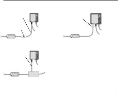
2-2 Connecting the gateway to the Navman instrument
For a Navman instrument without a white fuel sensor connector (such as a FISH 4380):
For a Navman instrument with a white fuel sensor connector (such as a FISH 4600 or TRACKFISH 6600):
Power/fuel splitter |
FISH 4380 |
Plug gateway into |
FISH 4600, |
cable (‘Y’ cable) |
|
TRACKFISH |
|
|
white connector |
||
|
|
6600 |
|
|
|
|
|
Plug gateway into |
|
|
|
white connector |
Other wiring, |
|
Other wiring, |
|
|
||
|
refer to the |
|
refer to the |
|
instrument’s |
|
instrument’s |
|
manual |
|
manual |
For any Navman instrument, using a NavBus junction box to connect to power/data cable (black power connector):
Power/data |
Other wiring, |
cable |
refer to the |
|
instrument’s |
|
manual |
 NavBus
junction box
The wires from the gateway to the Navman instrument cable can be connected to the instrument’s power/data cable. This option is not normally necessary. For more information, refer to your Navman dealer.
Cut white connector off gateway cable. Connect five gateway cable wires (red, black, blue, orange, brown) to the same colour wires in the power/data cable. An optional Navman NavBus junction box simplifies wiring.
2-3 Installation
1Plan the installation: select where the equipment and wiring will be installed. Ensure that gateway can be located on a panel near the Navman instrument, where it will not interfere with the operation of the boat. (eg: cables are long enough for the installation planned)
2Screw the gateway to the panel using the screws provided.
3Connect the gateway (see sections 2-1 and 2-2). Secure the cables at regular intervals.
4Power up, set up and test the system. Check the gateway LEDs:
NAV (orange): Flashes fast when gateway is exchanging data with the Navman instrument and the engine key is on.
PWR (green): On when power and the engine key are on.
CAN (red): Flashes fast when gateway is exchanging data with the SmartCraft engine(s) and the engine key is on.
Important:
1Do not connect any Navman fuel sensors to the Navman instrument.
2It is not necessary to wire any Navman instrument for auto power on.
3The Navman SmartCraft capable instrument sends SmartCraft data to other
Navman instruments connected by NavBus. To connect other instruments by NavBus, see the instrument’s installation and operation manual. Turn NavBus on in all Navman
instruments connected by NavBus; for example, for a Fish 4380, in the Comms setup menu, turn NavBus to On.
4A gateway does not provide data for system link gauges.
5To use speed troll control, the Navman instrument must have a Navman paddlewheel speed sensor connected.
NAVMAN SmartCraft Gateways Installation and Operation Manual |
7 |

3 Operation with a Navman FISH 4380
Before a SmartCraft gateway is connected, the FISH 4380 functions normally, with no SmartCraft functions. When a SmartCraft gateway is connected and SmartCraft is turned On (see section 3-1),
SmartCraft functions become available and some standard functions change.
SmartCraft features
Data displays
Engine performance and tank level displays.....................................................................................................................
See section 3-2
Troll control
Automatically maintains a set engine idle RPM or idle boat speed ..........................................................................
See section 3-3
Trim indicator
Displays the trim angle when engine trim is adjusted...................................................................................................
See section 3-4
Alarms
SmartCraft engine fault alarms...............................................................................................................................................
See section 3-5
Engine fault list, a list of active SmartCraft engine fault alarms..................................................................................
See section 3-6
Engine fault history, a list of past SmartCraft engine fault alarms.............................................................................
See section 3-6
Tank low level alarms..................................................................................................................................................................
See section 3-2
Setup data and calibrations
SmartCraft setup data................................................................................................................................................................
See sections 3-1 and 3-7
SmartCraft calibrations,Tanks,Trim and Steering angle................................................................................................
See section 3-8
The SmartCraft data available depends on the engine type and the sensors fitted (see section 1-1). To disable the SmartCraft functions, turn SmartCraft to Off (see section 3-1); the instrument will now use any
Navman fuel sensors which are connected.
To use the SmartCraft functions and not the sonar functions, turn Sonar to Off (see section 3-1).
Changes to standard functions with SmartCraft
 key: When using troll control, pressing
  can display the troll window. Press
  a second time to display the normal menu of options.
Fuel display: The fuel display functions normally, with fuel and speed data coming from the SmartCraft system rather than from separate sensors connected to the FISH 4380.
Fuel setup options:
If no fuel tanks have an optional level sensor fitted (see section 1-1-1), then the Smartcraft fuel flow is used to calculate fuel remaining. The fuel setup data is the same as the standard FISH 4380. You must tell the FISH 4380 when you add or remove fuel (see the FISH 4380 Installation and Operation manual).
If each fuel tank has an optional level sensor fitted (see section 1-1-1), then these tank levels are
used to calculate fuel remaining. In the Fuel display, Used changes to Trip used, and the only fuel setup option is Clear trip used. Trip used measures the volume of fuel used until it is reset to zero by selecting Clear trip used in the fuel setup menu. You do not tell the FISH
4380 when you add or remove fuel.
8 |
NAVMAN SmartCraft Gateways Installation and Operation Manual |

Engine hours: Engine hours on the Log display come from the SmartCraft system. It can not be reset.
Simulate mode: Data from the SmartCraft engine(s) and sensors is simulated in Simulate mode. The SmartCraft features simulated will probably differ from the features available in your system.
For more information, see the FISH 4380 Installation and Operation manual.
3-1 Setting up the FISH 4380 for Smartcraft
These features can be used only when the optional single or twin engine SmartCraft Gateway has been installed.
Press  twice to display the Setup menu, then select SmartCraft.
Press  to select On or Off
Note: NavBus will be turned on when SmartCraft is turned on.
Sonar
Select:
Off: The sonar transducer and the sonar functions are disabled. Choose Off to use the instrument’s SmartCraft functions only,
On: Normal sonar operation.
SmartCraft
Select:
Off: The SmartCraft functions and NavBus are disabled. The instrument will now use any Navman fuel sensors which are connected.
On: Normal SmartCraft operation.
NAVMAN SmartCraft Gateways Installation and Operation Manual |
9 |

3-2 SmartCraft engine data displays
To display the SmartCraft data, press  and select SmartCraft, then press
  ,
,  or
or 
or to select one of the four SmartCraft displays, shown below.
For the Small, Medium and Large gauges:
The factory default has gauges appropriate to the type of engine. To change what gauges are displayed, see section 3-7: Gauge setup.
Small: Six small ‘analogue’ gauges:
Header data
Large: Two large ‘analogue’ gauges
If the boat has twin engines, the red needle or number shows port data, green shows starboard data.
The gauges can be set up to be analogue
(dial) or digital (number) (see section 3-7:
Gauge type and Speed range).
Each display has three items of header data. To select what data is displayed, see section 3-7: Header setup.
Medium: Two medium & two small ‘analogue’ gauges
Tanks: Tank levels (see next page)
10 |
NAVMAN SmartCraft Gateways Installation and Operation Manual |
Tank level display
The tank level display shows the levels from the optional level sensors in one or two tanks per engine (see section 1-1-1).
Note:
Each tank must be set up and calibrated (see section 3-8-1).
An alarm can be set to sound if the level in a tank is low (see section 3-8-1). These alarms are in addition to any SmartCraft engine fault low level alarms (see section 3-5).
3-3 Troll control
Troll control allows adjustment of the engine’s idle speed from the Navman instrument. Troll control automatically controls the engine idle speed to maintain a set engine RPM or boat speed.
To use troll control, set Troll window to On idle or Always and set Troll mode to
Speed or RPM (see section 3-7). To use speed troll control, set Speed type to Paddle (see
section 3-7).
To prohibit troll control, set Troll window to Never (see section 3-7).
Engaging troll control
1Set the throttle(s) to idle and the engine(s) in gear. From a main display, press  to display the Troll control window (see right).
2Press  or
or  to set the desired RPM or boat speed (see notes 1 and 2).
3Press  to engage troll control. The FISH
4380 automatically controls RPM or speed. Or, press  to leave troll control disengaged.
Changing RPM or speed while troll control engaged
1From a main display, press  to display the troll window.
2Press  or
or  to change the desired RPM or boat speed (see notes 1 and 2).
3Press  .
.
Disengaging troll control
Either move the throttle from idle, or:
1From a main display, press  to display the troll window.
2Press  to disengage troll control.
Or, press  to leave troll control engaged.
Note:
1The range of engine idle RPM adjustment available for both RPM and speed mode depends one engine type. Generally this is between 600 and 1000 RPM.
2In speed troll control, the boat might not reach the desired speed if the maximum RPM available for troll control is too low or if conditions are bad.
3Troll control is not available on some MerCrusier™ engines.
NAVMAN SmartCraft Gateways Installation and Operation Manual |
11 |
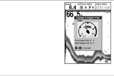
3-4 Trim indicator
When the engine trim is adjusted, a trim popup window can show the new trim angle. To see this window or not, set Trim popup to On or Off (see section 3-7). The window will automatically disappear after two seconds, or else press  or
or  to make the window disappear.
Before use, calibrate trim (see section 3-8-2).
3-5 Engine fault alarms
There are many SmartCraft engine fault alarms. These alarms operate just like the other alarms in the Navman instrument; when the alarm sounds, press  to mute the alarm:
Low reserve oil. Low remote oil. RPM over speed. Low oil pressure.
High engine voltage. Low engine voltage.
A Navman instrument’s low battery alarm measures the voltage the instrument; the above two alarms measure the voltage at the engine.
Low block (water) pressure. Engine overheat.
Low drive lube. (MerCrusier stern drive only).
Water in fuel.
Engine GuardianTM active: The Engine Guardian has detected a fault. The fault is displayed with the alarm.
Engine communication lost: The Navman instrument can not receive engine data from the SmartCraft gateway.
Check engine: There are many other engine fault alarms. When one of these alarms sounds, the alarm Check engine is displayed. For more information about the alarm, display the list of active alarms or the alarm history (see section 3-6).
Notes:
1For help when an SmartCraft alarm occurs, contact your Mercury dealer.
2These SmartCraft alarms are always on. The alarm values are determined by the engine type.
3A list of active faults and a fault history can be displayed (see section 3-6).
12 |
NAVMAN SmartCraft Gateways Installation and Operation Manual |
 Loading...