


NAVMAN
NAVMAN |
F440 |

Contents |
|
Introduction ...................................................................................................................................... |
6 |
Specifications .................................................................................................................................. |
6 |
Installation ........................................................................................................................................ |
7 |
Location ........................................................................................................................................ |
7 |
Installation – The Transducer .................................................................................................. ....... |
8 |
• Transom Mount Transducer ...................................................................................................... |
8 |
Location ................................................................................................................................. |
8 |
Mounting ................................................................................................................................ |
8 |
• Other Types of Transducers ..................................................................................................... |
9 |
Wiring connection ........................................................................................................................... |
9 |
Electrical protection ..................................................................................................................... |
9 |
Operation ........................................................................................................................................ |
10 |
Introduction ................................................................................................................................ |
10 |
Primary functions and quick operation introduction ................................................................. |
10 |
Menu selection system ............................................................................................................. |
10 |
Display and Operating Modes ..................................................................................................... |
11 |
Echo mode ........................................................................................................................ |
11 |
Autofish mode ................................................................................................................... |
11 |
Analogue-scope function ................................................................................................. |
12 |
Navigate Mode ........................................................................................................... |
12 |
Changing the mode of operation ............................................................................................... |
13 |
Range function .............................................................................................................................. |
13 |
Setting the display range ........................................................................................................... |
13 |
Gain function ................................................................................................................................. |
14 |
Setting the gain .......................................................................................................................... |
14 |
Display scroll speed ...................................................................................................................... |
15 |
Setting the scroll speed ............................................................................................................. |
15 |
Alarms ............................................................................................................................................. |
16 |
Anchor Drag Alarm .................................................................................................................... |
16 |
Setting the alarms ...................................................................................................................... |
16 |
Setup Menu ..................................................................................................................................... |
17 |
Changing the setup functions .................................................................................................... |
17 |
Setup Menu – Speed & Temperature (FISH440 only) ............................................................... |
18 |
Changing the speed & temperature setup ................................................................................ |
18 |
Troubleshooting ............................................................................................................................ |
19 |
NAVMAN Fishfinder User Manual |
F4X0/ENG/1A |
5 |
Introduction
Thank you for purchasing a NAVMAN 400 series fishfinder. The 400 series is a powerful, yet easy to use sonar fish and bottom depth detector. Please read this manual carefully before installing and using your fishfinder. This manual deals with both the FISH400 and FISH440. The more you know and understand about the capabilities of the unit, the better it will perform for you.
Specifications for 400 Series
•Dimensions
132 mm W(max) x 133 mm H x 46 mm D
•Depth Capability
180 metres, 600 feet
•Transducer Type
Aquatic transom-mount single beam. Thru hull transducer options are also available.
•Operating Frequency
200 KHz
•Transducer Angle
15 degrees
•Receiver Sensitivity
30 micro volts RMS
•Power Output
400 watts RMS (3200 watts peak-to-peak) maintained within 10% down to 10.5 volts.
•Display Size
100mm (4¼") Diagonal. 82 mm x 76 mm (3¼" x 3")
•Display Type
STN temperature compensated
•Display Matrix
100 x 64 pixels
•Input Voltage
10 to 18 volts DC @ 150 mA max. (lights on)
•Backlighting
Even illumination. Seven levels plus off.
•Operation Temperature
0°C to 40°C ambient ( 32°F to 104°F )
Additional FISH440 Specifications
• |
Boat Speed |
• |
Log |
|
0.0–50.0 kts, mph, kph user selectable |
|
Records up to 9999.9 nm, km, stored in |
• |
Water Temperature |
|
memory, resetable. |
|
0.0–40.0°C (32.0–99.0°F) user selectable |
• |
Power Output |
|
|
|
440 watts RMS (3500 watts peak to peak) |
|
|
|
maintained within 10% down to 10.5 volts. |
Display is backlit for |
|
Active alarms indication |
Night Operation |
|
F=Fish, D=Deep, S=Shallow |
|
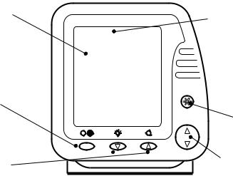
NAVMAN |
FISH400 |
Power On/Off
Menu Exit
Enter Menu Mode Advance to Next Menu
Backlighting On/Off
Change Value Down 
Alarms On/Off |
Move Through Menu Items |
Change Value Up |
|
6 |
NAVMAN Fishfinder User Manual |
Installation
Location
The FISH400 and FISH440 are water resistant and may be mounted and operated in many positions thanks to its compact and robust bracket, associated with a swivel support.
Note
It may be advisable to install the transducer and wiring before finalising the location of the display head and bracket.
When installing the display head, select a position where it will be:
•at least 300 mm ( 12" ) away from the compass.
•at least 300 mm ( 12" ) away from any radio transmitter, such as the VHF.
•easy to read by the helmsman and crew while under way.
•protected from physical damage during rough sea passages.
•have easy access to the 12 volt power source.
•convenient to route the transducer cables.
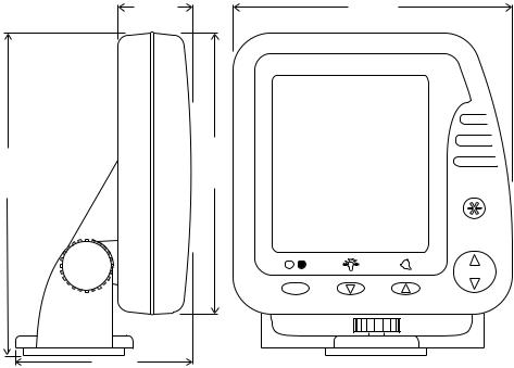
35.0 (1.4") |
132.0 (5.2") |
 NAVMAN FISH400
149.0 (5.9") |
133.0 (5.2") |
81.5 (3.2")
NAVMAN Fishfinder User Manual |
7 |
Installation – The Transducer
Read this section carefully before attempting the transducer installation. Remember, the transducer location is the most critical part of the installation. If this is not done properly, the transducer can’t perform at its designed potential. Therefore the performance of the fishfinder, especially at higher speeds, will not be satisfactory.
• Transom Mount Transducer
Location
The transducer can be installed on any outboard or sterndrive powered boat. The transom mount transducer has a safety “kick up” mounting bracket to help minimise damage to the transducer should it impact the bottom or floating debris in the water.
Select a position for the transducer that will:
•allow the transducer a smooth flow of water over its surface at all times.
•ensure a mount as deep in the water as possible.
•be clear of any interference from the trailer when launching or retrieving the boat.
•be away from planing strakes or other projections from the hull that may cause aerated water to flow over the face of the transducer.
•be away from the propeller
•be at least 150 mm ( 6" ) away from the keel of the boat.
Poor Location
Poor Angle |
Good Location and Angle |
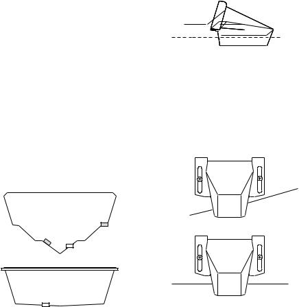
Mounting
Once the best location of the transducer is determined, hold the transducer and bracket against the transom. The bottom surface of the transducer needs to sit parallel to the surface of the water for the best signal return. The lower face of the transducer should extend down below the bottom of the hull so that it will be below the surface of the water at high speeds. (See fig. 2.1)
fig. 2.1
Minimum immersion required
Mark the transom through the bracket slots to correctly place the two outer screws. Now drill the two holes in the centre of the slots. This will allow you to adjust the transducer position later on if required. Use two of the three stainless screws supplied to attach the bracket to the transom. Ensure the lower face of the transducer is parallel with the ground (see fig. 3.1 and 3.2). Tighten the two screws.
fig. 3.1
DEEP-“VEE”
HULL
fig. 3.2
FLAT-BOTTOM
HULL
Good Location
8 |
NAVMAN Fishfinder User Manual |
 Loading...