


TRACKER 5430

Tracker 5430/5430i
CHARTPLOTTER
Pilot 3380
AUTOPILOT
Installation and
Operation Manual
www.navman.com
www.navman.com

FCC Statement
Note: This equipment has been tested and found to comply with the limits for a Class B digital
device, pursuant to Part 15 of the FCC Rules. These limits are designed to provide reasonable
protection against harmful interference in a normal installation. This equipment generates,
uses and can radiate radio frequency energy and, if not installed and used in accordance with
the instructions, may cause harmful interference to radio communications. However, there
is no guarantee that interference will not occur in a particular installation. If this equipment
does cause harmful interference to radio or television reception, which can be determined
by turning the equipment off and on, the user is encouraged to try to correct the interference
by one or more of the following measures:
Reorient or relocate the receiving antenna.
Increase the separation between the equipment and receiver.
Connect the equipment into an output on a circuit diff erent from that to which the
receiver is connected.
Consult the dealer or an experienced technician for help.
A shielded cable must be used when connecting a peripheral to the serial ports.

Contents
1 Introdu ction .......................................................................................................................................... 6
1-1 Care . . . . . . . . . . . . . . . . . . . . . . . . . . . . . . . . . . . . . . . . . . . . . . . . . . . . . . . . . . . . . . . . . . . . . . . . . . . . . . 6
1-2 Plug-in cards . . . . . . . . . . . . . . . . . . . . . . . . . . . . . . . . . . . . . . . . . . . . . . . . . . . . . . . . . . . . . . . . . . . . . 6
1-3 Removing and replacing the display unit . . . . . . . . . . . . . . . . . . . . . . . . . . . . . . . . . . . . . . . . . 7
2 Basic ope ration ......................................................................................................................................8
2-1 Turning on and off / auto power . . . . . . . . . . . . . . . . . . . . . . . . . . . . . . . . . . . . . . . . . . . . . . . . . . 9
2-2 The main displays . . . . . . . . . . . . . . . . . . . . . . . . . . . . . . . . . . . . . . . . . . . . . . . . . . . . . . . . . . . . . . . . 9
2-3 Backlight and display contrast . . . . . . . . . . . . . . . . . . . . . . . . . . . . . . . . . . . . . . . . . . . . . . . . . . . 10
2-4 Man overboard (MOB) . . . . . . . . . . . . . . . . . . . . . . . . . . . . . . . . . . . . . . . . . . . . . . . . . . . . . . . . . . . 10
2-5 Alarms . . . . . . . . . . . . . . . . . . . . . . . . . . . . . . . . . . . . . . . . . . . . . . . . . . . . . . . . . . . . . . . . . . . . . . . . . . . 10
2-6 Simulate mode . . . . . . . . . . . . . . . . . . . . . . . . . . . . . . . . . . . . . . . . . . . . . . . . . . . . . . . . . . . . . . . . . . 10
2-7 Navigating . . . . . . . . . . . . . . . . . . . . . . . . . . . . . . . . . . . . . . . . . . . . . . . . . . . . . . . . . . . . . . . . . . . . . . 11
3 Chart ................................................................................................................................................... 11
3-1 Chart display . . . . . . . . . . . . . . . . . . . . . . . . . . . . . . . . . . . . . . . . . . . . . . . . . . . . . . . . . . . . . . . . . . . . 12
3-2 Distance and bearing calculator . . . . . . . . . . . . . . . . . . . . . . . . . . . . . . . . . . . . . . . . . . . . . . . . . 14
3-3 Goto . . . . . . . . . . . . . . . . . . . . . . . . . . . . . . . . . . . . . . . . . . . . . . . . . . . . . . . . . . . . . . . . . . . . . . . . . . . . 14
3-4 Projected course . . . . . . . . . . . . . . . . . . . . . . . . . . . . . . . . . . . . . . . . . . . . . . . . . . . . . . . . . . . . . . . . 15
3-5 Tracks and tracking . . . . . . . . . . . . . . . . . . . . . . . . . . . . . . . . . . . . . . . . . . . . . . . . . . . . . . . . . . . . . . 15
4 Fuel disp lay .......................................................................................................................................... 16
5 Data dis play ......................................................................................................................................... 17
6 Highway di splay .................................................................................................................................. 17
7 Satelli tes ............................................................................................................................................. 18
7-1 Satellite display . . . . . . . . . . . . . . . . . . . . . . . . . . . . . . . . . . . . . . . . . . . . . . . . . . . . . . . . . . . . . . . . . . 19
8 Tides di splay ........................................................................................................................................ 19
9 Waypoints ............................................................................................................................................ 20
9-1 Waypoints display . . . . . . . . . . . . . . . . . . . . . . . . . . . . . . . . . . . . . . . . . . . . . . . . . . . . . . . . . . . . . . . 21
9-2 Managing waypoints . . . . . . . . . . . . . . . . . . . . . . . . . . . . . . . . . . . . . . . . . . . . . . . . . . . . . . . . . . . .21
10 Routes ...............................................................................................................................................22
10-1 Routes display . . . . . . . . . . . . . . . . . . . . . . . . . . . . . . . . . . . . . . . . . . . . . . . . . . . . . . . . . . . . . . . . . . 22
10-2 Managing routes . . . . . . . . . . . . . . . . . . . . . . . . . . . . . . . . . . . . . . . . . . . . . . . . . . . . . . . . . . . . . . .23
10-3 Navigating a route . . . . . . . . . . . . . . . . . . . . . . . . . . . . . . . . . . . . . . . . . . . . . . . . . . . . . . . . . . . . .24
NAVMAN
TRACKER 5430/5430i Installation and Operation Manual
3

11 User card dis play ................................................................................................................................ 25
12 About displ ay ..................................................................................................................................... 26
13 Setup menu ........................................................................................................................................ 26
13-1 System setup . . . . . . . . . . . . . . . . . . . . . . . . . . . . . . . . . . . . . . . . . . . . . . . . . . . . . . . . . . . . . . . . . . .28
13-2 Chart setup . . . . . . . . . . . . . . . . . . . . . . . . . . . . . . . . . . . . . . . . . . . . . . . . . . . . . . . . . . . . . . . . . . . . .28
13-3 GPS setup . . . . . . . . . . . . . . . . . . . . . . . . . . . . . . . . . . . . . . . . . . . . . . . . . . . . . . . . . . . . . . . . . . . . . .30
13-4 Fuel Setup . . . . . . . . . . . . . . . . . . . . . . . . . . . . . . . . . . . . . . . . . . . . . . . . . . . . . . . . . . . . . . . . . . . . .30
13-5 Track setup . . . . . . . . . . . . . . . . . . . . . . . . . . . . . . . . . . . . . . . . . . . . . . . . . . . . . . . . . . . . . . . . . . . . .31
13-6 Logs setup . . . . . . . . . . . . . . . . . . . . . . . . . . . . . . . . . . . . . . . . . . . . . . . . . . . . . . . . . . . . . . . . . . . . . 32
13-7 Alarms setup . . . . . . . . . . . . . . . . . . . . . . . . . . . . . . . . . . . . . . . . . . . . . . . . . . . . . . . . . . . . . . . . . . . 32
13-8 Units setup . . . . . . . . . . . . . . . . . . . . . . . . . . . . . . . . . . . . . . . . . . . . . . . . . . . . . . . . . . . . . . . . . . . . . 33
13-9 Comms setup . . . . . . . . . . . . . . . . . . . . . . . . . . . . . . . . . . . . . . . . . . . . . . . . . . . . . . . . . . . . . . . . . . 33
13-10 Time setup . . . . . . . . . . . . . . . . . . . . . . . . . . . . . . . . . . . . . . . . . . . . . . . . . . . . . . . . . . . . . . . . . . . .33
13-11 Simulate setup . . . . . . . . . . . . . . . . . . . . . . . . . . . . . . . . . . . . . . . . . . . . . . . . . . . . . . . . . . . . . . . . 33
14 Systems of sever al instrument s .......................................................................................................... 34
15 Installat ion ........................................................................................................................................ 35
15-1 What comes with the TRACKER . . . . . . . . . . . . . . . . . . . . . . . . . . . . . . . . . . . . . . . . . . . . . . . . . 35
15-2 Options and accessories . . . . . . . . . . . . . . . . . . . . . . . . . . . . . . . . . . . . . . . . . . . . . . . . . . . . . . . . 35
15-3 Installation . . . . . . . . . . . . . . . . . . . . . . . . . . . . . . . . . . . . . . . . . . . . . . . . . . . . . . . . . . . . . . . . . . . . . 36
Append ix A - Specifica tions ..................................................................................................................... 39
Append ix B - Trouble shooting ................................................................................................................. 40
Append ix C - Glossary an d navigation data .............................................................................................. 42
4
NAVMAN
TRACKER 5430/5430i Installation and Operation Manual

Important
It is the owner's sole responsibility to install and use the instrument in a manner that will not cause
accidents, personal injur y or property damage. The user of this product is solely responsible for
observing safe boating practices.
Global Positioning System: The Global Positioning System (GPS) is operated by the US government
which is solely responsible for its operation, accuracy and maintenance. The GPS system is subject
to changes which could af fect the accurac y and performance of all GPS equipment anywhere in the
world including the TRACKER. Whilst the NAVMAN TRACKER is a precision navigation instrument,
it can be misused or misinterpreted, which can result in its use being unsafe. To reduce the risk of
misusing or misinterpreting the TRACKER, the user must read and understand all aspects of this
Installation and Operation manual. We also suggest that the user practice all operations using the
built in simulator before using the TRACKER at sea.
Electronic Chart: The electronic chart used by the TRACKER is an aid to navigation and is designed
to supplement the use of official government charts not replace them. Only official government
charts supplemented by notices to mariners contain the information required for safe and prudent
navigation. Always supplement the information provided by the TR ACKER with other plotting
sources such as observations, depth soundings, radar and hand compass bearings. Should the
information not agree then the discrepancy must be resolved before proceeding any further.
Fuel Compute r: Fuel economy can alter drastically dep ending on the boat loading and sea
conditions. The fuel computer should not be the sole source of information concerning available fuel
onboard and the electronic information should be supplemented by visual or other check s of the
fuel load. This is necessary due to possible operator induced errors such as forgetting to reset the
fuel used when filling the tank, running the engine with the fuel computer not switched on or other
operator controlled actions that may render the device inaccurate. Always ensure that adequate fuel
is carried onboard for the intended trip plus a reserve to allow for unforeseen circumstances.
NAVMAN NZ LIMITED DISCLAIMS ALL LIABILITY FOR ANY USE OF THIS PRODUCT IN A WAY THAT MAY
CAUSE ACCIDENTS, DAMAGE OR THAT MAY VIOLATE THE LAW.
Governing Language: This statement, any instruction manuals, user guides and other information
relating to the product (Documentation) may be translated to, or has been translated from, another
language (Translation). In the event of any conflict between any Translation of the Documentation,
the English language version of the Documentation will be the official version of the Documentation.
This manual re presents the TRACKER as at the ti me of printing. Navman NZ L imited reserves the right to
make changes to s pecifications witho ut notice.
Copyright © 20 05 Navman NZ Limited, New Zealand, all rights reserved. NAVMAN is a registered
trademark of Navman NZ Limited.
NAVMAN
TRACKER 5430/5430i Installation and Operation Manual
5

1 Introduction
TRACKER char tplotters
NAVMAN’s TRACKER chartplotters are compact,
ruggedly built, highly integrated navigation
instruments. They have been designed to be
easy to use. Complex navigation functions can
be performed with a few key presses, taking the
hard work out of navigation.
This manual covers these NAVMAN chartplotters:
TRACKER 5430
Greyscale display, external GPS antenna.
TRACKE R 5430i
Greyscale display, internal GPS antenna.
The TRACKER has a built-in chart of the world,
suitable for route planning and general interest.
To see chart details for a region, plug in a C-MAP™
chart card (an elec tronic chart).
The TRACKER receives information from the GPS
system and displays the boat’s position and speed.
1-1 Care
Cleaning and maintenance
Caution should be used when cleaning the
TRACKER, and especially the screen of the
TRACKER. Only use a clean sponge or chamois
soaked in fresh water and mild detergent. Never
use a dry cloth as this may drag dried salt crystals
across the screen resulting in scratching. Do not
use any form of abrasive cleaner, solvent, petrol
or other chemical cleaner.
Push the dust cover over the display when the
TRACKER is turned of f.
The TRACKER can navigate to a point or can
navigate along a route. When the boat is
navigating to one of these points, the TRACKER
displays course information for the helmsman
to follow.
The TRACKER can control an autopilot and can
display depth information from a depth sounder.
With an optional fuel kit, the TRACKER becomes
a sophisticated yet easy to use fuel computer.
Navigation data can be saved to a plug-in user
card so that it can be easily transferred to another
NAVMAN chartplotter.
The TRACKER is part of the NAVMAN family
of instruments, which includes instruments
for speed, depth, wind and repeaters. These
instruments can be connected together to form
an integrated data system (see sec tion 14).
For maximum benefit, please read this manual
carefully before installing and using the unit.
Special terms are explained in appendix C.
Plug-in cards
Handle plug-in cards carefully. Keep them in
their protective cases when not plugged into the
TRACKER.
If a card gets dirt y or wet, clean it with a damp
cloth or mild detergent.
Keep the card holder in place in the display unit
at all times to prevent moisture from entering the
card compartment.
1-2 Plug-in cards
The TRACKER can use two kinds of plug-in cards:
C-MAP™ chart cards have char t details
required for navigating in a par ticular
region. When a char t card is plugged in, the
extra details automatically appear on the
TRACKER’s chart display.
C-MAP™ user cards are used to store
navigation data. Each user card expands the
6
TRACKER’s memory and allows the data to be
transferred to another TRACKER easily (see
section 11).
Note: The older 5 vo lt user cards are not
supported .
When a card is inserted or removed it does not
matter if the TRACKER is turned on or off.
NAVMAN
TRACKER 5430/5430i Installation and Operation Manual
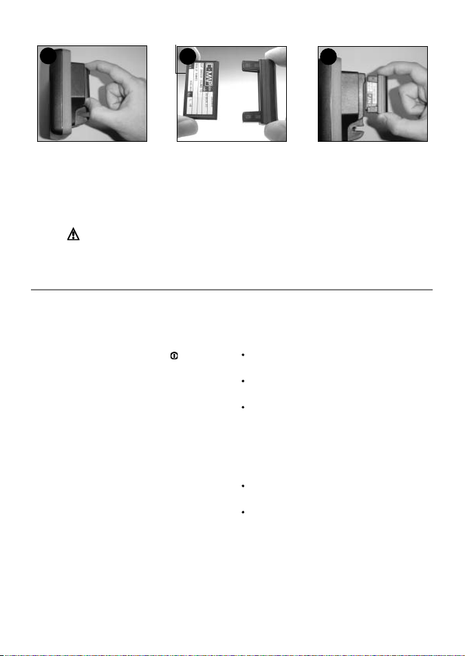
Changing the plug-in card
1
Gold contacts under here
2
2
Card
Holder
3
Turn the TRACKER off (see section 2-1).
Pull the card holder out of the TRACKER and
pull any card out of holder.
Put the card in its case.
Warning : Keep the holder in place i n the TRACKER at al l times to prevent
moisture from entering card compartment.
1-3 Removing and rep lacing the display unit
If the display unit is bracket mounted then the
display unit can easily be removed and replaced
for security or protection.
Removing the dis play unit:
1 Turn the TRACKER off by holding
display turns off.
2 Push the dust cover over the display unit.
3 Hold the display unit with one hand. Loosen
the knob on the mounting bracket and
carefully lift the unit of f the mounting
bracket.
4 The display unit has some cables plugged
into the back .
Unplug each black plug by turning the
locking collar a quar ter turn anticlockwise
and pulling the plug out.
If there is a gold plug, unscrew the locking
collar anticlockwise and pull the plug out.
5 Push the attached dust covers over the
exposed ends of the plugs to protect them.
6 Store the display unit in a safe place, such
as the TRACKER carry case or the optional
NAVMAN carry bag.
until the
Push new card into holder. Ensure the
gold contacts are on the outer edge and
underneath (see above).
Keep the card’s case.
Push card holder fully into TRACKER
Replacing the d isplay unit
1 Remove the dust covers from the plugs. Plug
the black plugs into their sockets on the back
of the display unit:
Match the colour on the end of the plug to
the colour of the nut on the socket.
Hold the plug against the socket and rotate
the plug until it slides into the socket.
Lock the plug in place by pushing the locking
collar towards the socket and turning it a
quarter turn clockwise.
Nothing will be damaged if a cable is
plugged into the wrong socket by mistake.
2 If the unit has a gold plug:
Plug it into its socket on the back of the
display unit.
Hand tighten the locking collar clockwise do not overtighten.
3 Hold the display unit in place on the
mounting bracket shaf t.
4 Adjust the tilt and rotation of the display for
best viewing and hand tighten the knob on
the mounting bracket. Remove the dust cover.
NAVMAN
TRACKER 5430/5430i Installation and Operation Manual
7
2 Basic operation
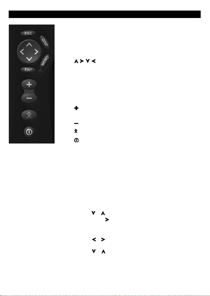
Overview of the keys
ESC Go back to an earlier menu or display. Any changes are
ignored.
DISP Show a menu of the main TRACKER displays. To go to a
display, select it from the menu (see section 2-2).
, , , Cursor keys, to move the cursor or the selection
highlight.
MENU Show a menu of the options for the current display. Press
MENU again to display the setup menu (see section 13).
ENT Start an action or accept a change or when displaying a
map press twice to create an instant waypoint at the boat
position (see section 9 -2-1).
Zoom in and display a smaller area of the chart in more
detail.
Zoom out and display a bigger area in less detail.
Man overboard (MOB, see section 2- 4).
Turn TRACKER on and off (see section 2-1); adjust the display
(see sec tion 2-3).
Keys
In this manual:
Press means to push the key for less than a second.
Hold means to hold the key down.
The internal beeper beeps when a key is pressed (to disable or
enable the beep, see section 13-1).
To select an item in a menu
The TRACKER is operated by selecting items from menus shown on
the display.
1 Press or to move the highlight to the item.
2 Press ENT or to select the item.
Change a number or word
To change a number or word on the display:
1 Press or to move the highlight to the digit or letter to
change.
Press or to change the digit or letter.
2 Repeat the above step to change any other digits or letters.
3 Press ENT to accept the change.
8
NAVMAN
TRACKER 5430/5430i Installation and Operation Manual
2-1 Turning on and off / auto power
Auto power
If the TRACKER is wired for auto power (see
section 15-3), then the TRACKER automatically
turns on and off with the boat power, and can
not be turned on or of f manually.
Turning on manually
If the TRACKER is not wired for auto power, turn
the unit on by pressing
.
Start up
After the TRACKER has been turned on:
1 The unit displays a title display for a few
seconds, then beeps again and displays a
navigation warning.
2-2 The main displays
After you have turned the TRACKER on, it shows
the satellite display until the GPS receiver gets a
GPS fix, then displays the Char t. The Chart is the
display that you will normally use for navigation.
2 If necessary, adjust the display to be easy to
read (see section 2-3).
Read the warning and press ENT.
3 The satellite display is shown.
Either wait for the GPS receiver to start up
and the status to change from ‘acquiring’
to ‘GPS fix’ (see section 7).
Or press ESC.
4 The TRACKER chart is displayed (see section 3).
Turning of f manually
If the TRACKER is not wired for auto power, turn
the unit of f by holding down until the display
turns off.
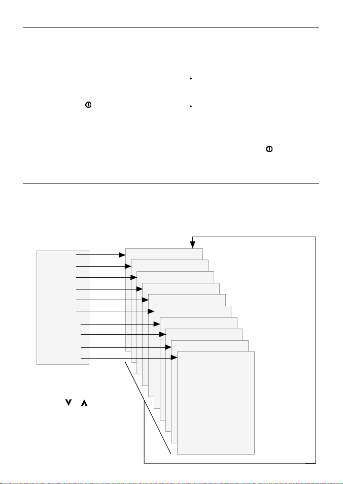
To use one of the other main displays, press DISP
for the display menu and select a display to use.
To return to the char t display, press ESC.
Display menu
Chart
Fuel
Data
Highway
Satellite
Tides
Waypoints
Routes
User card
About
Press DISP for
display menu
To select a display:
i press or to
highlight the display
ii press ENT to go to
the display
NAVMAN
TRACKER 5430/5430i Installation and Operation Manual
The main displays See:
Chart (navigation) Section 3
Fuel (fuel computer) Section 4
Data (numeric data) Section 5
Highway (boat path) Section 6
Satellite (GPS data) Section 7
Tides (tide chart) Section 8
Waypoints Section 9
Routes Section 10
User card Section 11
About Section 12
Press ESC to
return to
chart display
9

2-3 Backlight and displ ay contrast
1 Press briefly to show the display controls.
2 The display and keys are backlit, with sixteen
brightness levels.
To change the backlight, press (dimmer)
or (brighter)
2-4 Man overboard (MOB)
The MOB feature saves the boat’s position and
then navigates back to this point. To do this:
1 Press
The TRACKER beeps four times and stores the
2 The TRACKER changes to the chart display,
The chart zooms in for accurate navigation.
3 If the autopilot output is off (see section 13-8)
If the autopilot output is on, the TR ACKER
.
boat’s position as a waypoint called MOB.
with the MOB waypoint at the centre of
the chart.
If the char t can not show the required small
scale, the TRACKER changes to plotter mode
(a white display with crosshatching, and no
chart details, see section 13-2).
the TRACKER immediately star ts navigating
back to the MOB waypoint.
asks if the autopilot is active. Select:
2-5 Al arms
When the TR ACKER detec ts an alarm condition,
it displays a warning message on the display, the
internal beeper sounds and any ex ternal beepers
or lights operate.
3 To change the display contrast:
i Press to choose Contrast.
ii Press or to adjust the contrast.
4 Press ENT to accept the new values.
No: The TRACKER immediately starts navigating
back to the MOB waypoint.
Yes : The TRACKER asks if the boat is to go to the
MOB waypoint. Select:
Yes : to immediately start navigating to the
MOB waypoint.
Warn ing: This might result i n a sudden
and dangerous turn.
No: to allow time to disengage the autopilot;
then use Goto to navigate back to the MOB
waypoint (see section 3-3) .
To cancel MOB or set another MOB.
1 Press again to display a menu.
2 Select an option from the menu.
Tip: The MOB waypoint remains on the chart
after the MOB has been cancelled. To delete the
MOB waypoint, (see section 9-2-5).
Press ESC to clear the alarm. The alarm will sound
again if the alarm condition occurs again.
The TRACKER has user settable alarms plus an
alarm for loss of GPS fix (see section 13-7)
2-6 Simulate mode
Simulate mode allows a user to become familiar
with the TRACKER off the water. In Simulate
mode, the data from the GPS receiver and
other sensors is ignored and the TRACKER
generates this data internally to simulate the
movement of the boat. Otherwise, the TRACKER
functions normally.
10
To see if the TRACKER is in Simulate mode, press
DISP and selec t Satellite. If it is in Simulate
mode, then it shows Simulate at the top lef t of
the display.
To start and s top Simulate mode, (se e section 13-1).
Warning : Never have Simulate m ode on
when the TRACKE R is navigating on t he water.
NAVMAN
TRACKER 5430/5430i Installation and Operation Manual

2-7 Navi gatin g
The TRACKER has two ways of navigating, going
straight to a point or following a route.
Enter waypoints at points of interest before
starting to navigate (see section 9-2-1).
Tip: create a waypoint at the start of the trip
to navigate back to.
Goto: Going straig ht to a point
The TRACKER can navigate straight to a waypoint
or to any arbitrary point:
1 In the chart display, move the cursor to the
destination point to navigate to (see section
3-1-1).
2 Start navigating using the Goto function from
the chart menu (see section 3-3).
The chart, data and highway displays show
navigation data. The chart shows:
The boat position .
The destination point marked with a
circle.
The boat ’s plotted course to the
destination.
Two CDI lines, parallel to the boat’s
plotted course (see appendix C, CDI).
If the TRACKER is connected to an autopilot,
the TRACKER will send data to the autopilot
to steer the boat to the destination.
If the XTE alarm is enabled, an alarm will
sound if the boat deviates too much from its
intended course (to set the XTE alarm, see
section 13-7).
3 If the arrival radius alarm is enabled, then,
when the boat comes within the arrival
radius of the destination, an alarm will
sound to show that the boat has reached the
destination (to set the arrival radius alarm,
see section 13-7).
4 To stop the Goto, (see section 3-3).
Following a route
A route is a list of waypoints that the boat can
follow (see section 10).
1 To create waypoints before creating the
route, use the waypoints display (see section
9-2-1).
2 To create a route, go to the chart or routes
display (see section 10-2-1).
3 To start the route, see section (10-3-1).
The chart, data and highway displays show
navigation data. The chart shows:
The boat position .
The waypoint at the end of the current
leg marked with a circle.
The boat ’s plotted course along the leg.
Two CDI lines, parallel to the boat’s
plotted course (see appendix C, CDI).
If the TRACKER is connected to an autopilot,
the TRACKER will send data to the autopilot
to steer the boat to the destination.
If the XTE alarm is enabled, an alarm will
sound if the boat deviates too much from its
intended course (see section 13-7).
If the arrival radius alarm is enabled, then,
when the boat comes within the arrival radius
of the waypoint at the end of the current leg,
an alarm will sound (to set the arrival radius
alarm, see section 13-7).
4 The TRACKER stops navigating to the
waypoint at the end of the current leg and
start s the next leg of the route:
a When the boat comes within 0.025 nm of
the waypoint.
b Or when the boat passes the waypoint.
c Or if the waypoint is skipped (see section
10- 3-2).
5 When the boat has reached the final
waypoint, or to stop the boat following
the route at any time, cancel the route (see
section 10-3-3).
3 Chart
The chart display is the most important of the TRACKER’s displays, showing the chart, the boat ’s
position and course, and navigation data.
NAVMAN
TRACKER 5430/5430i Installation and Operation Manual
11
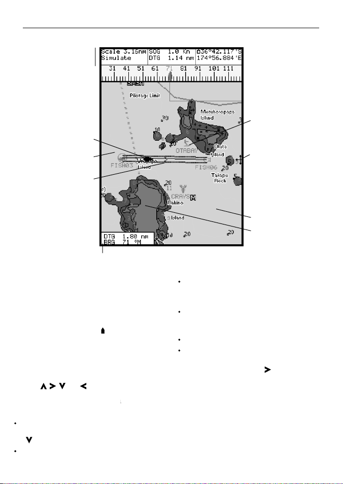
3-1 Chart display
A typic al chart display shows:
Data display. To turn
the data of f or on or to
change what data is
displayed, see sec tion
The chart. To change
the types of information
displayed, (se e sect ion
(see sec tion 3-1-1)
(see section 3-5)
Boat course and CDI
lines (see appendix
Boat is going to the
waypoint called
Distance and bearing of
cursor from boat.
3-1-8.
13-2 ).
Boat position
Boat track
C, CDI)
FISH06.
Chart is in cursor mode, press ESC to return to
centre on boat mode (see section 3-1-1)
3-1-1 Chart mode s
The Chart has two modes, centre on boat mode
and cursor mode. These are explained below.
Centre on boat mode
To switch to centre on boat mode in the chart
display, press ESC. The boat is at the centre of
the chart. As the boat moves through the water,
the chart automatically scrolls to keep the boat
in the centre of the chart. The cursor (see below)
is turned off.
Cursor mode
The keys , , and are called cursor keys.
To switch to cursor mode in the chart display,
hold down a cursor key. The cursor
moves away from the boat:
Press the key which points in the direction
that the cursor will move, for example press
to move the cursor down.
Press midway between t wo of the cursor keys
to make the cursor move diagonally.
12
appears and
Compass display
(see sec tion 3-1-4).
To turn the compass off
or on, see section 3-1-8.
Typical waypoint
(see section 9).
The cursor
(see section 3-1-1).
Sea
Land
Hold a cursor key down to make the cursor
move continuously across the display.
In Cursor mode:
The distance (+DST) and bearing (+BRG) of
the cursor from the boat are displayed at the
bottom, left corner of the display.
The chart does not scroll as the boat moves.
If the cursor reaches the edge of the display,
the chart will scroll.
For example, hold down to move the
cursor to the right side of the display and the
chart will scroll to the left.
3-1-2 Latitude and longitude
Latitude and longitude can be displayed at
the top of the chart. Normally the position is
the boat ’s position, and the latitude has a boat
symbol to show this:
NAVMAN
TRACKER 5430/5430i Installation and Operation Manual
36° 29.637' S
175° 09.165
Degrees
Minutes, to 3 decimal places
If the cursor has been moved in the last ten
seconds, then the position is the cursor’s
position, and the latitude has a cursor symbol to
show this:
(about 2 m (6 ft) resolution)
Latitude
Longitude
' E
+ 36° 29.684' S
175° 09.201
Warning : When reading t he boat positio n,
make sure the posi tion is not the cursor
position.
' E
3-1-3 Chart scale
Press to zoom in and display a smaller area of
the chart in more detail. Press to zoom out and
display a bigger area in less detail.
The chart scale can be displayed (e.g. scale
= 8 nm, see below). The scale is the vertical
distance across the currently visible char t area.
For example if the scale is 8 nm then a portion
of chart eight nautical miles high is currently
displayed.
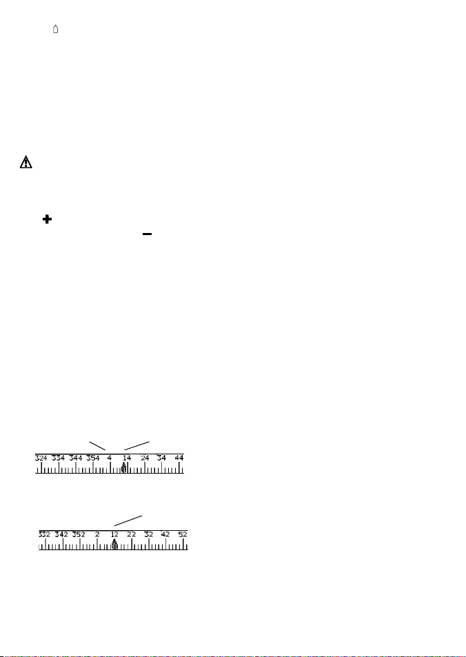
3-1-4 The compass
A compass can be displayed at the top of the
chart (see section 3-1-8).
When the boat is navigating to a point, the
compass shows the bearing to the destination
(BRG) in the middle and the boat ’s course over
ground (COG), for example here BRG is 4° and
COG is 12°:
Otherwise the compass shows the boat’s COG in
the middle, for example here COG is 12°:
BRG
COG
COG
3-1-5 Chart symbols
The chart will show symbols, such as waypoints
and chart symbols. When the cursor is placed
over a symbol for at least two seconds, a data
window appears at the bottom left of the display
with information about the symbol.
NAVMAN
TRACKER 5430/5430i Installation and Operation Manual
3-1-6 Chart information
To see stored data about a point on the chart (for
example, a chart symbol):
1 Move the cursor to that point on the chart.
2 Press MENU and selec t Chart info.
3 A menu of objects is displayed :
i Select an object to display.
ii Press ESC to return to the menu. Select
other objects.
iii Finally, press ESC to return to the chart.
3-1-7 Find nearby services
To find and display nearby services:
1 To see services near the boat’s position, press
ESC to switch to centre on boat mode. To
see services near a different point, move the
cursor to that point on the chart.
2 Press MENU and selec t Find.
3 Select the type of service. There are three
types of service:
Ports
A list of ports is displayed. Select the port
to display.
To search for a por t:
i Press MENU and selec t Find.
ii Enter some or all of the letters of the
port name. Press ENT.
Port ser vices
i Select the type of service to find.
ii A list of places with this service are
displayed. Select the place to display.
Tide stations
A list of tide stations is displayed. Selec t
the station to display. The chart redraws
with the tide station centred. To now
display a tide chart (see section 8) for the
station:
i Press MENU and selec t Chart info.
ii Select Tide height.
3-1-8 Change the data display and compass
display
Numeric data and a compass can be displayed at
the top of the chart display. To change these:
1 Press MENU and selec t Data header.
2 To turn the data display off or on:
i Select Data.
ii Select Off or On.
13

3 To choose the size of the numbers:
i Select Size.
ii Select:
Small: displays three fields per line and
up to four lines.
Medium/Large: displays two fields per
line and up to four lines.
4 To change the data display:
i Select Data setup.
ii Change a data field:
a Press the cursor keys to highlight
the field.
3-2 Distance and bearing calculator
The distance and bearing calculator can plot a
course of one or several legs and to show the
bearing and length of each leg, as well as the
total distance along the course. The completed
course can be converted into a route.
To use the distance and bearing calculator:
1 Press ESC until the char t display is displayed.
Press MENU and select Distance.
2 Move the cursor to the start of the first leg. It
does not matter if this point is a waypoint or
not. Press ENT.
3 To add a leg to the course, move the cursor
to the end of the leg. It does not matter if this
point is a waypoint or not. The display shows
3-3 Goto
Goto is a simple way of navigating straight to
one point.
To start the Goto
1 Choose the point to go to:
To go to a waypoint or to any point on the
chart:
i Press ESC until the char t display is
displayed.
ii Move the cursor to the destination.
iii Press MENU and select Goto.
To go to a waypoint from the waypoints
display:
i Press DISP and selec t Waypoint s.
ii Press or to highlight the
destination waypoint.
14
b Press ENT to display a menu of the
data that can be shown in the field.
c Select the data to show in the field;
select None to leave the field empty.
iii Repeat the above step to set the other
data fields. Press ESC.
Tip: If less than four lines are used,
the numeric data will take up less of the
chart area.
5 To turn the compass display off or on:
i Select Compass.
ii Select Off or On.
6 Finally, press ESC to return to the chart
display.
the bearing and length of the leg, as well
as the total distance along the course.
Press ENT.
4 To remove the last leg from the course, press
MENU and selec t Remove.
5 Repeat the above two steps to enter the
whole course.
6 To save the new course as a route, press
MENU and selec t Save. This also saves any
new points on the course as new waypoints,
with default names. If necessary, edit the
route later (see section 10-2-2) and edit any
new waypoints later (see section 9-2-3).
7 Finally, press ESC to return to the chart
display.
iii Press MENU and select Goto.
Warning : Make sure the course does not
pass over land or dang erous waters.
2 The TRACKER starts navigating to the
destination (see section 2-7). The chart
shows:
The destination point marked with a
circle.
The boat ’s plotted course to the
destination.
Two CDI lines, parallel to the boat’s
plotted course (see appendix C, CDI).
To cancel a Goto
1 Press ESC until the char t display is displayed.
2 Press MENU and selec t Cancel goto.
NAVMAN
TRACKER 5430/5430i Installation and Operation Manual
 Loading...