


G - P I L O T 3 1 0 0
A U T O P I L O T
Installation Manual
English.............. |
3 |
Español........... |
32 |
Português....... |
61 |
w w w . n a v m a n . c o m

NAVMAN
.

Contents |
|
Important................................................................................................ |
4 |
1 Introduction......................................................................................... |
5 |
1-1 A typical installation .................................................................................... |
5 |
1-2 Using the G-PILOT 3100 with other instruments.......................... |
6 |
1-2-1 Using other instruments .......................................................................... |
6 |
1-2-2 NavBus ................................................................................................... |
6 |
1-2-3 NMEA...................................................................................................... |
6 |
2 G-PILOT 3100 hardware..................................................................... |
7 |
2-1 What comes with your G-PILOT 3100 ....................................................... |
7 |
2-2 Other parts required ................................................................................... |
8 |
3 Installation........................................................................................... |
8 |
3-1 Installation sequence ................................................................................. |
8 |
3-2 Installation guide ........................................................................................ |
9 |
3-2-1 Location guide..................................................................................... |
9 |
3-2-2 Wiring guide ........................................................................................ |
9 |
3-3 Installing the main unit ............................................................................. |
10 |
3-4 Installing the power supplies and steering drive ...................................... |
11 |
3-4-1 Installing the power supplies ............................................................. |
11 |
3-4-2 Installing the steering drive ............................................................... |
12 |
3-5 Installing the rudder feedback unit ........................................................... |
16 |
3-6 Installing the compass.............................................................................. |
19 |
3-7 Installing the gyro ..................................................................................... |
21 |
3-8 Installing the display unit and other instruments ...................................... |
23 |
4 Dockside setup................................................................................. |
25 |
4-1 Start dockside setup................................................................................. |
25 |
4-2 Calibrating the rudder feedback unit ........................................................ |
26 |
5 Sea trials ........................................................................................... |
27 |
5-1 Calibrating the compass........................................................................... |
27 |
6 Aligning the compass and the rudder ............................................ |
28 |
6-1 Aligning the compass ............................................................................... |
28 |
6-2 Aligning the rudder ................................................................................... |
28 |
Appendix A - Specifications ............................................................... |
29 |
Appendix B - Alarm and warning messages..................................... |
29 |
Appendix C - Troubleshooting ........................................................... |
31 |
Appendix D - How to contact us ........................................................ |
90 |
G-PILOT 3100 Installation Manual |
NAVMAN |
3 |

Important
It is the owner’s sole responsibility to install and use the instrument and transducer/s in a manner that will not cause accidents, personal injury or property damage. The user of this product is solely responsible for observing safe boating practices.
The choice, location, and installation of all components in any autopilot system is critical. If installation is not correct, the unit can not perform at its designed potential. If in doubt, consult your Navman dealer. Ensure that any holes that cut are in a safe position and will not weaken the boat's structure. If in doubt, consult a qualified boat builder.
Using the G-PILOT 3100:
The G-PILOT 3100 is intended as an aid to save a helmsman from having to steer for long periods of time, not as the main means of steering the boat.
The G-PILOT 3100 is not intended for use in extreme weather, in adverse conditions or in water near other boats, dangerous waters or land.
The G-PILOT 3100 can not control the boat better than a helmsman. In adverse conditions steer the boat manually.
Never leave the helm unattended. Keep a watch at all times. The helmsman should always monitor the course of the boat and the G-PILOT 3100 and be ready to resume steering the boat manually.
The performance of the G-PILOT 3100 can be affected by the failure of a part, environmental conditions, improper installation and use.
NAVMAN NZ LIMITED DISCLAIMS ALL LIABILITY FOR ANY USE OF THIS PRODUCT IN A WAY THAT MAY CAUSE ACCIDENTS, DAMAGE OR THAT MAY VIOLATE THE LAW.
As Navman is continuously improving this product we retain the right to make changes to the product at any time which may not be reflected in this version of manual. Please contact your nearest Navman office if you require any further assistance.
Governing Language: This statement, any instruction manuals, user guides and other information relating to the product (Documentation) may be translated to, or has been translated from, another language (Translation). In the event of any conflict between any Translation of the Documentation, the English language version of the Documentation will be the official version of the Documentation.
Copyright © 2003 Navman NZ Limited, New Zealand. All rights reserved. Navman is a registered trademark of Navman NZ Limited.
FCC Statement
Note: This equipment has been tested and found to comply with the limits for a Class B digital device, pursuant to Part 15 of the FCC Rules. These limits are designed to provide reasonable protection against harmful interference in a normal installation. This equipment generates, uses and can radiate radio frequency energy and, if not installed and used in accordance with the instructions, may cause harmful interference to radio communications. However, there is no guarantee that interference will not occur in a particular installation. If this equipment does cause harmful interference to radio or television reception, which can be determined by turning the equipment off and on, the user is encouraged to try to correct the interference by one or more of the following measures:
Reorient or relocate the receiving antenna.
Increase the separation between the equipment and receiver.
Connect the equipment into an output on a circuit different from that to which the receiver is connected.
Consult the dealer or an experienced technician for help.
A shielded cable must be used when connecting a peripheral to the serial ports.
4 |
NAVMAN |
G-PILOT 3100 Installation Manual |
1 Introduction
Using this manual
This manual describes how to install and set up the G-PILOT 3100. Refer to the separate
G-PILOT 3100 Operation Manual for information on how to use the G-PILOT 3100.
To install a G-PILOT 3100, you must perform installation, dockside setup and sea trials (see sections 3, 4 and 5).
To fully set up a G-PILOT 3100 after a part has been changed or if a problem is suspected, perform dockside setup and sea trials (see sections 4 and 5).
To verify that the G-PILOT 3100 is operating correctly, perform sea trials (see section 5).
Cleaning and maintenance
Clean the parts of the G-PILOT 3100 with a damp cloth or mild detergent. Avoid abrasive cleaners, petrol or other solvents.
Do not paint any part of the G-PILOT 3100 except for the cables.
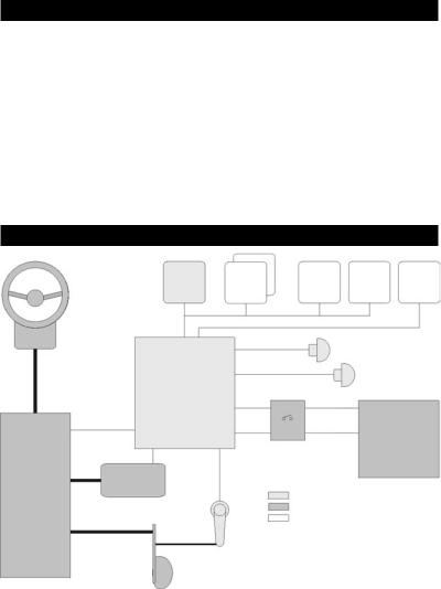
1-1 A typical installation
Optional instruments
Manual helm
Clutch drive (optional)
Rudder control |
Steering |
drive |
Rudder
Display |
More |
WIND |
SPEED |
GPS |
unit |
display |
3100 |
3100 |
NMEA |
|
units |
|
|
|
NavBus |
|
NMEA |
|
|
|
|
|
|
|
|
|
Compass |
|
|
Main |
|
|
Gyro |
|
|
|
|
|
|
unit |
|
|
Light duty |
|
|
|
|
||
|
|
|
Heavy duty |
|
|
Power switch or switches |
|
||
|
and power protection |
12 V DC |
||
|
|
|
Power supply |
|
Key
Parts supplied with G-PILOT
Other parts required
Optional parts
|
Note: Above shows typical |
|
Rudder |
installation only. Please refer |
|
to the information supplied with |
||
feedback unit |
||
your drive for further information. |
||
|
G-PILOT 3100 Installation Manual |
NAVMAN |
5 |

1-2 Using the G-PILOT 3100 with other instruments
1-2-1 Using other instruments
The G-PILOT 3100 can use data from these instruments:
GPS: A GPS or chartplotter, such as a Navman TRACKER 5000 series chartplotter must be connected to the G-PILOT 3100 for the G-PILOT 3100 to operate in GPS mode (see the G-PILOT 3100 Operation Manual). Note: GPS must be via NMEA input.
WIND:Awind instrument, such as a Navman WIND 3100 series, must be connected to the G-PILOT 3100 for the G-PILOT 3100 to operate in WIND mode (see the G-PILOT 3100 Operation Manual).
SPEED: A speed instrument, such as:  Navman’s SPEED 3100 with a
paddlewheel speed sensor
or a GPS or chartplotter, such as Navman’s TRACKER 5000 series chartplotter can be connected to the G-PILOT 3100 to increase steering accuracy.
Note: The speed from a paddlewheel sensor is the speed that the boat is moving through the water. The speed from a GPS is the speed over the ground. If there is a water current then these two speeds will be different. If the G-PILOT 3100 is connected to an instrument with a paddlewheel sensor and to a GPS, then the G-PILOT 3100 will automatically use the speed from the paddlewheel sensor instrument.
1-2-2 NavBus
NavBus is a Navman proprietary system that allows systems of multiple instruments to be built using a single set of transducers. When instruments are connected by NavBus:
If you change the units, alarms or calibration in one instrument, then the values will automatically change in all other instruments of the same type.
Each instrument can be assigned to a group of instruments, called a backlight group (see BKL GROUP in the FACTORY menu, in the G-PILOT 3100 Operation Manual). If you change the backlight in an instrument in group 1, 2, 3 or 4 then the backlight will automatically change in the other instruments in the same group. If
you change the backlight in an instrument in group 0 then no other instruments are affected.
If an alarm sounds, mute it on any instrument which can display that alarm.
For more information, refer to the NavBus Installation and Operation Manual. Note: GPS must be via NMEA input.
NavBus and the G-PILOT 3100
The G-PILOT 3100 will automatically work with additional display units.
The G-PILOT 3100 can receive wind data from Navman’s WIND 3100 over NavBus.
The G-PILOT 3100 can receive speed data from Navman’s SPEED 3100 over NavBus.
1-2-3 NMEA
NMEA is an industry standard, but is not as flexible as NavBus as it requires dedicated connections between instruments. The G- PILOT has one NMEA input port and one port that can be configured to be an input or an output (See G-PILOT 3100 Operation Manual).
G-PILOT 3100 NMEA inputs
GPS: The G-PILOT 3100 can receive NMEA GPS data from a compatible GPS or chartplotter, such as Navman’s TRACKER 5000 series chartplotter:
XTE (from APA, APB or XTE sentences) is required for the G-PILOT to use GPS mode
BRG (from APA sentences) and BOD (from APA or APB sentences) are optional and improve performance
COG (from VTG sentences) is optional and can be displayed.
WIND: The G-PILOT 3100 can receive NMEA wind data from a compatible wind instrument:
True or apparent wind direction (from MWV sentences) is required for the G-PILOT to use Wind mode.
SPEED: The G-PILOT 3100 can receive NMEA speed data from a compatible paddlewheel or GPS instrument:
SOG (from VTG sentences) is optional and improves performance.
Note: If the G-PILOT 3100 is connected to a
6 |
NAVMAN |
G-PILOT 3100 Installation Manual |
Navman 3100 series wind or speed instrument using NavBus, then the G-PILOT 3100 will automatically receive and use the wind or speed data, and the NMEA connection need not be wired.
G-PILOT 3100 NMEA outputs
The NMEA 2 port can be configured to be an input or to be output:
either heading (HDG & HDT) and rudder angle (RSA) once per second
 or heading (HDG) ten times per second (see NMEA 2 DAT in the FACTORY menu, See G-PILOT 3100 Operation Manual).
2 G-PILOT 3100 hardware
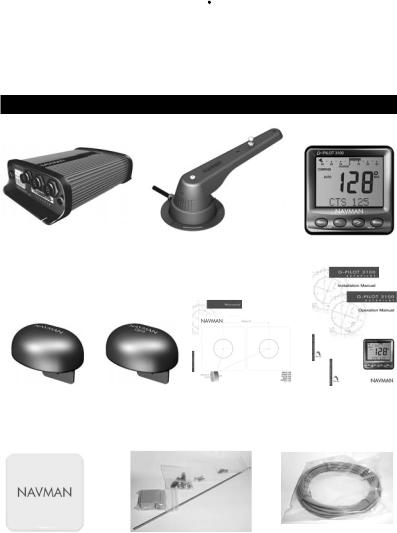
2-1 What comes with your G-PILOT 3100
Main unit |
Rudder feedback unit |
Display unit |
|
|||||
|
|
|
|
|
|
|
|
|
|
|
|
|
|
|
|
|
|
|
|
|
|
|
|
|
|
|
|
|
|
|
|
|
|
|
|
|
|
|
|
|
|
|
|
|
|
|
|
|
|
|
|
|
|
|
|
|
|
|
|
|
|
|
|
|
|
|
|
|
|
|
|
Compass, with 10 |
Gyro, with 10 m |
Warranty and dis- |
This Installation |
m (33 ft) attached |
(33 ft) attached |
play unit mounting |
manual, |
cable |
cable |
template |
Operation manual. |
Protective cover for |
Mounting hardware, cable cover, |
2 mm (#14) twin stranded |
display unit |
strain relief, spare fuses |
cable for high current wiring |
G-PILOT 3100 Installation Manual |
NAVMAN |
7 |

2-2 Other parts required
Power supply: The G-PILOT 3100 requires two power supplies, both nominally 12 V DC:
A heavy duty supply for the steering drive
A light duty supply for the G-PILOT 3100 electronics and display unit; this supply also powers any additional display units and other instruments.
The power supplies require one or two switches and fuses or circuit breakers (see section 3-4).
Steering drive: The G-PILOT 3100 can power a hydraulic pump, constantly running pump set, hydraulic linear drive or mechanical drive rated at 12 V DC and up to 20 A.
Rudder linkage: To link rudder to rudder feedback unit (see section 3-5).
For wiring, see Select Wire Table in section 3-4-2.
External beepers or lights (optional ): The external output is switched to ground, 30 V DC and 250 mA maximum. If the beepers and lights require more than 250 mA total, fit a relay.
Other marine instruments (optional): Wind, speed or GPS instruments can be connected (see section 1-2).
Other parts: For systems of several instruments, wiring and connectors are required. Navman junction boxes can simplify wiring several Navman instruments together (see section 1-2 or the NavBus Installation and Operation Manual).
Coupling connectors and 10 m (33 ft) extension cables are available to extend the rudder feedback unit, compass or gyro cables. Do not fit more than one extension cable to each unit.
3 Installation
Warning Correct installation is critical to the performance of the unit. It is vital to read this manual and the documentation that comes with the other parts before starting installation.
Warning
The G-PILOT main unit is not waterproof. Mount the unit in a dry place.
The G-PILOT display unit is waterproof from the front. Protect the rear of the unit
from water, or else water might enter the breathing hole and damage the unit. The warranty does not cover damage caused by moisture or water entering the back of the unit.
The compass, gyro and rudder feedback unit are completely waterproof.
Warning Ensure that any holes that you cut will not weaken the boat’s structure. If in doubt, consult a qualified boat builder.
3-1 Installation sequence
The recommended installation sequence is:
1Read this manual and the documentation that comes with the other parts.
2Plan the installation: select where the equipment and wiring will be installed (see section 3-2).
3Install the main unit (see section 3-3).
4Install the steering drive and wire the heavy duty and light duty power supplies (see section 3-4).
5Install the rudder feedback unit (see section 3-5).
6Install the compass (see section 3-6).
7Install the gyro (see section 3-7).
8Install the display unit and any other marine instruments that will be used with the G-PILOT 3100 (see section 3-8).
9Carry out the dockside setup (see section 4).
10Carry out the sea trials (see section 5).
If you are unsure where a part should be installed, mount and wire the part temporarily, without cutting holes in the boat. After the sea trials have been completed, install and wire the part permanently.
8 |
NAVMAN |
G-PILOT 3100 Installation Manual |

3-2 Installation guide
This is a general guide for locating and wiring the parts of the G-PILOT 3100. The instructions for a particular part may have additional requirements.
3-2-1 Location guide
Do not mount any part where it can be used as a handhold, where it will interfere with the operation of the boat or where it might be submerged.
Do not mount any part where it will interfere with launching or retrieving the boat.
Do not mount any part within 0.5 m (20") of the plane of a radar antenna.
Mount the compass and gyro:
At least 1 m (3 ft) away from sources of electrical signals or noise, such as the batteries, high-current cables, other boat cables, engines, fluorescent lights, power inverters, radio or radar transmitters and antennas.
At least 1 m (3 ft) away from equipment containing a magnet, such as a compass.
3-2-2 Wiring guide
The G-PILOT 3100 has two kinds of cables:
The heavy-duty power supply and steering drive usually require high-current cables:
Select the wire gauge from the wire size table (see section 3-4-2).
Fit high-current cables at least 1 m (3 ft) away from other electronic devices in the boat.
Keep the cables as short as possible.
Twin 2 mm (#14) cable is supplied with the G-PILOT 3100 and can be used for the high current cable if its gauge is suitable.
All the other cables are low-current:
Fit low-current cables at least 1 m (3 ft) away from sources of electrical signals or noise, such as the high-current cables, other boat cables, engines, fluorescent lights, power inverters and radio or radar transmitters and antennas.
If the cable for the rudder feedback unit, compass or gyro is too long, do not shorten the cable; instead coil the cable up near the main control unit.
The cable for the rudder feedback unit, compass or gyro can be extended by adding a 10 m (33 ft) extension cable and coupling connector. Do not fit more than one extension cable to each unit.
When fitting any type of cable:
Do not crush, pinch or strain the cable.
Secure the cable at regular intervals. Ensure no connectors or exposed terminals are in the bilge.
G-PILOT 3100 Installation Manual |
NAVMAN |
9 |
3-3 Installing the main unit
Physical
|
|
.87") |
200 |
mm |
(7 |
|
||
|
|
55 mm (2.16")
Screws |
|
|
||
140 |
|
90 |
|
|
mm |
mm |
|
||
|
(3 |
|||
|
(5 |
|
. |
|
|
|
54") |
||
|
|
. |
|
|
|
|
10") |
apart |
|
|
|
|
|
.36") |
|
|
|
|
(2 |
|
|
|
|
mm |
|
|
|
60 |
|
IMPORTANT: 60 mm (2.36") clearance required for cables
Installation
Find a suitable location for the unit:
|
|
.87") |
200 |
mm |
(7 |
|
IMPORTANT: 200 mm (7.87") clearance required for cover removal
|
|
.24") |
apart |
|
|
|
|
|
|
(7 |
|
|
184 |
mm |
|
holes |
|
|
|
|
|
|
|
Screw |
|
|
|
In a dry, cool place; if possible not the engine room.
Close to the high-current power supply and the steering drive, to reduce the length of the high current wiring.
Accessible for installation and service.
If possible on a vertical panel which does not vibrate.
Follow the location guide (see section 3-2-1).
Mount the unit with the cable connectors at the bottom or to one side, using the screws provided. Do not mount the unit with the connectors at the top, because dust or moisture might enter the unit.
10 |
NAVMAN |
G-PILOT 3100 Installation Manual |
3-4 Installing the power supplies and steering drive
3-4-1 Installing the power supplies
The G-PILOT 3100 requires a light and a heavy duty power supply, both 12 V DC (10.5 to 16.5 V DC).
Note:
Keep all wiring as short as possible. |
|
Main unit |
For the heavy duty supply, use the wire size |
|
|
|
|
|
given in the table (see section 3-4-2). |
|
|
Follow the wiring guide (see section 3-2-2). |
|
|
Power supply: one switch configuration |
|
|
Choose this configuration to have one switch to turn the |
|
|
G-PILOT 3100 and any other instruments on and off. |
|
|
|
|
1 2 3 4 5 6 7 8 |
Fit strain relief |
|
Connector |
|
|
|
12 V DC power |
Heavy |
cover |
supply, current to |
duty |
|
suit drive |
|
Light duty |
Fuse 1 A |
|
|
|
power |
|
Circuit breaker or fuse |
|
|
and switch, current rating |
|
|
to suit steering drive |
|
|
Power supply: two switch configuration
Choose this configuration to be able to turn the drive power off and leave other instruments powered.
Fit strain relief
12 V DC power supply, current to suit drive
Fuse 1 A |
Switch |
Circuit breaker or fuse and switch, current rating to suit steering drive
1 2 3 4 5 6 7 8
Connector Heavy cover duty power
Light duty power
Note: If powering more than three extra display units or other 3100 series instruments, fit another switch and fuse for the light duty power supply for these extra instruments
G-PILOT 3100 Installation Manual |
NAVMAN |
11 |
 Loading...